manuals.online logo
Brands
  1. Home
  2. •
  3. Brands
  4. •
  5. Toa
  6. •
  7. Music Mixer
  8. •
  9. Toa RX-7-248 Instruction Manual

Toa RX-7-248 Instruction Manual

This manual suits for next models

2

Other Toa Music Mixer manuals

Toa M-1212E User manual

Toa

Toa M-1212E User manual

Toa D-901 User manual

Toa

Toa D-901 User manual

Toa M-243 User manual

Toa

Toa M-243 User manual

Toa CX-124 User manual

Toa

Toa CX-124 User manual

Toa RX-212 Instruction Manual

Toa

Toa RX-212 Instruction Manual

Toa D-2000 Series User manual

Toa

Toa D-2000 Series User manual

Toa Q-2008SPD User manual

Toa

Toa Q-2008SPD User manual

Toa MX-401 Instruction Manual

Toa

Toa MX-401 Instruction Manual

Toa CX-124 User manual

Toa

Toa CX-124 User manual

Toa D-2012C User manual

Toa

Toa D-2012C User manual

Toa M-243 User manual

Toa

Toa M-243 User manual

Toa M-164E User manual

Toa

Toa M-164E User manual

Toa RX-31C Instruction Manual

Toa

Toa RX-31C Instruction Manual

Toa MX-104 Instruction Manual

Toa

Toa MX-104 Instruction Manual

Toa RX-208 Instruction Manual

Toa

Toa RX-208 Instruction Manual

Toa D-901 User manual

Toa

Toa D-901 User manual

Toa M-1212E User manual

Toa

Toa M-1212E User manual

Toa D-2012AS Programming manual

Toa

Toa D-2012AS Programming manual

Toa M-243 User manual

Toa

Toa M-243 User manual

Toa MX-628 User manual

Toa

Toa MX-628 User manual

Toa MX-601 Instruction Manual

Toa

Toa MX-601 Instruction Manual

Toa D-901 User manual

Toa

Toa D-901 User manual

Toa M-9000 User manual

Toa

Toa M-9000 User manual

Toa RX-31C Instruction Manual

Toa

Toa RX-31C Instruction Manual

Popular Music Mixer manuals by other brands

Neve 8816 user manual

Neve

Neve 8816 user manual

Mackie Onyx Analogue Mixer brochure

Mackie

Mackie Onyx Analogue Mixer brochure

Behringer EUROPOWER PMP518M user manual

Behringer

Behringer EUROPOWER PMP518M user manual

Peavey S-32 Sanctuary Series Operation guide

Peavey

Peavey S-32 Sanctuary Series Operation guide

Rane MP 4 Operator's manual

Rane

Rane MP 4 Operator's manual

True T9 Touchscreen Console owner's manual

True

True T9 Touchscreen Console owner's manual

Studiomaster Air Pro 24 instruction manual

Studiomaster

Studiomaster Air Pro 24 instruction manual

Pioneer SVM 1000 - Audio/Video Mixer Service manual

Pioneer

Pioneer SVM 1000 - Audio/Video Mixer Service manual

Roland M-160 owner's manual

Roland

Roland M-160 owner's manual

Yamaha MR1642 Operation manual

Yamaha

Yamaha MR1642 Operation manual

Ecler MAC40v user manual

Ecler

Ecler MAC40v user manual

Pioneer DJM 909 - Battle Mixer W/Effects operating instructions

Pioneer

Pioneer DJM 909 - Battle Mixer W/Effects operating instructions

Veeder-Root TLS-350 Series System setup manual

Veeder-Root

Veeder-Root TLS-350 Series System setup manual

Alto APM80.QUAD user manual

Alto

Alto APM80.QUAD user manual

Omnitronic PM-211 user manual

Omnitronic

Omnitronic PM-211 user manual

SoundCraft B400 user guide

SoundCraft

SoundCraft B400 user guide

Roland SoundCanvas SC-8820 owner's manual

Roland

Roland SoundCanvas SC-8820 owner's manual

CARVIN RX 1200 operating manual

CARVIN

CARVIN RX 1200 operating manual

manuals.online logo
manuals.online logoBrands
  • About & Mission
  • Contact us
  • Privacy Policy
  • Terms and Conditions

Copyright 2025 Manuals.Online. All Rights Reserved.

TOA MIXING CONSOLE
Operating Instruction Manual
Model RX-7-164, RX-7-248, RX-7-328
TOA ELECTRIC CO., LTD.
KOBE, JAPAN
Precautions .................................................. 2
eneral Description ............................................ 3
Features ....................................................... 4
Specifications
&
Characteristics
...............................
6
Input
&
Output
Specifications
................................
7
Level
Diagrams
&
Characteristics
Diagrams
....................
8
IPM-7
(Input
Module)
.......................................
9
FM-7 ( roup/Foldback Module).......................... 11
EM-7
( roup/Echo
Module)
................................
12
P M-7
(Program
Module)
...................................
13
PHM-7 (Phones Module)....................................... 14
TBM-7
(Talkback
Module)
...................................
15
PSM-7 (Power Supply M odule)................................ 16
Meter
Panel
(RXM-7-25,
RXM-7-35,
RXM-7-43)
................
17
RPS-7
(Power
Supply
Unit)
..................................
21
eneral
Information
on
using
the
mixing
console
...............
22
Function
Details
............................................
24
Connection
Examples
I
......................................
31
Connection Examples
II ..................................... 32
Module
Replacement
........................................
33
Dimensional Diagrams (RX-7-164, RX-7-248, RX-7-328,
RXM-7-25, RXM-7-35, RXM-7-43, RPS-7).................... 35
Block Diagram............................................... 42
Contents
— 1 —
Precautions
1. Power Supply Unit RPS-7)
The RPS-7 is separate from the console.
If the power switch on the RPS-7 is turned "on" without a connection between the
RPS-7 and the board using the accessory cable packed in the RPS-7, power is not
supplied to the board. The power switch must be "on" after the connection is made.
2. Power Supply
The RPS-7 is designed to operate on local AC (50/60Hz) mains, ±10%.
3. Fuse Replacement
The front panel of the RPS-7 is provided with a fuse holder for the AC line. Replace
only with the Identical Type and Value Fuse.
4. XLR Cannon) Connector
The connectors are wired in such a manner that pin 1 is ground (shield), pin 2 is cold
(low, minus), and pin 3 is hot (high, plus).
5. Phantom Power Supply
Each RX-7 incorporates a 48V DC Phantom Power circuit. If phantom power is
required, the phantom power Master Switch on the rear panel of the Power Supply
Module should be "on", and the phantom power switch on the front panel of each
Input Module for which phantom power is required should be "on". When using
phantom power, avoid connecting unbalanced microphones or connecting other
equipment for which the output transformer center tap is grounded.
6. Description of components and functions
Various descriptions are used by different manufacturers, depending on each
manufacturer's standards. In our Operating and Instruction Manual, explanation of
components and functions is made according to our usage for terminology.
— 2 —
General Description
TOA's RX-7 is a modular 16, 24 or 32 input channel, 4 group output, 4 to 8 program
output mixing console. It is designed to meet a wide variety of requirements in
professional sound reinforcement and recording applications. It is well designed to
withstand the rigors of "on the road" use. Modular construction assures versatility in
functions, reliability and serviceability.
There are three "standard" models of RX-7 consoles. The RX-7-164 has 16 input
channels, 4 group outputs and 4 program outputs, and consists of the frame/case,
power supply unit, and modules, as follows.
16 IPM-7 (Input Module)
2 FM-7 ( roup/Foldback Module)
2 EM-7 ( roup/Echo Module)
2 P M-7 (Program Module)
1 PHM-7 (Phones Module)
1 TBM-7 (Talkback Module)
1 PSM-7 (Power Supply Module)
1 RXM-7-25 (RX-7-164 Frame/Case)
1 RPS-7 (Power Supply Unit)
The RX-7-248 has 24 input channels, 4 group outputs and 8 program outputs, and
consists of the following modules, frame/case, and power supply unit.
24 IPM-7 (Input Module)
2 FM-7 ( roup/Foldback Module)
2 EM-7 ( roup/Echo Module)
4 P M-7 (Program Module)
1 PHM-7 (Phones Module)
1 TBM-7 (Talkback Module)
1 PSM-7 (Power Supply Module)
1 RXM-7-35 (RX-7-248 Frame/Case)
1 RPS-7 (Power Supply Unit)
The RX-7-328 has 32 input channels, 4 group outputs and 8 program outputs, and
consists of the following modules, frame/case and power supply unit.
32 IPM-7 (Input Module)
2 FM-7 ( roup/Foldback Module)
2 EM-7 ( roup/Echo Module)
4 P M-7 (Program Module)
1 PHM-7 (Phones Module)
1 TBM-7 (Talkback Module)
1 PSM-7 (Power Supply Module)
1 RXM-7-43 (RX-7-348 Frame/Case)
1 RPS-7 (Power Supply Unit)
All modules are usable for all RX-7 series consoles.
— 3 —
GROUP/FOLDBACK and GROUP/ECHO MODULES
1. AUX INPUT ( roup/Foldback Module) and ECHO IN ( roup/Echo Module) are
both balanced (transformer-isolated), with Low, Mid and High-EQ provided for
both types of inputs.
2. ACCESSORY SEND/RECEIVE jacks are located on the rear of the modules for
inserting signal processing devices.
3. roup On/Off pushbutton allows rapid punch-ins and punch-outs for temporary
killing of an output without disturbing the mixed level.
4. Foldback (FB) MASTER and ECHO SEND controls adjust each output's level
individually.
5. Peak indicators turn on the warn the operator when the signal level reaches l0dB
above nominal.
INPUT MODULE
1. Phantom Power ON/OFF switch.
2. TRIM gain control offers extremely convenient operation when used in
conjunction with INPUT LEVEL switch.
3. MID-EQ is peaking equalization, and its center frequency can be set by a
continuously variable frequency control knob.
4. Two foldback control knobs for the 2 foldback busses. One is Pre-fader and the
other is associated with the PRE-POST selector switch for additional effects.
5. Two echo control knobs for the 2 echo busses. One is Post-fader and the other is
associated with the PRE-POST selector switch.
6. Channel ON/OFF pushbutton provides quick connection or disconnection of the
incoming signal to the mixing busses. The associated green LED illuminates when
the channel is connected to the mixing busses.
7. DIRECT OUT delivers a signal taken directly from the input module, bypassing
the pan pot and group assignment switches. This output is provided for direct
routing to a tape recorder track.
8. ACCESSORY SEND/RECEIVE jacks permit inserting a signal processing device
into the signal path, or can be used to re-route the signal in special applications.
9. PEAK indicator LED turns on when the input signal reaches l0dB above nominal,
to warn the operator to adjust the input sensitivity.
Features
— 4 —
PROGRAM MODULE
1. roup 1, 2, 3 and 4 controls pick up the signal from the four group out busses and
assign them to the program output. The program output is therefore suitable for
feeding the signal to the house sound system.
2. Program On/Off pushbutton determines whether the individual program output
signal is to be fed to the rest of the sound system or other equipment.
3. Peak indicator for detecting overload condition.
4. Program channel mixed signal can be monitored through headphones by phones
selector switches (L and/or R) prior to feeding the signal to the rest of the sound
system or other equipment.
PHONES MODULE
1. Foldback 1 or 2, Echo 1 or 2, Program L and R, Air Monitor L and R can be
monitored through headphones by a cluster of selection switches.
2. Air Monitor L and R inputs are provided with PHANTOM power ON/OFF switch.
3. L and R monitor output jacks are located on the rear for monitor loudspeakers
(power amplifiers).
TALKBACK MODULE
1. Oscillator/Pink noise enerator includes 400Hz, 1kHz and 10kHz sine wave
signals and pink noise for signal tracing, tape machine alignment, sound system
setup or trouble shooting purposes.
2. These signals can be fed to all mixing busses except the cue buss.
— 5 —
Specifications & Characteristics
GENERAL SPECIFICATIONS RX-7-164, RX-7-248 AND RX-7-328
Frequency Response (Measurement of source impedance 150
ohms)
+0dB, -0.5dB; 50Hz to 20kHz +0dB, -2.0dB; 20Hz to 30 kHz
Total Harmonic Distortion
Less than 0.5% at +4dB* output at 1kHz
Hum and Noise (20Hz to 20kHz, input termination of 150 ohms,
Input Level Switches at -60dB, Input Trim at 0)
-128dB* Equivalent Input Noise
-130dB* Equivalent Input Noise, IHF A weighted
-64dB* (68dB S/N) roup Out, roup and one Input Fader
at nominal level
-64dB* (68dB S/N) Program Out, P M Master and roup
controls at max. level, all roup Faders and one Input Fader
at nominal level
-64dB* (68dB S/N) FB Out or Echo Send, FB Master or Echo
Send control and one FB or Echo mix control at nominal
level
Maximum Voltage Gain
84dB CH IN to roup Out
84dB CH IN to Program Out
84dB CH IN to FB Out
94dB CH IN to Echo send
20dB AUX IN to roup Out
20dB ECHO IN to roup Out
10dB SUB IN to roup Out
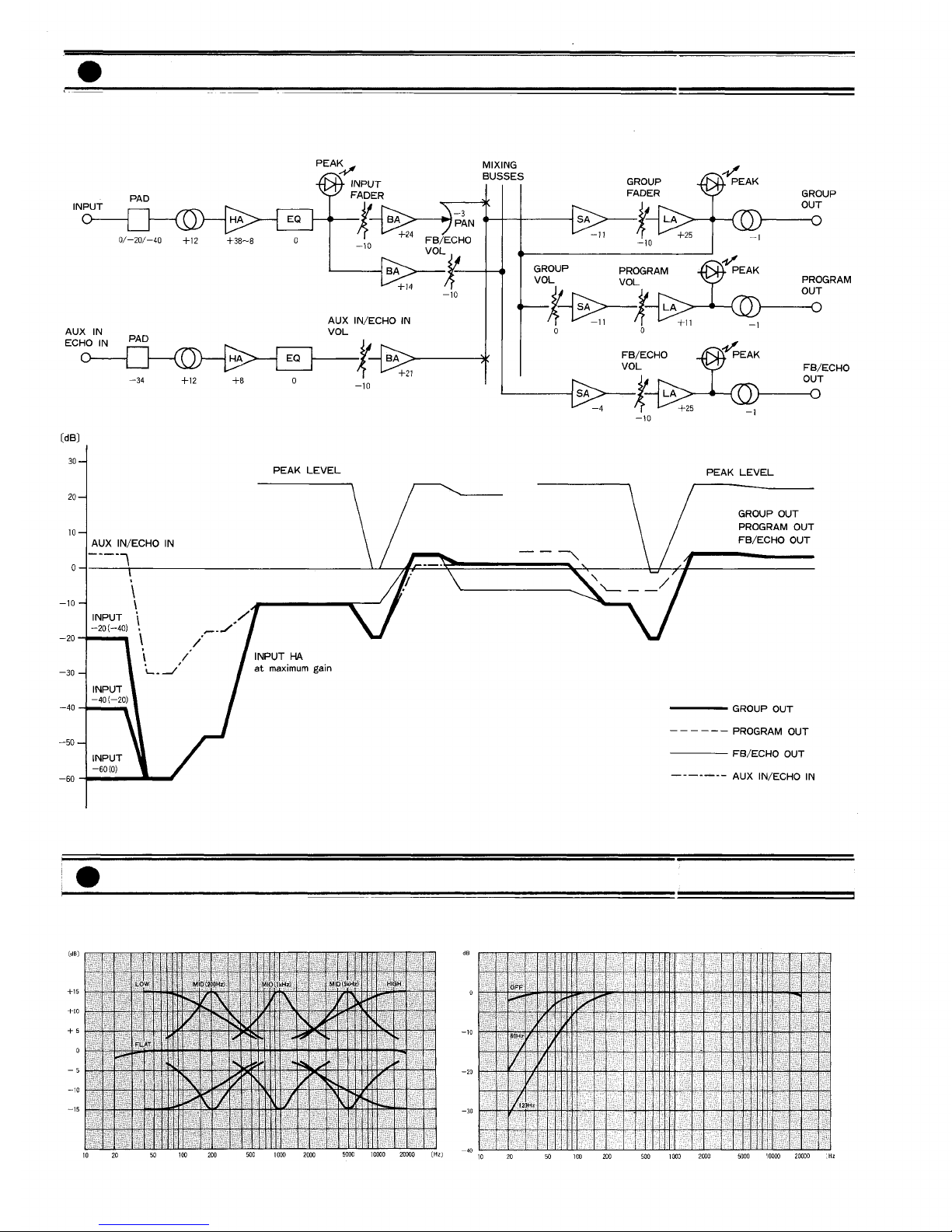
Equalization (CH IN, AUX IN, ECHO IN)
LOW 100Hz Shelving (±15dB maximum)
MID 200Hz to 5kHz, variable Peaking (±15dB maximum)
HI H 10kHz Shelving (±15dB maximum)
High Pass Filter
12dB/octave roll off switchable for 3dB down at 60Hz or
120Hz
Oscillator/Generator
Switchable sine wave at 400Hz, 1kHz and 10kHz (1.0%
Total Harmonic Distortion at +4dB* output) or pink noise.
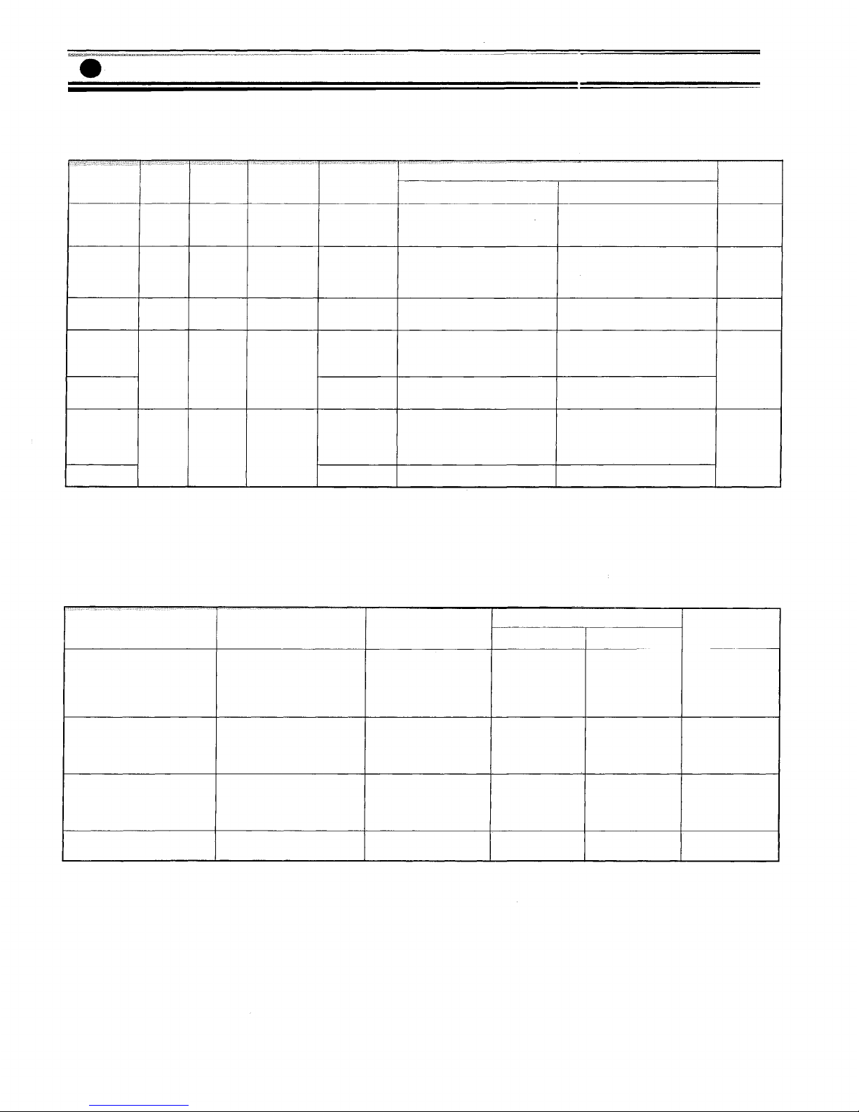
Inputs and Outputs
See accompanying tables of Input Characteristics and
Output Characteristics.
Crosstalk
-60dB at 1kHz, input to output
VU Meters (0VU = +4dB* output)
RX-7-164
4 large, illuminated meters; switchable for roup or
Program
3 smaller, illuminated meters; switchable for 2 Foldback or 2
Echo and CUE or TB
RX-7-248
4 large, illuminated meters for roup
4 large, illuminated meters, switchable for Program 1—5,
2—6,
3—7,
and 4—8
3 smaller, illuminated meters; switchable for 2 Foldback or 2
Echo and CUE or TB
RX-7-328
4 large, illuminated meters for roup
4 large, illuminated meters, switchable for Program 1—5,
2—6,
3—7,
and 4—8
6 smaller, illuminated meters for 2 Foldback, 2 Echo, CUE
and TB
Peak Indicators
LED built into each input turns on when the pre-Fader level
reaches 10dB above nominal.
LED built into each roup, FB, Echo and Program Out turns
on when the output level reaches 10dB above nominal.
Phantom Power
48V DC is applied to balanced input transformers for
powering condenser microphones.
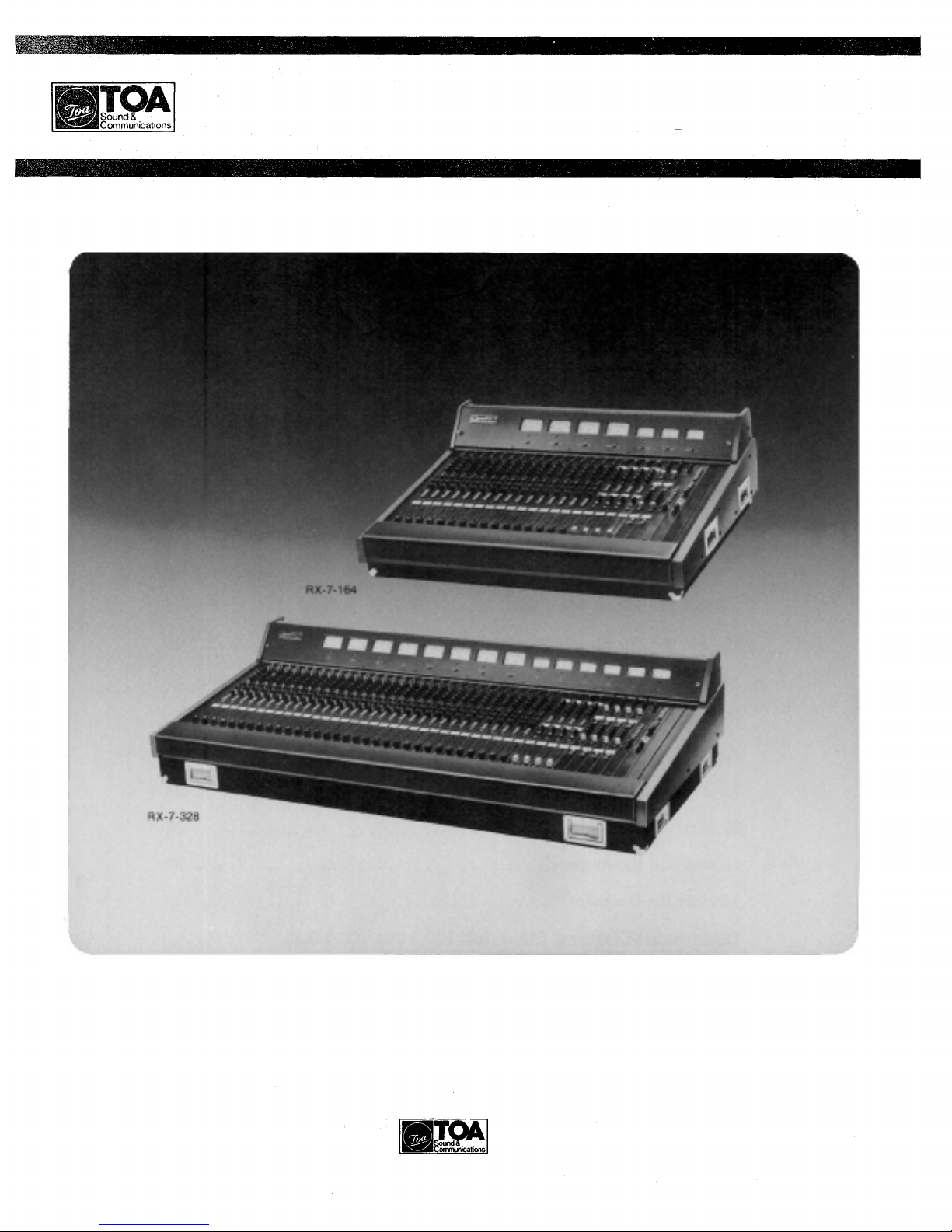
Finish
Black panel, rosewood trim, padded armrest
Dimensions W×D×H)
RX-7-164
40-3/8" × 32-3/8" × 13-7/8" (1026 × 822 × 353 mm)
RX-7-248
55-5/8" × 33-1/4" × 15" (1412 × 843 × 382 mm)
RX-7-328
66-5/8" × 32-3/4" × 15" (1691 × 833 × 382 mm)
Weight
RX-7-164; 78kg (171 pounds)
RX-7-248; 109kg (240 pounds)
RX-7-328; 138kg (303 pounds)
Power Consumption
RX-7-164; 120VA maximum
RX-7-248; 145VA maximum
RX-7-328; 170VA maximum
Accessory
Talkback Microphone
*0dB is referenced to 0.775V RMS
— 6 —
Input & Output Specifications
**All XLR connectors are floating (balanced) and transformer-isolated.
TRS phone jacks are unbalanced.
Sensitivity is the level required to produce a nominal output of +4dB (1.23V), or the specified nominal output
level if other than +4dB.
RX-7 OUTPUT CHARACTERISTICS
Connection
ROUP OUT 1—4
PRO RAM OUT 1—4 or 1—8
F.B. OUT 1 & 2
ECHO SEND 1 & 2
T.B.
OUT
ACCESSORY (SEND)
INPUT 1—16
1—24
or
1—32
ROUP 1—4
CH IN
(DIRECT OUT)
PHONES OUT
(L&R)
(HEAD) PHONES
Actual Source Impedance
80 ohms
110 ohms
110 ohms
For Use With Nominal
600 ohm Lines
10k ohm Lines
10k ohm Lines
8 ohms or higher
impedance lines
Output Level*
Nominal
+4dB (1.23V)
+4dB (1.23V)
+4dB (1.23V)
-10dB (250mV)
MAX Before Clip
+24dB (12.3V)
+24dB (12.3V)
+24dB (12.3V)
+10dB(2.5V)
Connector**
XLR-3-32 type
TRS Phone Jack
TRS Phone Jack
TRS Phone Jack
*0dB is referenced to 0.775V RMS.
**All XLR connectors are floating (balanced) and transformer-isolated.
TRS phone jacks are unbalanced except headphone jacks, wired Tip=Left, Ring=Right, Sleeve=Common
POWER SUPPLY UNIT RPS-7) SPECIFICATIONS
AC Line Voltage
AC mains 50Hz or 60Hz
DC Output Voltages
±21.5V (for amplifier circuit) 1.8A
+12V (for relay and LED's) 2.7A
+48V (for phantom power) 0.17A
+6V (VU meter lamps) 1.6A
Power Consumption
170VA maximum
Dimensions W×D×H)
21-1/8" × 14" × 7" (538 × 355 × 179 mm)
Weight
18kg (40 pounds)
Accessories
Power cord
Umbilical cable
— 7 —
SUB IN 1-4
AIR
MONITOR
L&R
TALK BACK
IN
ACCESSORY
(RCV)
INPUT 1—16,
1—24
or
1—32
ROUP 1—4
2.5k ohms
4.5k ohms
20k ohms
600 ohm lines
50 to 600
ohms mics
10k ohms
lines
-6dB (390mV)
-70dB (0.25mV)
-80dB (0.08mV)
-16dB (123mV)
-6dB (390mV)
Input Level*
Nominal
B (0.78mV) to -30dB (25mV)
B (7.8mV) to -10dB (250mV)
B (78mV) to +10dB (2.5V)
B (1.23V)
+4dB (1.23V)
-70dB (0.25mV) to -40dB (7.8mV)
-60 dB (0.78mV)
+4dB (1.23V)
+4dB (1.23V)
MAX. Before Clip
-26dB (39mV) to +4dB (1.23V)
-6dB (390mV) to +24dB (12.3V)
+14dB (3.9V) to +24dB (12.3V)
+24dB(12.3V)
+24dB (12.3V)
-36dB (12.3mV) to -6dB (390mV)
-26dB (39mV)
+24dB (12.3V)
+24dB (12.3V)
Connector**
XLR-3-31
type
XLR-3-31
type
XLR-3-31
type
XLR-3-31
type
TRS
Phone Jack
*0dB is referenced to 0.775V RMS.
S
Connection
INPUT
1—16, 1—24,
or
1—32
AUX IN 1 & 2
ECHO IN
1&2
Level
Switch
-60dBm
-40dBm
-20dBm
Actual
Load
Impedance
1.2k ohms
1.7k ohms
1.7k ohms
2.5k ohms
For Use
With
Nominal
50 to 600
ohms mics or
lines
600 ohm lines
Sensitivity*
-80dB (0.08mV)
-60dB (0.78mV)
-40dB (7.8mV)
-16dB (123mV)
-60d
-40d
-20d
+4d
RX-7 INPUT CHARACTERISTIC
Characteristics Diagrams
EQUALIZER CURVES
FILTER CURVES
Level Diagrams
Fig.
1)
Fig.
2)
— 8 —
1. XLR type INPUT connector is balanced, transformer-isolated and accepts low impedance
sources from -60dB to +10dB. Proper adjustment of both the INPUT LEVEL Switch and
TRIM Knob make it possible to provide the optimum setting for each input.
2. ROUND ( ND) LIFT Switch is for Pin 1, which makes it easy to avoid ground loops
that are often caused in connection with other equipment and that may induce hum noise.
Sliding the ground lift switch from the NORMAL position to the LIFT position cuts
ground loops and may reduce hum noise. For most applications it should be set to the
NORMAL position.
3. ACCESSORY SEND/RECEIVE (ACCESSORY) jacks are unbalanced with an impedance
of 10k ohms and a nominal level of +4dB. These jacks allow inserting signal processing
devices into the signal path. The regular signal path is interrupted at the RCV jack by
inserting a plug into it.
4. DIRECT OUT jack is unbalanced with an impedance of 10k ohms and a nominal level of
+4dB. The jack delivers the signal prior to the pan pot and bus assign switches.
5. PHANTOM power switch permits the user to supply 48V DC through the input connector
to a condensor microphone. If phantom power is required, the phantom power master
switch on the rear panel of the Power Supply Module must be ON before the phantom
power switch on each Input Module is turned ON.
6. PHASE switch reverses the polarity of the incoming audio signal. At "N" (normal)
position, Pin No. 3 of the XLR connector is hot and Pin No. 2 is low. At the "R" (reverse)
position, Pin No. 2 is hot. Slide the phase switch to the appropriate position to match the
polarity of the source. Polarity can often be intentionally reversed to eliminate leakage
from adjacent microphones or to create special acoustic effects.
7. INPUT LEVEL switch has 3 settings, -60dB, -40dB and -20dB at the "0" position of the
TRIM knob. Adjust the input level switch, depending on the output level of microphones
or associated equipment.
8. TRIM knob varies the gain of a head-amplifier and provides a continuously variable
control of gain in the range of 0 to —30dB from the input level switch position. It permits
optimum setting of the input channel gain and provides good S/N ratio when used in
conjunction with the INPUT LEVEL switch. Another use of the trim knob is to allow
every input fader to be in a horizontally straight line with proper adjustment of the trim
knob.
9. EQUALIZER consists of three frequency ranges. The HI H and LOW shelving type
equalizers provide 15dB of boost and attenuation at 10kHz and l00Hz, respectively. The
MID equalizer employs peaking type equalization which provides 15dB boost and
attenuation. The MID-EQ center frequency can be easily set at any frequency between
200Hz and 5kHz by use of a continuously variable frequency setting knob. The "0"
position of each equalizer provides flat response.
10. EQUALIZER IN/OUT switch puts the input signal either in circuit or out of circuit of the
equalizer. The OUT position provides flat response no matter what the position of the EQ
controls.
11. HI H PASS filter switch provides flat response when OFF, but can be set to cut the
frequency response either below 60Hz or below 120Hz at a 12dB/octave rate.
12. FOLDBACK knobs provide for two independent foldback mixes. The No. 1 foldback knob
mixes the signal pre-fader, but the No. 2 foldback knob is associated with the Pre-Post
fader selector switch which permits its mix to be either Pre or Post fader.
Input Module IPM-7)
Fig.
3)
— 9 —