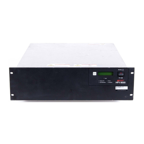
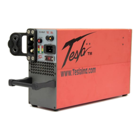
Technix SR10OKV-5KW User manual

t
ti
I
I
t
l]
t
I
t
t
I
I
L]
LJ
tr.
LJ
IJ
li
OPERATOR MANUAL
Model: SRí0OKV-5KW
S/N: DU16-112131
U
t
I
2

INDEX
1 GENERALINFORMATION.......
2 TECHNICALSPECIFICATIONS
3 DESCRIPTION...
3.1 Front panel
3.2 Rear Panel
4 INSTALLATION
4.1 Preliminary
4.2 Mains Power connections ..............
4.2.1 For 230 V one phase models (max power 1200W)...
4.2.2 For 400 V 3 phases 3HU models ..............
4.2.3 For 400 V 3 phases sHU, 7HU, 10HU and cabinet models
4.3 Recommended fuses and wire sections
4.4 High Voltage Connection.............
5 OPERATING.....
5.1 Switching-on
5.2 Setting v"lr"t'¡n'lå;;¡ ffioe::
5.3 Release....
5.4 Starting High Voltage delivery.
5.5 Stopping High Voltage delivery
6 OTHERFUNCTIONS......
6.1 OCL/OCP function
6.2 Arc detection function (SR models only).......
6.3 lnhibit function
6.4 Using HV-On lnstruction and HV-Off lnstruction.
6.4.1 Using HV-On lnstruction and HV-Off lnstruction in Safety Mode
6.4.2 Using HV-On lnstruction and HV-Off lnstruction in Easy mode..
6.5 Remote Control Mode
7 RS 232 COMMUNICATION PROTOCOL
7.1 Communication princip|e...................
7.2 ASCII protocol
7.3 Structure of an instruction .................
7.4 Shape and transmission rate.............
7.5 SUB-D connection
7.6 Listing and description of instructions
Diagrams
Maximum Frequency
Use and safety
11
11
12
12
12
13
13
7.7
7.8
7.9
20
..,,,,,,',,,20
............2Q
.,,.'.''''''20
,,','.'.''''20
'.'',,,...,,20
',',,,,.....21
............23
............24
.'.'...'.,,,24
3

8 RS232.OPTICAL FIBER INTERFACE
9 MAINTENANCE AND TROUBLESHOOTING
9.'1 Filters cleaning
9.2 Trouble shooting
Appendix - Synoptics..
Appendix - Triphase
24
25
25
26
27
29
L
4

I GENERAL INFORMATION
As this generator will deliver High Voltage, it has to be installed and used by a
competent staff who have a good acknowledge of the rules on property and people
security concerning High Voltage.
Ground connection has to be made by competent people according to the appropriate
rules. ln particular, we recommend braid cables.
For the machines delivered in cabinet presentation:
Opening the cabinet is only possible by using the key which was delivered with.
This key and the documentation of the machine must be kept by the authorised and
competent responsible who has to manage their use
Before any use of the generator, it is strongly recommended to read carefully the
present manual.
We decline any responsibility for damage and injuries caused by improper use or
improper installation or accident or non authorised repair.
Any damage resulting from one of these cases would not be supported by the
Warranty.
ln particular, any damage resulting from an electrical network which is disordered
(surge, overvoltage, lightening etc...) will not be supported by the warranty.
It is strongly recommended to read the framed texts.
- Warranty is not supported if the strap of protection on the top of the cabinet is cut
- The information contained in this manual can change without notice.
Following symbols are present on your machine.
Here is their meaning:
Be careful danger: Risk of Electricity shock
Be careful: Risk of Danger
5
t
I 0v02. I 9

2 TECHNICALSPECIFICATIONS
2.1 Electrical Specifications
Output Voltage From 0 to 100 kV
Output Current From 0 to 50 mA
Polarity Negative (prior to earth)
Mains Voltage : 400 VAC t 10 o/o 47 - 63 Hz 3ph + Earth
Any damage resulting from an electrical netvvork which does not
respect fhese specifications will not be supported by the warranty.
lnput Power 5.8 kW
Voltage regulation Load Regulation < t 0.05 % of full voltage (0 - 100 % load)
Line Regul < + 0.05 % of full voltage(Mains Voltage x 10 %)
Load Regulation < t 0.05 % of full current (0 - 100 % load)
Line Regul < 0.05 % of full current (Mains Voltage x 10 %)
Current regulation
Ripple + Noise < 0.1 % RMS
Stability : 0.01 o/o lhour, 0.03 % / I hours
after one hour of warm up with constant load & ambient temperature
Settling Time <100 ms
Efficiency at full load 92o/o
2.2 Other specifications
Cooling by air (fans)
Operating Temperature : 0 to 40'C
Storage Temperature : -2Q to 60'C
Humidity 0 to 80 o/o at 25 oC, 50 o/o at 40'C (no condensing)
Format
t
t
6
10v03.23
Rack 7U-19" H311 x L483 x P600 mm

3 DESCRIPTION
3.1 Front panel
Mains power ON/OFF switch
It allows switching on and off the generator
@ ^"r switch (06)
(this function is not available with no-instrumented models)
It provides the following additional safety: when this switch is in vertical position (ON
position), the generator will never deliver HV.
Therefore, in this position and without the key, it is not possible to make the generator
running in LOCAL and in REMOTE mode.
@ nu-off Push button
By pushing this button, generator stops to deliver HV
@ nu-on tndicator
When this led is ON, it indicates generator is not delivering HV
Hv-On Push button
By pushing this button, the generator delivers HV when all conditions are respected
Hv-On Indicator
When s led is ON (illuminated), it indicates generator is delivering HV
Mains power Indicator
When this led is ON, it indicates mains power is present.
Fault lndicator
When this led is ON, it indicates a fault has been detected
For more details, see: $ OPERATING / Release
@ tnterlock Indicator
When this led is ON, it indicates lnterlock contact is open.
For more details, see; $ DESCRIPTION / Rear Panel / lnterlock
I
o
E
HU
trf,
HU
kuâ
High Uoltage Pouer Supplg
Cur rent
uol 1ðge
Sðle Lock I
E
Preset
EI
oc¡
ocP
ELiæ
elr
7
17v02.12

iRemote Gontrol lndicator
When this led is ON, it indicates the generator is remote controlled.
For more details, see; $ OTHER FUNCTIONS / Remote Control Mode
@ ocr-loGP Push button
(in CCR models only OCL mode is available)
By pushing this button, you change the Over Current mode.
For more details, see; $ OTHER FUNCIIONS / OCUOCP
This button is neutralized for CCR models.
OGL lndicator
in CCR models)(always
When this led is illuminated, it indicates the generator is in Over Current Limitation Mode.
@ oce tndicator
(always turned Off in CCR models)
When this led is illuminated, it indicates the generator is in Over Current Protection Mode
Preset Push button
By pushing this button, the setting values of Voltage and Current are indicated on the
displays (13) and (16).
Voltage setting potentiometer
This 10 turn potentiometer (resolution < 05%)allows to set the Output Voltage value.
Voltage Display
This display indicates either the Setting value of the Voltage or the actual value of the
Voltage delivered by the generator.
A3y2 digit display is generally used for standard models.
Voltage Regulation lndicator (SR and LPR) / End of Gharge (CCR)
SR and models: when this led is turned on, it indicates generator is Voltage regulating
CCR models: when this led is turned on, it indicates End Of Charge has been reached
Current Display
This display indicates either the Setting value of the Current or the actual value of the
Current delivered by the generator.
A3% digit display is generally used for standard models
Gurrent Regulation lndicator (SR and LPR)/ Charging indicator
SR and PR models: when this led is turned on, it indicates generator is Current regulating
CCR models: when this led is turned on, it indicates generator is Charging
Gu rrent setting potentiometer
I
I
This 10 turn potentiometer (resolution < 0.5%) allows to set the Output Current value

3.2 Rear Panel
@ nign Voftage output
HV cable has to be plugged into this Output.
Additionnal High Voltage Output
This output can exist on some models: reversible polarity generators or floating output
generators (see $ OPERATING).
SubD 9 pins *
Used to drive the generator through a RS232 or a Profibus connexion. Only available with
RS232 or Profibus option.
For more details, see; $ INTERFACE SELECTION
@ n"rote Control Connector
This SUBD 25 pins (15 pins in option) connector allows the generator to be remote controlle
(see $ "OTHER FUNCTIONS").
(
,i
I
lnglod(:
pin 16 @eded
b pan21
@
@
@
aÂ,å-å?,?'i?:
a.r.eoov @
su+k
@
o
LJ
TEC
LP
(9
@
AA
@
0
@
RS232
I
B
ô
Remole
o
Jl
ö
Tx
@
@
@
@
o
9

Jl Gonnector *
Not with standard models.
lnterlock
The generator can produce HV only if the 2 pins of this connector are connected (dry
contact).
Depending your unit configuration, the lnterlock can be a 2 points Lemo type shaped or
integrated in the remote SubD connector.
Default is the connector to close the lnterlock loop.
User is advised to integrate this loop into a global security system.
The cable of lnterlock connection has mandatorv to be shielded.
@ n.l+s Gonnector *
Used to drive the generator through an Ethernet connexion. Only available with Ethernet
option.
For more details, see: $ INTERFACE SELECTION
@ ctound Bolt
This bolt is connected to the ground of the generator chassis.
It allows realizing external connections to the ground of other devices.
@ u"in" Power Connector
It allows the connexion to the mains power
@ U"""urement feedback from HV Tank *
Ensures the measurement feedback between the tank and the control rack. Only generators
with external tank (means not integrated in the rack)are concerned.
Arcs Counting Dipswitch *
Allows to activate or deactivate and set the arcs counting function (number of arcs).
Only available with arc counting option.
For more details, see; $ARCS; DETECTION AND COUNTING
GPIB "
Used to drive the generator through aGPIB bus (IEEE 488). lncludes the GPIB address
setting dipswitch.
Only available with GPIB option.
For more details, see; $ IEEE 488-2 COMMUNICATION PROTOCOL
Optic Fiber
Used to drive the generator through a R232 interface over optic fiber.
* can change regarding models
t
t
10

4 INSTALLATION
4.1 Preliminarv
General Safetv Precautions
This generator contains hazardous voltage and energy.
It can only be used by a qualified personnel correctly trained and experimented on
Electricity and High Voltage dangers and who read carefully ffirc user's manual.
Before connecting input AC power, make sure that all covers are fastened and that
grounding and cooling are properly realized.
Never use the generator in a manner not described in this manual.
Never manipulate HV output cable when the generator is operating.
Use extreme caution when connecting output HV cable.
Make sure that all load capacitors are completely discharged before any connection.
Never remove the labels DANGER or WARNING. Replace them immediately if necessary
When replacing fuses, don't ever change their type, voltage or current features.
Orientation
The generator has to be oriented in horizontal position (indications have to be read from left
to right and from up to down).
Coolinq Requirements
Enough clearance must be provided for a correct air flow and cables free passage.
We recommend a minimum of 20 cm of clearance at the front and at the rear of the machine.
ln all cases, and in particular when the machine is operating in a closed system, installer has
to make sure that the temperature of inlet air does not exceed 40'C.
This sometimes requires an additional cooling system is required when external temperature
exceeds 40 "C.
4.2 Mains Power connections
1- Before connecting to mains power, make sure the mains power switch (01) is in
position O (open position).
2- Earthed-neutral system (TN) or Earth-earth (TT) system only can be used.
lnsulated Earth system (lT) is strictly prohibited and can seriously damage the
generator.
Warranty will not be supported for any damage resulting from a connection of
the generator with an lnsulated Earth system (lT).
Please contact our technical service if you have any question
WARN¡NG!
t
I
11

E
mt
€F
4.2.1 For 230 V one phase models (max power 1200W)
The mains power connection is made with the standard CE22 cable (24)
delivered with the machine.
You can use a brass screw (25) connected to the chassis to realize ground
connections to external devices.
Generator is protected by 2 fuses located inside the CE22 connector.
4.2.2 For 400 V 3 phases 3HU models
The connection with the electrical network is made by using the 4 pin female
connector (24): pins 1, 2 and 3 must be connected to the three phases and pin 4
must be connected to ground.
You can use a brass screw (25) connected to the chassis to realize ground
connections to external devices.
The neutral phase is not used.
Generator is protected by 3 internal 5 x 20 Gg model fuses.
L
t
4.2.3 For 400 V 3 phases SHU. 7HU. 1OHU and cabinet models
The connection with the electrical network is made by using the Feed{hrough
terminals (24): the three phases must be connected to the grey terminals and the
ground must be connected to the yellow and green terminal.
A case guides and help keeps the main cord (where applicable see Appendix
"lnstalling the Three-Phase Case").
You can use a brass screw (25) connected to the chassis to realize ground connections to
external devices.
The neutral phase is not used.
Generator is protected by 3 internal 10.3 x 38 Gg modelfuses.
Note: There is no particular order to wire the 3 phases
)
ao
For safety reasons,
When connectinq to the electrical network: First connect the earth screw (25). Then,
connect the conneclor (24).
When disconnectinq from the electrical network: First disconnect connector (24). Then,
disconnect the screw (25).
WARNING!
I 5v02.06 t?

Mains Connector
Model
CE22
9206 14V from ICT 2
Feed{hrough terminals
BUS BAR
Recommended
wire section
1.5 mm'
2.5 mm2
4 mm2
6 mm2
10 mm2
16 mm2
25 mm"
Recommended
fusest
2x3.154
2x5A
2x10⁴
3x5A
3x10⁴
3 x 124-16Á.
3x204
3x254
3 x 324-404
3 x 404-504
3x634
3 x 804-1004
Generator Power
300 W or 150 Jis
600 W or 300 J/s
1200 W or 600 J/s
1500 W or 750 J/s
3 kW or 1.5 kJ/s
5 kW or 2.5 KJ/s
8 kW or 4 kJ/s
10 kW or 5 kJ/s
15 kW or 7.5 kJ/s
20 kW or 10 kJ/s
30 kW or 15 kJ/s
40 kW or 20 kJ/s
¡Q
o0)
(Ðc
ñro
ào
Om
rf"
4.3 Recommended fuses and wire sections
Following table indicates the fuses and wire sections which are recommended for connection
of the generator to the user's electrical network:
4.4 Hiqh Voltaoe Gonnection
For fixed polarity generators, High Voltage connection is made on rear panel with the HV
cable (32) delivered with the machine.
The ground is internally connected to the chassis.
For reversible polarity generators or Floating output generators, see S "OTHER FUNCTIONS
/ Floating Output Generator" and S S "OTHER FUNCTIONS / Reversible Output Generator".
r dowacting model
I
i
t
WARNING!
Please make sure before switching-on mains power that the male HV connector is
plugged in the female connector.
Any damage resulting from a non-respect of this condit¡on will not be supported by the
warranty.
For generators delivering 50 kV and more:
1- HV connector of the cable has mandatory to be lubricated each time it is plugged.
Othen¡vise it can occur electrical flashes which may damage the generator.
A lubricant tube is delivered with the machine (8431 grease from Rhone Poulenc)
2- Please make also sure that both females sockets fixed on the machine and males
connectors of the cable are always very clean. Any damage resulting from a non-respect
of these conditions will not be supported by the warranty.
I
t
I 5v02.06 13

t
L
5 OPERATING
5.1 Switchinq-on
When all above instructions are completed, generator is ready to be switched-on by pushing
the Mains Power ON/OFF Switch ( 01 ) located on front panel : position I
ln these conditions, the generator is ready to work.
lndicators present the following status :
Hv-Off lndicator (021: llluminated.
Hv-On lndicator (03): Not illuminated.
Mains Power lndicator (04): llluminated.
lf this led is OFF, this means one of the three phases is missing or that the electrical network
is not in accordance with the generator (example: 3x220 V instead of 3x380V). ln this case,
please check the generator connection to the mains power.
lnterlock lndicator (05): Not illuminated.
lf this led is ON, this means external safety system is open and the lnterlock adapter (20) on
the rear panel is not plugged.
Fault lndicator 109): llluminated
This led indicates that no fault has been detected when switching-on.
For more details, see $ "OPERATING / Release".
Remote Control lndicator (11):
This led is ON when the generator is remote controlled and OFF if it works in local mode
For more details, see $ "OTHER FUNCTIONS / Remote Control Mode".
OGL lndicator (08): llluminated.
OCP lndicator (39): Not illuminated.
Voltaqe Requlation lndicator (14): Not illuminated.
Current Requlation lndicator (15): Not illuminated.
Voltaqe Displav (1 3): Functionning.
Current Displav (16): Functionning.
5.2 Settins Values in Local Mode
Output Voltage and Current can be set by using the 10 turn potentiometers (1 2 & 17) located
on front panel.
By pushing the Preset Button (10), the displays (13 & 16) indicate the setting values of
Voltage and Current.
At this step, the generator is not yet delivering HV.
llvll.l4 I4

t-
5.3 Release
By pushing Hv-Off button (02), you release the different status and the generator is waiting
for delivering HV.
At this step the Fault led (09) must be OFF.
This operation can also executed in Remote Control Mode.
lf the Fault led remains ON, despite pushing Hv-Off button, this means the generator
presents one of these problems:
1- lnterlock loop is open: lnterlock connector (20) is not correctly bolt or is not short circuited.
2- Mains voltage is not in conformity
3- The generator is on OCP mode with a too heavy load
4- Ambient temperature is out of specifications
5- lnternal defect.
ln this last case, contact our Technical service.
For more information, see the "Troubleshooting" paragraph at the end of the manual.
WARNING!
SR and LPR models are designed in order to support a limited number of arcs (CCR
models are not concerned).
ln the case it occurs more than 1 arclsecond in your application, you must add an external
protection resistor.
Please contact our technical service to define the features of this external resistor.
lf this recommendation is not performed, your generator should be damaged and the repair
resulting will not be warranty covered.
5.4 Startinq Hish Voltaqe deliverv
When pushing Hv-On button (03), the generator starts to deliver HV:
Hv-On led (03) lights on and Hv-Off led (02) lights off.
The generator delivers the Voltage or the Current defined by the setting values.
Voltage Regulation led (1a) orCurrent regulation led (15) lights up depending on the load and
the setting values.
For models provided with the key switch (06) on front panel, this switch has to be in horizontal
position (ON position).
lf this switch is vertical position (OFF position), the generator will not deliver HV.
5.5 Stoppinq Hish Voltaqe deliverv
For stopping at any time HV delivery, push Hv-Off button (02):
Hv-Off led (02) lights on and Hv-On (03) lights off.
For security reasons, Hv-Off has always priority whatever is the control mode (LOCAL or
REMOTE).
L-
t
14v06. l9 15

I6 OTHER FUNCTIONS
6.1 OCL/OCP function
OCL/OCP push button (07) allows you to choose between two modes:
OCL Mode (Over Current Limitation): in this mode, the current is regulated according to the
setting. This mode is generally used for capacitive loads.
OCP Mode (ln Over Gurrent Protection): in this mode, the generator is stopped as soon as the
output current is higher than the current setting. ln this case the generator becomes in fault.
Remarks:
1- OCP mode is inoperative for chargers (CCR models).
2- When charging a capacitor with SR or LPR model, OCP mode is not recommended. Please
use OCL mode only.
6.2 Arc detection function (SR models onlv)
As soon as an arc is detected, the generator stops High Voltage delivery during a period
called Tsrop. This is factory set at 100ms.
First arc occurrence Second arc occurrence
HV Output
Arc detection (internal information)
High level +Tsrop = 100ms +T srop = 100ms
Low
6.3 lnhibit function
lnhibit function is available on the remote connector (23) located on rear panel.
It allows the generator to be inhibited when it is working (in local mode or in Remote mode).
ln other words, the generator does not deliver anymore High Voltage as long as the lNHlBlT
signal is active (in condition, however, that Hv-On has been activated as shown in following
diagrams).
lnhibit is indicated by simultaneous light on of Hv-On led (03) and HV-Off led (02).
Hv on lnstruction
Hþh Leel 2
Low Lwel
Hicù Level¿
Lorl Lwell
From +5V to +24V
ov
HV De¡¡Y€ry
t{o HV Delivery
t
¿200ms
tructionHV Off lnr
TI
lnhibit
iPin 2i
HV Output
r Free 2 Conneqted to ground (+24Vwhen Reley Interfacef
T6

6.4 Usinq HV-On lnstruction and HV-Off lnstruction
6.4.1 Usinq HV-On lnstruction and HV-Off lnstruction in Safetv Mode
HV On lnstruction
lügh ¡.cvdr
tow lcüed I1200m¡
t
lfthlclrCt
lowl.evCr
llV De{ivery
to llV De$very
StfEl Stt63 SltGg Stàt63.nd/t st*62
St.t65 St-t6l
r F¡ee I Connected to gromd {+2AV when Reþ lmcrfæe}
Status 1: Hv-Off lnstruction is at low level: HV cannot be delivered
Status 2: Hv-Off lnstruction, HV waits for Hv-On lnstruction reaching high level to be
delivered
Status 3: Hv-Off lnstruction, HV On lnstruction are at high level: HV starts to be delivered
Status 4: Hv-Off lnstruction is at high level, HV still delivered after Hv-On lnstruction reached
low level.
Status 5: Hv-Off lnstruction is at low level, HV stops to be delivered
REMARK: in case of conflict between Hv-Off lnstruction and Hv-On lnstruction, Hv-Off
lnstruction has always priority and Output HV is not delivered.
6.4.2 Usinq HV-On lnstruction and HV-Off lnstruction in Easv mode
This consists to keep Hv-On lnstruction always at high level and switch HV delivery with HV-
Off lnstruction.
HV On lnstruction
Hþh twelz
lowLeYelr
HVOfrlnctruGtion
}lþh Lwelz
lowLwel1
HV Delivery
f,o llV Delivery
r Free 2 C¡nne¿ted toground (+24Vwhen Reþ lnterfacel t t e [2ü]mr; -¡
t
t
StafGl
t
t
tt
>2(þm¡
HVOfrlætrt¡ct¡on
HVOutput
HVOutput
I7

6.5 Remote Gontrol Mode
The generator can be remote controlled if the connector (23) is plugged following the pin-
out indicated below and if pin 8 is connected to ground.
As soon as the connection is done, Remote Control led (1 1) lights up.
Operating in Remote Control mode is the same as in Local mode.
ln this mode, all local resources are inoperative except:
- Reading the setting values with Preset push button (10)
- Voltage display (13) and Current display (16)
- Stopping HV delivery is always possible by pushing HV off button (03).
Pin-out & description of SUBD 25 pin female connector (23) located on rear panel:
(only available on standard models without GPIB options)
r/o
lnput
Output
Output
lnput
Output
Output
lnput
lnput
Output
Output
Output
Output
lnput
Output
Output
lnput
Output
Output
Output
lnput
Output
Siqnal Description
croduced by a fleeting openinq ofthe ground (pin16)
Fault information
0V = Fault:+15V** = no default
Open lnterlock information
0V = open; +15V** = Closed
produced by a fleeting closure to the ground (Pin16)
0 to j0 V = 0 to 100% of output voltage
0 to 10 V = 0 to I 00% of output current
Activated by a +5V to +24V signal
Activate when this pin is connected to ground ( Pin16 )
0V = Mains is correct ; +15V** = Mains is not correct
0V to 10V = 0 to 100% of the Output Power
(onlv on LPR and power requlated models)
0-10 V copy of the Voltage setting selected
with the front oanel ootentiometer
0-10 V copy of the Current setting selected
with the front panel potentiometer
Cutput current setting 0 to 10 V = 0 to 1 00%
+10,00V, 5 mA Max
0V Ground reference for digital signals
Output voltage setting 0 to 10V = 0 to 100%
0V = Current Regulation
15V"*= End of charge (CCR) or Voltage Regulation (SR or LPR)
0V = HV off; +15V** = HV on
lV Ground reference for Analog signals
lnterlock order : Connect this pin to Digital Ground (pin 16) for
closing lnterlock
Except for models with 2 points Lemo connector
+10,00V, 5 mA Max (LPR models)
Output power setting 0 to 10V = 0 to 100% (only with power
requlated models)
Signal
Hv-Off Control
Fault Monitor
lnterlock Monitor
Hv-On Control
Voltage Monitor*
Current Monitor*
lnhibit Gontrol
Remote Control
NC
Mains Monitor
Power Monitor*
lonlv on LPR or power requlated models)
Copy of Local Voltage
Settinq
Copy of Local Gurrent
Settinq
Current Setting
+1 0V Reference
0V Disital Ground Ref.
Voltage setting
Regulation Monitor
End of Charqe Monitor
Hv-On Monitor
0V Analog. Ground Ref.
NC
NC
NC
lnterlock Control
+10V Reference
Or Power Setting
Pin
1
2
3
4
5
6
7
8
I
10
11
12
13
14
15
16
17
18
19
20
21
22
23
24
25
* On a serial 470 A impedance ** +15 V limited to 10mA
*** Safety mode only (refer to $ Other Functions for easy mode)
The cable of REMOTE connection has mandatorv to be shielded and no longer than 3
meters.
18

Programminq example
For a 20 KV, 1500 W generator: Vmax = 20 KV,lmax = 75 mA.
Wished values: Output Voltage = I KV, Output Current = 60 mA.
Pin 17 (Voltage setting) has to be: 4 Volts and pin 14 (Current setting): 8 Volts.
The same scale for reading Output values:
A 10 Volts voltage on pin 5 (lmage of the HV voltage) will indicate the generator is delivering
20 kV and a 4 V voltage on pin 6 (lmage of the Current) will indicate the Output Current is 30
mA.
Manaqement of Voltaqe and Current settinqs in Remote Control
Two modes of control can be used:
1) Standard Remote Control
For Remote controlling Voltage and Current, an external 0-10 V signal has to be sent on pins
14 and 17.
2) Control bv front oanel
For setting Voltage and Current from the potentiometers located on front panel, following
connections have to be realized:
- pin 12 to pin 17 for Voltage
- pin 13 to pin 14 for Current
t
f
t
L
t
REU:
Sheel:1/1
ó/8 rue Eugéne Oupuis
ZAC EMPÂM 9tA6ø CMTETL_FRffiE
1 ê1. øl -56-71 -2A- 6ø F ðx. øl -5ó-71 -28-69
uuu. technix-hv. coh
-/7-¿/
TECHNIX
TITLE: Ânalog Remore 25pts
Document Number:
Date= ø3/ll /2ø11 ø9? 32? 3ø
U
U
U
Example Remote Control llode Sudb 25pts
.+ l& Porsr¡sere.
blrære. <lOð)
k/ñãl Or lñpulse cont¡ct (zøAos i¡niruñ)
--Jì- brñål Clos€d Iñrlse .óræt (2&< 6iñil¡lÃ)
-
Wñål OFô turrch cñ(et
15v12.07 I9

7 RS 232 COMMUNICAT¡ON PROTOEOL
7.1 Communicationprinciple
User provides instructions to High Voltage Power Supply from a computer terminal (PC or
other operating system). These instructions are identified and interpreted by the inside
(L.A.B.TEC> (Laboratory Analog Board Technix).
The board executes the instruction and confirms to the user the instruction has been
executed by fonrvarding back to the user the same instruction wave form which was sent.
7.2 ASCII protocol
Communication is based on a question/answer principle. The computer sends on a line a
coded ASCII character followed by the parameters needed for the instruction. The board
answers immediately after reception and handling of the received characters.
For the instructions, messages are ended by the character CARRIAGE RETURN (CR -
ASCII 13 code).
For the answers, messages are ended by the character CARRIAGE RETURN (CR - ASCII
1 3 code).
7.3 Structure of an instruction
Function structure: an ASCII character, followed by one or several parameters of the function
(in the case of several they have to be separated with a comma), and at last a termination
character.
Answer structure: The previous string of characters which was sent + a string of ASCII
characters corresponding to the result, followed by a termination character.
7.4 Shape and transmission rate
1 start bit, I data bits, 1 stop bit, no parity
Full Duplex mode, bauds rate: 9600
7.5 SUB-D connection Shielded
9 pin Sub-D :
Pin 2: TxD,
Pin 3: RxD,
Pin 5: GND
25 oin Sub-D (with opticalfiber)
Pin 3: TxD,
Pin 2: RxD,
Pin 7: GND
1
2
3
¡
?
a
56
z
I
9
t
¡
l
{
5
L
t
Female
l4v0l.0l
r
Male
20

7.6 Listins and description of instructions
1) Output voltage programming
2) Output current programming
3) Output voltage monitor
4) Output current monitor
5) Hv-On
6) Hv-Off
7) Local/remote mode
8) lnhibit
9) lmage of the power supply logical status:
- regulation
- fault
- interlock
- Hv-On / Hv-Off status
NOTE: The input and output analogical information (voltage and current) are a 12 bits
resolution.
1) Output Voltaqe proqramminq
lnstruction: d1,X (X e [0 ;a095])
Answer: d1,X
2) Output Current proqramminq
lnstruction: d2,X(X e [0;a095])
Answer: d2,X
3) Output Voltaqe Monitor
lnstruction: a1
Answer: a1Z (Z e [0; 4095])
4) Output Current Monitor
lnstruction: a2
Answer: a2W (W e [0; 4095])
5) HV on
lnstruction: P5,1
Answer P5,1
6) HV off
lnstruction: P6,1
Answer P6,1
lnstruction: P7,0
Answer: P7,0
DELAY = 100 mS
DELAY = 100 mS
lnstruction: P5,0
Answer P5,0
lnstruction: P6,0
Answer P6,0
7) Local/remote mode
lnstruction: P7,1
Answer: P7,1 .---È Local Mode I
t
- Remote mode
?I
This manual suits for next models
1
Table of contents