TechnoKom TKLS User manual

TKLS • USER MANUAL 1
TechnoKom © 2014
FUEL LEVEL SENSOR
USER MANUAL
DOCUMENT
VERSION
1.11

TKLS • USER MANUAL
2
TechnoKom © 2014
Table of content
Software Copyright Notice .............................................................................................................................. 3
Safe Operation and Installation .................................................................................................................... 3
Introduction ............................................................................................................................................................4
Product Overview................................................................................................................................................ 5
Technical Specication...................................................................................................................................... 6
Scope of Supply................................................................................................................................................... 8
Components of Sensor ..................................................................................................................................... 9
Interface Connectors....................................................................................................................................... 10
Getting started ....................................................................................................................................................11
Sensor Connection .......................................................................................................................................... 15
Power Supply Connection ............................................................................................................................ 16
RS-485 (TIA/EIA-485-A) Bus Connection ............................................................................................ 17
Frequency Output Connection.................................................................................................................... 18
Auto calibration.................................................................................................................................................. 19
Error Codes......................................................................................................................................................... 22
Sensor Conguration...................................................................................................................................... 23
Driver Installation.............................................................................................................................................. 24
Modbus Register Mapping............................................................................................................................ 25
Appendix .............................................................................................................................................................. 26

TKLS • USER MANUAL 3
TechnoKom © 2014
Software Copyright Notice
Products of TechnoKom referred to in this Manual may incorporate software stored in
semiconductor memory or other media, copyrights to which belong to TechnoKom or third
parties. Laws of the Russian Federation and other countries secure certain exclusive rights
of TechnoKom and third parties to the software, which is subjected to copyright, for example,
exclusive rights for distribution or reproduction.
Therefore, any alteration, reverse engineering, distribution or reproduction of any software
incorporated in TechnoKom products, is prohibited to the extent provided by law.
Furthermore, purchase of TechnoKom products does not imply direct, indirect or other
granting of any licenses related to copyrights, patents and patent applications of TechnoKom
or any third party, except for an ordinary, nonexclusive free license for use, which is granted
in virtue of law upon each sale of the product.
The communication protocol between the AutoGRAPH Series on-board vehicle tracking
controllers and the TKLS fuel level sensors (AutoGRAPH Hardware Interface Protocol)
is considered to be condential information and intellectual property of TechnoKom. The
AutoGRAPH Hardware Interface Protocol (AGHIP) shall be transferred by TechnoKom to
integrators and software manufacturers only upon signing a Condentiality Undertaking.
Unauthorized distribution of the AutoGRAPH Hardware Interface Protocol is strictly prohibited.
Safe Operation and Installation
This section contains important information for effective and safe operation of TKLS fuel level
sensors. Please read the information below before using the sensor.
• Sensors with damaged insulation of conductive parts, testing probe and body must not
be used.
• Operational conditions of the TKLS such as electrical and environmental characteristics
and condition of measured liquid should t the requirements contained in this User Manual.
Otherwise, the manufacturer will not be responsible for sensor safety and functional
efciency.
• All connections should be made when the sensor and external devices to be connected to
the sensor are disconnected from the power supply.

TKLS • USER MANUAL
4
TechnoKom © 2014
This User Manual applies to the TKLS fuel level sensor (hereafter – TKLS, sensor) produced
by TechnoKom Ltd. It contains installation and connection procedures of the TKLS, as well as
its function and control.
This Manual is intended for specialists who are aware of the maintenance and installation
principles typical for motor vehicles and are procient in using the electronic and electrical
equipment of various vehicles.
To ensure the best performance of the TKLS, it should be installed and set up only by qualied
specialists.
The TKLS sensor can operate both as a part of a fuel monitoring system and as a part of a
eet management system. For proper operation of the TKLS sensor, the customer should be
aware of the operating principles of these systems as a whole, as well as understanding the
functions of its individual components
Introduction
IMPORTANT
All information on functions, functional capabilities and other specications related to TKLS fuel level
sensors, as well as all information contained in this User Manual is based on current data (at time of
writing) and is deemed to be valid as of the date of publication.
TechnoKom reserves the right to modify the information or specications without prior notice or
commitment.
VERSION HISTORY
This table provides a summary of the document revision.
Version Description Date
1.8 Added instruction on auto calibration 07/2015
1.8.1 Corrected auto calibration station diagram 07/2015
1.8.2 Added information about the empty/full tanks calibration 08/2015
1.9 Added the section “Sensor empty/full tank calibration”
Corrected the frequency output connection diagram 12/2015
1.10 Updated Modbus Register Mapping 02/2016
1.11 Updated sections “Sensor Connection”, “Sensor conguration” 07/2016

TKLS • USER MANUAL 5
TechnoKom © 2014
Product Overview
The TKLS fuel level sensor is designed to measure fuel level in a vehicle fuel tank and transfer
this information to external devices via one of the supported interfaces. The TKLS can be
used as a replacement of the factory-tted standard fuel level sensor or as an additional
sensor for fuel level monitoring.
The TKLS supports data transfer via RS-485 bus, in AGHIP, LLS and Modbus protocols, and
via frequency output as pulses proportional to measured fuel level, PWM signal or periodic
sequence.
In addition to fuel level, the sensor measures ambient temperature and sends the readings
to an external device.
Any device equipped with RS-485 which supports data exchange in AGHIP, LLS or Modbus
protocols can operate as an external device (for example, a level indicator or a eet
management device).
TKLS fuel level sensors support AGHIP protocol which is communication protocol between
AutoGRAPH hardware which enables transmission of additional data, as well as readings of
the sensor built-in inclinometer.
Also connected to AutoGRAPH eet management system, TKLS-L sensor is able to load a
new rmware and new conguration from remote server via GPRS.

TKLS • USER MANUAL
6
TechnoKom © 2014
Description Value
Output Interface RS-485 (TIA/EIA-485-A),
Frequency output
Protocols for RS-485 AGHIP1/ LLS / ModBus
Bluetooth (BLE) Yes
Built-in Accelerometer / Inclinometer Yes
Automatic calibration Yes
Self-diagnostic Yes
Error Report Yes
Remote Conguration via Bluetooth Yes
Remote Conguration via RS-485 Yes
Remote Firmware Update Yes
Logging Yes
Temperature Measuring2Yes
Digital Input, numbers 1
Frequency Output
Output Frequency Range, Hz 100…3000
Output Type Open collector
Maximum Load Current, mA 200
Measuring Features
Operational Liquids Gasoline, fuel oil
Level Measuring Accuracy, % ≤1
Resolution, bit 12
Temperature Measuring Range, °С -40…+85
Temperature Measuring Accuracy, °С ±1
Operational Conditions
Operational Voltage, V +7…+60
Power Consumption at 12 VDC, mA < 30
Operational Temperature, °С -40…+85
Protection Class IP69K
Technical Specification

TKLS • USER MANUAL 7
TechnoKom © 2014
1The AGHIP protocol is the AutoGRAPH Hardware Interface Protocol used by AutoGRAPH onboard controllers to communicate with TKLS sensors and
providing exchange of additional information, e.g. inclinometer readings, error reports and etc. In order to establish the communication between the
AutoGRAPH controller and the TKLS sensor in AGHIP protocol, it is sucient to enable the protocol in the controller as it is enabled in theTKLS by default and
does not require any sensor re-conguration. It means that if the device, which theTKLS is connected to, initiates the communication in the AGHIP protocol,
the sensor will automatically recognize it even if other protocol is enabled in the sensor.
2The function is available only for AGHIP and LLS protocols. When theTKLS is connected to the AutoGRAPH on-board controller, the“Wide record”option
should be enabled in the controller’s settings in order the controller to be able to read temperature readings.
Probe Length, mm 750 / 1000 / 1500 / 2000
Mounting SAE 5-bolt pattern
Average Life Time, years 10
TKLS • USER MANUAL
8
TechnoKom © 2014
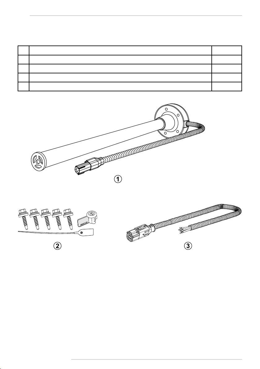
№Description Qty
1“TKLS” Fuel Level Sensor with Plastic Cover 1 pc.
2Mounting Kit* 1 set
3Signal Cable in Corrugated Pipe 7,5 m.
4Warranty Certicate 1 pc.
Scope of Supply
*The mounting kit includes following tools:
Seal gasket – 1 pc.
Self-tapping screws with mounted washer and sealing, M5 size – 5 pc.
Rivet nut, knurled, M5 size – 5 pc.
Machine screw, M5 size – 5 pc.
Plastic seal – 1 pc.
Meter seal (for connector) – 1 pc.
End cap (spare) – 1 pc.
Fuse with holder – 1 pc.
The gure given above shows just an example of the scope of supply which can dier from the real set delivered with the TKLS sensor.
TKLS • USER MANUAL 9
TechnoKom © 2014
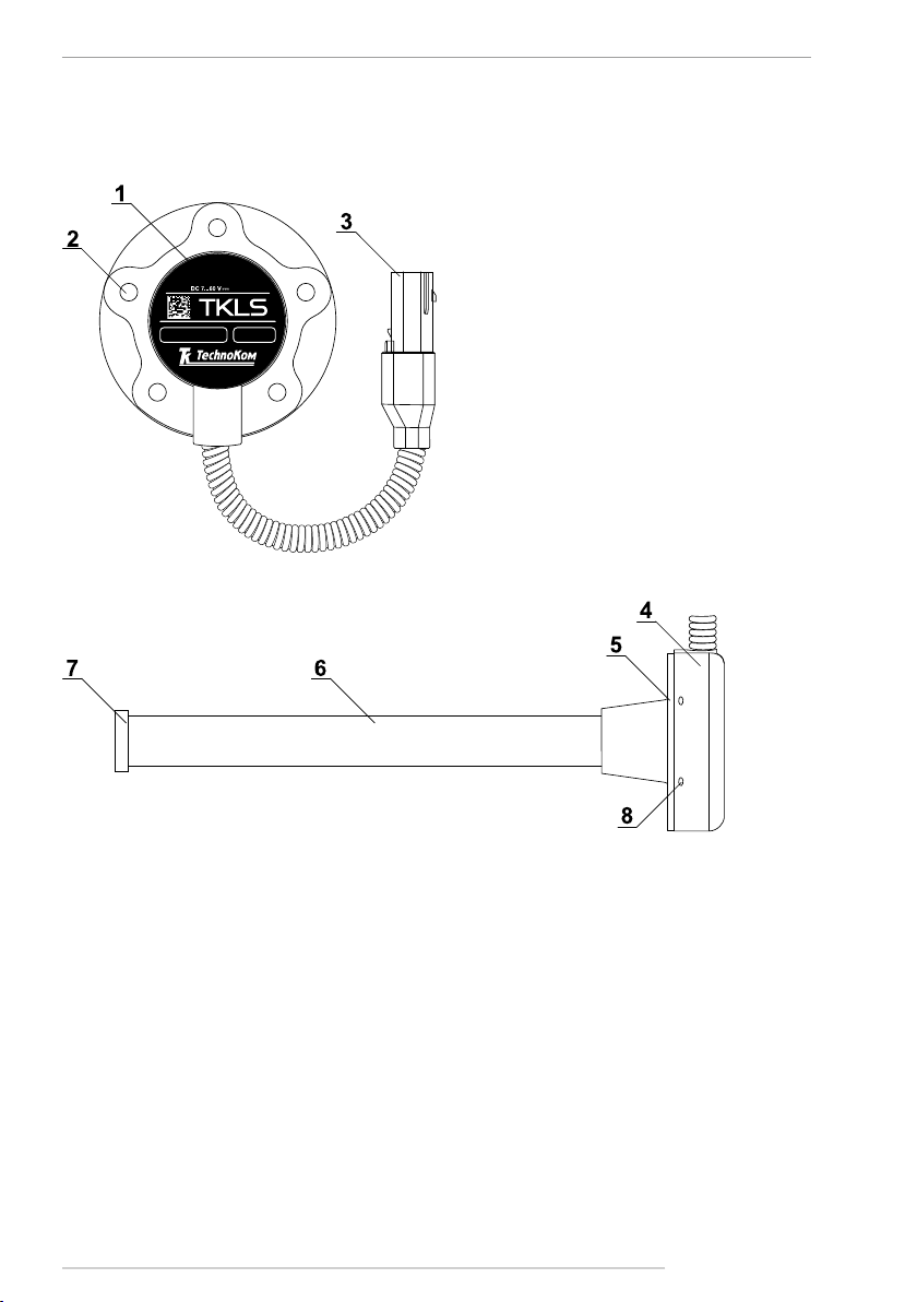
Components of Sensor
1. Product identication1.
2. Mounting hole (x5).
3. Interface Connector 1 (male).
4. Sensor cover.
5. Seal gasket.
6. Measuring probe.
7. End cap2.
8. Sealing hole (x4).
1 Device designation contains trademark and contact details of the manufacturer, device description, serial number and release date of the device.
2The sensor is supplied with a transport plug, which should be removed before sensor installation.
FUEL
LEVEL SENSOR
02/2015S/N 10003135
30 mA
www .tkls.eu

TKLS • USER MANUAL
10
TechnoKom © 2014
Interface Connectors
№Wire Colour Assignment
1Red +Vin
2Orange RS-485 (A)
3Gray Frequency output (ОК)
4Black -Vin
5Brown RS-485 (B)
6White Digital input (active low)
Interface Connector 1 (male)
View from side of pins
Connector 2 (female)
View from side of sockets. This is the connector of
the signal cable supplied with the sensor.
Both connectors are keyed to prevent wrong orientation.
TKLS • USER MANUAL 11
TechnoKom © 2014
Getting started
Before installation it is highly recommended to check the sensor for any mechanical damage.
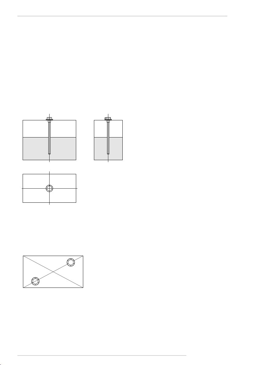
Select sensor installation area
• The sensor location depends on the geometric form of the tank and should be chosen in
such a way as to provide accurate readings regardless of fuel movement in the tank during
vehicle motion.
• Normally, the sensor should be located at the centre of the top of the tank. See gures
below:
• If it is impossible to install the sensor as shown above, it should be located as close as
possible to the recommended area.
• If, due to the geometric features of the tank, one fuel level sensor does not provide the
required accuracy of readings, it is recommended that several sensors are installed into the
tank. A set of two sensors is commonly used in this way. In this case, the fuel level in the tank
amounts to the average readings of the two sensors.
Prepare fuel tank for the sensor installation
All preparation work must be performed in accordance with the safety requirements specied
for the tank:
• Before installation on a petrol tank, it must be completely emptied of petrol and lled with
water.

TKLS • USER MANUAL
12
TechnoKom © 2014
• When cutting the sensor, be sure that the cut is straight and perpendicular to the roll axis
of the sensor.
• Before drilling, ensure that there aren’t any bafe plates inside in the tank in the proposed
sensor installation area within a radius of 20 mm. This can be checked by drilling a small hole
(about 3 mm) in the installation area.
• Drill a central hole 35…37 mm diameter using a bimetal boring bit.
• Drill ve holes for SAE-5 bolts.
• Install the seal gasket on the sensor, then mount the sensor into the tank.
Cut the sensor length
• The sensor length can be cut to match the specic fuel tank. To do this, you should follow
these steps:
• Measure the tank depth by inserting a ruler in the tank through the central hole that has
been prepared for installing the sensor.
• Measure the tank depth on the effective length of the sensor L. It is recommended that the
sensor is shorter than the tank depth by 10-30 mm to prevent false reading due to impurities
(including water) in the bottom of the tank. The effective length of the sensor should be
adjusted depending on the amount of the impurities.
TKLS • USER MANUAL 13
TechnoKom © 2014
The eective length of the sensor must be at least 150 mm after cutting.
i
NOTE
• After cutting, install the supplied end cap on the measuring probe (see gure below). Do
not forget to remove the transport plug before the sensor installation.
• After the end cap installation, it is highly recommended to set up the empty and full tanks
calibration readings. The calibration can be performed using the TKLS conguration tool.
Calibrate a range of sensor readings
The empty/full tank calibration is required to set a measuring range of the sensor.
It is highly recommended to start with an empty tank calibration and perform it before the
sensor rst use while the measuring probes have not been inserted in fuel yet. If the sensor
is used earlier, it must be removed from fuel tank and the measuring tubes must be cleaned
from fuel residues (e.g. let the fuel drain off the tubes for about 15-20 minutes after the sensor
removing from fuel tank).
To set an empty tank readings:
• connect the TKLS sensor to the conguration tool following the instruction given in the help
le for this software. The sensor readings of empty tank will be displayed on the Settings tab
of the conguration tool;
It is not recommended to disconnect the TKLS sensor from the conguration tool during the
calibration in order to prevent calibration data loss. If you need to save the calibration data,
press the Save settings on the conguration tool button before disconnecting the sensor
from PC.
i
NOTE
• wait for about 1-2 minutes and apply empty tank readings pressing the button in the
“Empty tank” eld. The sensor initial readings will be entered in the “Empty tank” eld;
• after setting the empty tank readings, you need to perform the full tank calibration.
TKLS • USER MANUAL
14
TechnoKom © 2014
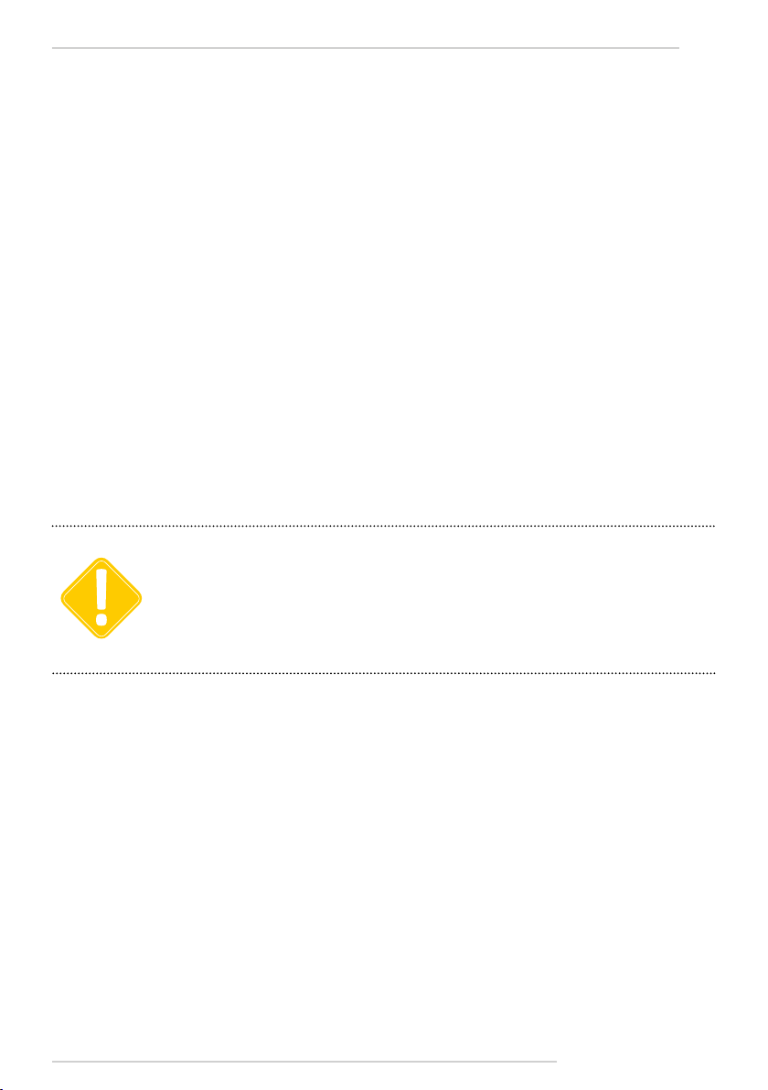
Install the sensor in tank
• Install the seal gasket on the sensor with the wide side of the seal’s outer ring facing the
sensor (see gure below). When installing the seal, also be sure that the mounting holes of
the sensor matches the mounting holes of the seal.
• Install the sensor into the tank and tighten ve fastening screws supplied with the sensor.
To set a full tank readings:
• connect the TKLS sensor to the conguration tool following the instruction given in the help
le for this application.
• if the sensor is calibrated by inserting into a fuel storage, rst turn the sensor upside down
and pour about 10-20 ml of fuel into the measuring probes through the drain hole, e.g. by
means of a syringe, or pour it into the measuring probes from above. Then install the sensor
in the storage lled up with fuel;
• if the sensor is calibrated by pouring fuel into the measuring probes, rst you need to turn
the sensor upside down, block the drain hole, then ll up the measuring probes with fuel;
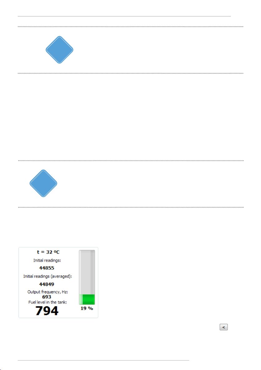
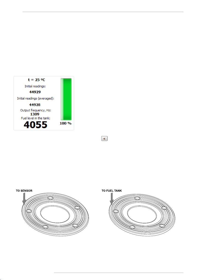
• the sensor readings will be displayed on the conguration tool:
• apply full tank readings pressing the button in the “Full tank” eld. The sensor initial
readings will be entered in the “Full tank” eld;
TKLS • USER MANUAL 15
TechnoKom © 2014
Sensor Connection
This section covers connection procedures of the TKLS fuel level sensor:
• Power supply connection
• RS-485 bus connection
• Frequency output connection
The sensor is supplied with a 7.5m signal cable in a corrugated pipe. The cable is equipped
with a female connector (Connector 2) for connecting to the sensor (to Connector 1). Both
connectors are keyed, which prevents incorrect orientation.
When making connections, pay careful attention to the safety rules stipulated by the
regulations for motor vehicle repair procedures. All connections should be properly isolated
and securely connected. If the wire is too short, it can be spliced with a wire of at least 0.5
mm2 cross section (20 AWG or thicker).
The TKLS sensor can be connected to any external unit that supports ModBus or LLS
protocols to transfer fuel level readings.
The TKLS sensor is equipped with a frequency output that provides transfer of fuel level
values in the form of pulses at a variable frequency. The sensor is also capable of measuring
ambient temperature.
IMPORTANT All connections should be performed when the sensor and all external devices be connected to the sensor
are disconnected from the power supply.
TKLS • USER MANUAL
16
TechnoKom © 2014
Power Supply Connection
When making the power connection, pay careful attention to the safety rules stipulated by the
regulations for motor vehicle repair procedures.
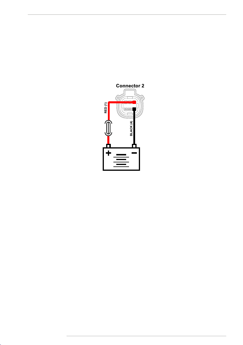
The sensor is supplied with a fuse intended to provide short circuit protection of the power
supply. The fuse holder is installed on a wire ring, which should be cut before operation.
The power supply input of the sensor is rated for a voltage of 7-60 V.
To connect the power to the sensor you should follow these steps:
• Connect “+Vin” wire of the signal cable to “+Vin” line of vehicle power system and connect
“-Vin” wire to “-Vin” line of the vehicle power system.
• Connect the fuse supplied with the sensor to the “+Vin” line. The fuse should be placed as
close as possible to the point where the TKLS is connected to vehicle power system.
• Connect Connector 2 of the signal cable to the male Connector 1.
TKLS • USER MANUAL 17
TechnoKom © 2014
RS-485 (TIA/EIA-485-A) Bus
Connection
The TKLS sensor is equipped with an RS-485 (TIA/EIA-485-A) bus, which allows the sensor
to transfer collected data to an external unit equipped with RS-485.
The TKLS supports following data transmission protocols: AGHIP, LLS and ModBus. The
data transfer protocol can be selected using the conguration program.
The TKLS sensor is able to transfer fuel level readings in liters, ADC stages or percent of
full tank via RS-485. To send fuel level readings in liters and %, the volume calibration table
must be recorded in the TKLS. This option, as well as the protocol, can be congured in the
conguration tool.
TKLS sensor can be connected to following devices via RS-485 bus:
• AutoGRAPH on-board vehicle tracking device. Communication can be provided in AGHIP,
LLS and Modbus protocols. When connecting to AutoGRAPH device equipped with two RS-
485 buses, TKLS-L must be connected to RS-485-1;
• any third-party device equipped with RS-485 bus and supporting LLS or Modbus protocol.
IMPORTANT
When connecting TKLS-L to RS-485 bus of an external device, be careful not to cross the “A” and “B”
wires, otherwise correct operation of the sensor is not guaranteed. Also ensure that TKLS-L sensor
and all external devices to be connected to the RS-485 bus are disconnected from the power supply.
i
NOTE The AGHIP format (AutoGRAPH Hardware Interface Protocol) is intended for communication with
AutoGRAPH on-board controllers and provides transmissions of additional information.
TKLS • USER MANUAL
18
TechnoKom © 2014
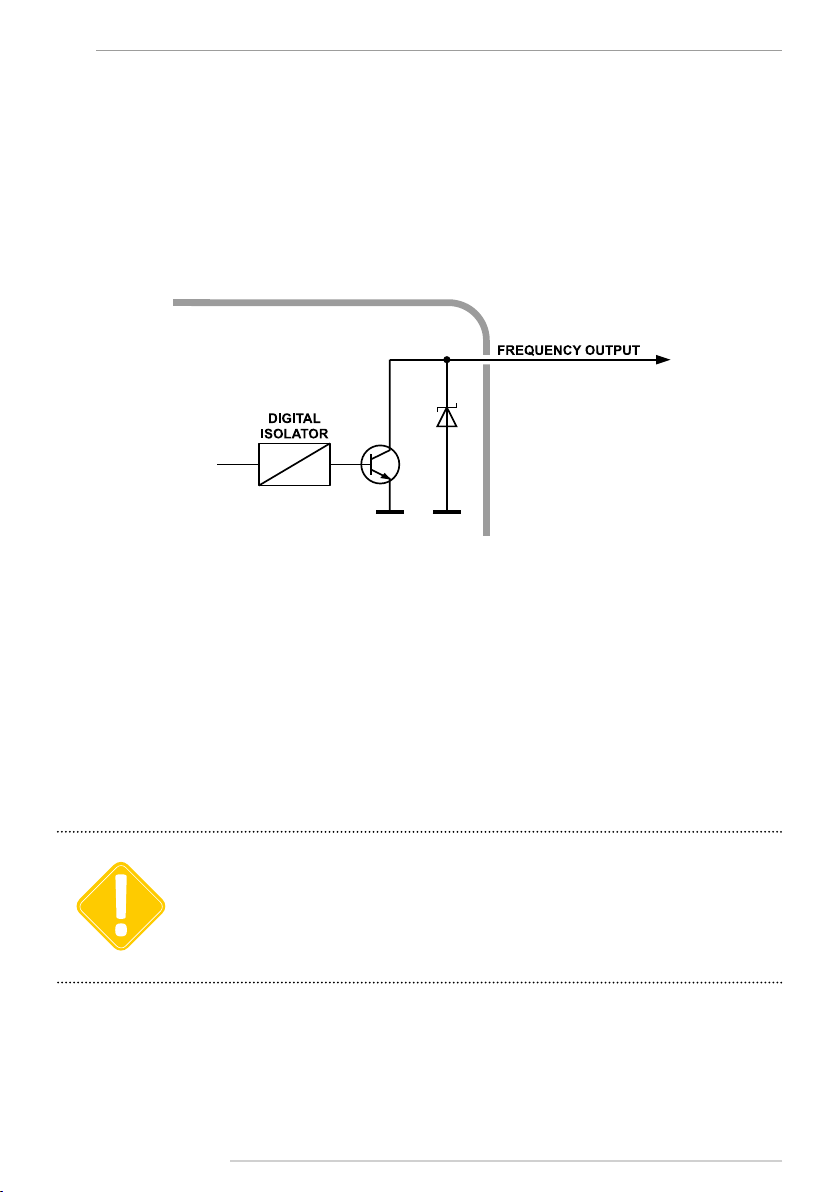
Frequency Output Connection
TKLS sensor is equipped with one frequency output, which is open-collector. The frequency
of the output signal is proportional to the fuel level in the tank.
The output frequency range varies from 100 Hz to 3000 Hz.
Maximum load current should not exceed 200 mA.
Internal diagram of frequency output:
IMPORTANT When connection to the AutoGRAPH controller, the sensor must be connected to one of the active low
digital inputs of the controller (inputs 1-4).
The frequency output is intended for connection:
• to the digital input of the AutoGRAPH on-board vehicle tracking device, which can acquire
the reading in frequency form;
• to digital input of a third-party device supporting frequency measuring within the range of
frequency signal provided by TKLS sensor.
When connection to the AutoGRAPH controller, the sensor must be connected to one of the
active low digital inputs of the controller (inputs 1-4).Before connecting to the TKLS-L, the
input of the AutoGRAPH must be switched to Frequency Mode.
The conguration of third-party device must be performed according to the instructions given
in the User Manual of that device.

TKLS • USER MANUAL 19
TechnoKom © 2014
Auto calibration
TKLS sensors with rmware of version TKLS-1.37 and higher support automatic calibration.
During the automatic calibration fuel is transferred from storage tank to fuel tank with the
calibrated sensor. The transferred fuel volume is measured by a owmeter which output is
connected to digital input of the TKLS sensor. At each calibration step, when the required
fuel volume has been transferred in the tank, the sensor waits until the fuel uctuations in
the tanks stop and takes measurements with the specied timeout. If difference between
adjacent readings does not exceed the acceptable deviation, the last reading is added in the
calibration table – in the form of ADC stages and frequency, along with actual fuel level in the
tank, calculated using the owmeter readings.
The TKLS sensor is connected to a PC via USB-RS485 Converter produced by TechnoKom.
For more detailed information see section “Sensor conguration” of this User Manual.
Structural diagram of auto calibration station:
Described below is the instruction on the TKLS sensor auto calibration procedure:
• Connect the sensor which is being
calibrated to the TKLS conguration tool;
• Go to the “Settings” tab and set the sensor
frequency output to the Auto calibration
mode (Fig.1);
Fig.1. Frequency output conguration for auto calibration mode.
TKLS • USER MANUAL
20
TechnoKom © 2014
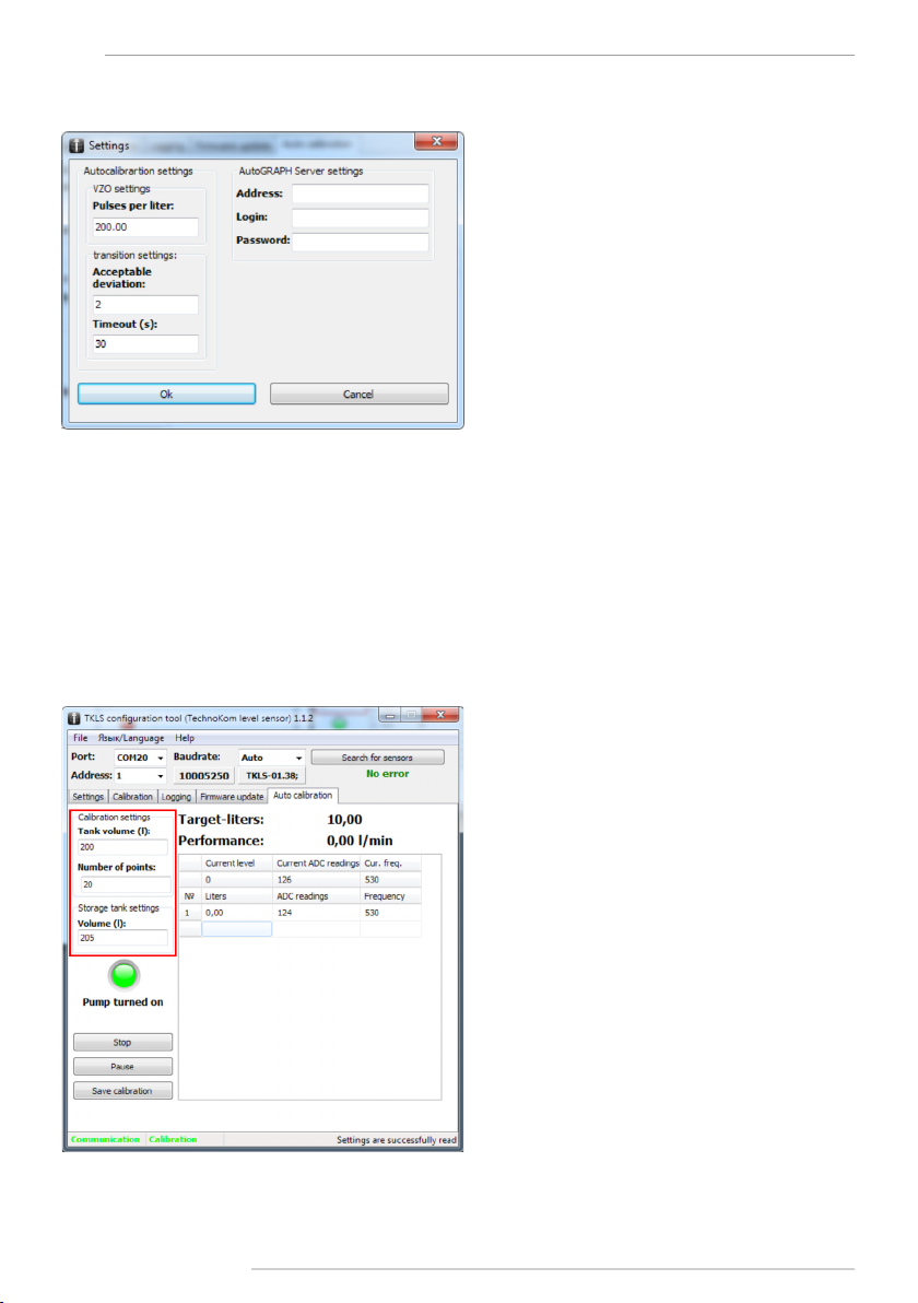
• Then select Menu File – Settings... in the conguration tool;
Fig.2. Calibration settings.
• In the Settings menu (Fig.2), set up the owmeter parameters – a number of pulses
accounted for 1 litre of fuel. This characteristic is given in technical documentation on the
owmeter;
• Also set up acceptable deviation and timeout between sensor adjacent readings;
• Then apply settings by pressing OK button and go to the Auto calibration tab;
• Before starting the calibration, specify the fuel tank volume in the “Tank volume (l)” eld
(Fig.3). Also specify a number of calibration points in the “Number of points” eld. Maximum
value is 50;
• Then specify the storage tank volume in litres (Fig.3);
Fig.3.Auto calibration tab.
Table of contents
Popular Automobile Accessories manuals by other brands


Monster
Monster iCar PowerPlug Dual USB 700 user guide

Aries
Aries 2169000 installation manual

Herd
Herd KW01 installation guide

Whelen Engineering Company
Whelen Engineering Company UNECE Mini Justice installation guide

Mishimoto
Mishimoto MMRAD-NEO-01 install guide

Saris
Saris BONES 3 801 Assembly instructions


