Autel MaxiCharger DC Fast User manual


i
Trademarks
Autel
®
and MaxiCharger
®
are trademarks of Autel Intelligent Technology Corp., Ltd.,
registered in China, the United tates and other countries. All other marks are
trademarks or registered trademarks of their respective holders.
Copyright Information
No part of this manual may be reproduced, stored in a retrieval system or transmitted, in
any form or by any means, electronic, mechanical, photocopying, recording, or otherwise
without the prior written permission of Autel.
Disclaimer of Warranties and Limitation of Liabilities
All information, specifications and illustrations in this manual are based on the latest
information available at the time of printing.
Autel reserves the right to make changes at any time without notice. While information of
this manual has been carefully checked for accuracy, no guarantee is given for the
completeness and correctness of the contents, including but not limited to the product
specifications, functions, and illustrations.
Autel will not be liable for any direct, special, incidental, indirect damages or any
economic consequential damages (including the loss of profits).
IMPORTA T
Before operating or maintaining this unit, please read this manual carefully, paying extra
attention to the safety warnings and precautions.
For Services and Support:
Web: www.autelenergy.com
Tel: +49 (0) 89 540299608 (Europe)
0086-755-2267-2493 (China)
Email: [email protected]
For technical assistance in all other markets, please contact your local selling agent.

ii
CO TE TS
USI G THIS MA UAL ..................................................................................................... 1
CONVENTION ................................................................................................................... 1
Bold Text ................................................................................................................ 1
Notes ...................................................................................................................... 1
Hyperlinks .............................................................................................................. 1
Procedures ............................................................................................................. 2
TERMINOLOGY ................................................................................................................... 3
SAFETY ............................................................................................................................ 4
AFETY WARNING ............................................................................................................ 4
OWNER RE PON IBILITIE .................................................................................................. 4
IN TALLATION ENGINEER QUALIFICATION ........................................................................... 5
UAGE IN TRUCTION ........................................................................................................ 5
YMBOL ON THE MAXICHARGER ........................................................................................ 5
DI PO AL IN TRUCTION ................................................................................................... 6
CYBER ECURITY .............................................................................................................. 6
GE ERAL I TRODUCTIO ............................................................................................ 7
PRODUCT OVERVIEW ......................................................................................................... 8
WORKING PRINCIPLE DIAGRAM ......................................................................................... 12
LOCAL ERVICE PORTAL .................................................................................................. 13
CLOUD ERVICE PORTAL ................................................................................................. 14
PREPARATIO .............................................................................................................. 15
BEFORE IN TALLING......................................................................................................... 15
UNPACKING ..................................................................................................................... 16
MOVING THE CABINET TO THE ITE .................................................................................... 17
Hoisting the Cabinet ............................................................................................. 17
Forkli ting the Cabinet .......................................................................................... 18
PACKING LI T .................................................................................................................. 19

iii
IN TALLATION TOOL ....................................................................................................... 21
I STALLATIO .............................................................................................................. 22
PREPARING THE IN TALLATION ITE .................................................................................. 23
Location Requirements ........................................................................................ 24
Preparing the Foundation ..................................................................................... 27
IN TALLING THE CABINET.................................................................................................. 32
PREPARING FOR ELECTRICAL CABLE IN TALLATION ............................................................ 35
ELECTRICAL WIRING ........................................................................................................ 36
Connecting the PE Wire ....................................................................................... 36
Connecting the Enclosure to the earth ................................................................. 37
Connecting the AC Input Wires ............................................................................ 38
Connecting the Ethernet Cable ............................................................................ 39
Installing SIM Card ............................................................................................... 40
IN TALLING THE CHARGING MODULE ............................................................................... 41
IN TALLING THE EXTERNAL RE IDUAL-CURRENT DEVICE ..................................................... 44
PREPARING FOR COMMI IONING ...................................................................................... 44
OPERATIO ................................................................................................................... 45
BEFORE UE ................................................................................................................... 45
EMERGENCY TOP .......................................................................................................... 46
CHARGING PROCEDURE ................................................................................................... 47
Screen Layout ...................................................................................................... 47
Authorization ........................................................................................................ 48
Start Charging ...................................................................................................... 49
Charging............................................................................................................... 50
Stop Charging ...................................................................................................... 51
Finish Charging .................................................................................................... 51
CHARGING ERROR ......................................................................................................... 52
Connector Connection Error................................................................................. 52
iv
Authorization Failure ............................................................................................ 52
Charging Start Failure .......................................................................................... 52
Charging Failure ................................................................................................... 52
ENERGIZING THE MAXICHARGER ....................................................................................... 52
DE-ENERGIZING THE MAXICHARGER .................................................................................. 53
Measuring the AC Voltage ................................................................................... 53
Measuring the DC Voltage ................................................................................... 54
REMOVING CONDEN ATION .............................................................................................. 55
LOCAL ERVICE PORTAL OPERATION ............................................................................... 56
Setting the OCPP Parameters ............................................................................. 56
MAI TE A CE .............................................................................................................. 57
ROUTINE MAINTENANCE ................................................................................................... 57
Residual Current Device Maintenance ................................................................. 57
Cleaning the Cabinet ............................................................................................ 58
Cleaning and Replacing the Air Filters ................................................................. 58
IN PECTION AND MAINTENANCE ........................................................................................ 61
REMOTE MAINTENANCE .................................................................................................... 61
MAINTENANCE CHEDULE ................................................................................................ 62
TROUBLESHOOTI G A D SERVICE ........................................................................... 63
TROUBLE HOOTING ......................................................................................................... 63
ERVICE ......................................................................................................................... 65
TECH ICAL SPECIFICATIO S ..................................................................................... 66
GENERAL PECIFICATION ............................................................................................... 66
PACKAGING PECIFICATION ............................................................................................ 68
IN TALLATION PECIFICATION ......................................................................................... 69
COMMUNICATION INTERFACE PECIFICATION .................................................................... 71
POWER RATING PECIFICATION ...................................................................................... 72
AC INPUT AND DC OUTPUT PECIFICATION ...................................................................... 73

v
POWER CON UMPTION PECIFICATION ............................................................................ 75
INPUT HORT CIRCUIT CURRENT PECIFICATION .............................................................. 76

1
Using This Manual
This manual contains device usage instructions.
ome illustrations shown in this manual may contain modules and optional equipment
that are not included in your system. Contact your sales representative for availability of
other modules and optional tools or accessories.
The document is intended for these groups:
Owner of the MaxiCharger (see Owner Responsibilities)
Installation engineer (see Installation Engineer Quali ications)
Conventions
Bold Text
Bold text is used to highlight selectable items such as buttons and menu options.
Example:
Tap OK.
otes
OTE: provides helpful information such as additional explanations, tips, and
comments.
IMPORTA T: indicates a situation that, if not avoided, may result in damage to the
test equipment or vehicle.
DA GER: indicates an imminently hazardous situation which, if not avoided, will
result in death or serious injury to the operator or bystanders.
WAR I G: indicates a potentially hazardous situation which, if not avoided, could
result in death or serious injury to the operator or to bystanders.
CAUTIO : indicates that disobeying the instruction can cause damage to the
equipment or property.
Hyperlinks
Hyperlinks are available in electronic documents. Blue italic text indicates a selectable
hyperlink and blue underlined text indicates a website link or an email address link.

2
Procedures
An arrow icon indicates a procedure. For example:
To reset the MaxiCharger
Ensure that the situation is safe again.
Turn the Emergency Stop button clockwise to release it.
The MaxiCharger will start and the error message will disappear from the
touchscreen.
The MaxiCharger will resume the normal operation.

3
Terminology
Table 1-1 Terminology
Term Definition
AC Alternating current
CCS Combined Charging ystem; a standard charging method for
electric vehicles
CCU Charging Control Unit; a control unit used to communicate with
BM , and control the power delivery to the EV
CHAdeMO Abbreviation of CHArge de Move; a standard charging
method for electric vehicles
DC Direct current
ECU
Equipment Control Unit; a control unit used to handle the
system protection and the charging module control and
distribution
EV Electric vehicle
OCPP Open charge point protocol; open standard for communication
with charge stations
PE Protective earth (ground)
RCBO Residual current breaker with overload
RCD Residual current device; a device that breaks an electrical
circuit when it detects a current leakage
RFID Radio-frequency identification; a method of charging
authentication
SoC tate of charge; the level of charge of an electric battery relative
to its capacity. 0%=empty; 100%=full
SPD urge protection device; a device intended to protect electrical
devices from voltage spikes in AC circuits
TCU
Transaction Control Unit; intelligent hardware to handle the
human-machine interface, metering, transaction, and
communication with back office

4
Safety
Safety Warnings
Disconnect the power supply to the MaxiCharger during the entire installation
procedure.
The load capacity of the grid must meet the requirements of the MaxiCharger.
Connect the MaxiCharger to a grounded, metal, permanent wiring system.
Otherwise, use the equipment-grounding conductor with the circuit conductors and
connect it to the equipment grounding terminal or lead on the product.
Unqualified personnel must keep a safe distance during the entire installation
procedure.
The connections to the MaxiCharger must comply with all applicable local rules.
Only use electrical wires of sufficient gauge and insulation to handle the rated
current and voltage demand.
Protect the wiring inside the MaxiCharger from damage and do not obstruct the
wiring when you perform maintenance on the cabinet.
Keep the cabinet away from all water source.
Protect the MaxiCharger with safety devices and measures as specified by local
rules.
Wear proper personal protective equipment such as protective clothing, safety
gloves, safety shoes, and safety glasses when necessary.
Owner Responsibilities
The MaxiCharger owner runs the MaxiCharger for commercial or business purposes for
itself or third-party usage. To protect the user, other employees, or third parties, the owner
bears legal responsibility for the operation of the charger and has the following
responsibilities:
Identify any hazards (in terms of a risk assessment) resulting from the working
conditions on the site.
Know and implement all local rules.
Install protective devices before operating the MaxiCharger.
Make sure all protective devices are installed after installation or maintenance work.
Prepare an emergency plan that instructs people what to do in case of an
emergency.

5
Make sure that all employees and third parties are qualified in accordance with the
applicable local rules to perform their work.
Make sure that there is sufficient space around the MaxiCharger to safely do
maintenance and installation work.
Identify a site operator who is responsible for the safe operation of the MaxiCharger
and for the coordination of all work, if the owner does not do these tasks.
Make sure that all qualified installation engineers obey local rules and installation
instructions, and adhere to the specifications of the MaxiCharger.
Installation Engineer Qualifications
The installation engineers must:
Be qualified in accordance with all applicable local rules to do the work.
Be completely familiar with the MaxiCharger and its safe installation.
Obey all local rules and the instructions in the installation manual.
Usage Instructions
Do not use the MaxiCharger and immediately contact the manufacturer if any of the
following situations occur:
Damaged enclosure
Damaged EV charging cable or connector
Expose to lightning
Expose to water
Expose to nature disaster, fire or smoke
Symbols on the MaxiCharger
Table 2-1 Symbol Description
Symbol Risk Description
General risk
Hazardous voltage with risk of electrocution

6
Symbol Risk Description
Waste from electrical and electronic equipment
Hot surface with risk of burn injuries
Disposal Instructions
To avoid negative effect on the environment and human health due to potential
hazardous substances, dispose of parts according to local laws and guidance. Proper
disposal of this product will allow for the reuse the materials and protect the environment.
Cyber Security
OTE
This section applies only to the Ethernet and Wi-Fi connections.
The MaxiCharger can use a network interface for connection and information and data
communication. The owner bears the responsibility of providing a secure connection
between the MaxiCharger and the owner’s network or any other networks.
Appropriate measures shall be taken by the owner to shield the MaxiCharger, the network,
the system, and the interface from any security breaches, unauthorized access,
interference, intrusion, leakage and/or theft of data or information. These measures may
include firewalls, authentication methods, data encryption, anti-virus programs, etc.
Autel is not liable for damages and/or losses resulting from security breaches.

7
General Introduction
The Autel MaxiCharger is designed to charge an electric vehicle (hereinafter called EV).
Our chargers provide you with safe, reliable, fast, and smart charging solutions.
The MaxiCharger is intended for the DC charging of EVs and is intended for both indoor
and outdoor use in fleets, highway rest stops, commercial parking garages, and other
locations.
DA GER
If you use the MaxiCharger in any way other than described in its documentation,
you can cause death, injury, and property damage.
Use the MaxiCharger only as intended.
OTE
The images and illustrations depicted in this manual may differ slightly from the actual
product.
This manual will instruct you how to install and operate the MaxiCharger.

8
Product Overview
1. Main Cabinet
2. Eye Bolt — for equipment movement, loading and unloading
Figure 3-1 MaxiCharger Overvie , Outside

9
3. tatus Indicator — displays the current status of the MaxiCharger
4. Light ensor
5. Tempered Glass — protects indicator and touchscreen, etc.
6. Touchscreen (the size of the touchscreen is optional)
7. RFID Card Reader
8. Point of ale (PO ) Terminal (the shape might varies depending on the terminal
you choose)
9. Holster
10. Loudspeaker
11. ocket (optional)
12. Front Cabinet Door
13. Front/Rear Base Cover — you can move the device using a forklift after removing
the cover
14. Antenna
15. Waterproof Cable Fixing Connector — for the extended charging cable
16. Emergency top Button
17. Vent
18. Handle Lock
19. Connector
20. Base
OTE
Autel can deliver the MaxiCharger with different payment terminals. The available options
vary depending on the region and country where the MaxiCharger is installed. If you need
more information about different options for the payment terminals, consult Autel
customer support.

10
Table 3-1 Status Indicator Key
Charging Status Color Meaning
Standby Mode olid Green The connector is available.
EV Connected olid White An EV is connected to the
MaxiCharger.
Charging Illuminating Green in
Turn
Indicates how much of your EV is
charged.
Charge Complete
Flashing Green An EV is fully charged or has
stopped charging.
Reservation Flashing White The MaxiCharger is reserved.
Error olid Red An error has occurred.

11
A. Main Breaker — connects/disconnects the charging module
B. AC Filter (optional)
Figure 3-2 MaxiCharger Overvie , Inside

12
C. PD Breaker
D. PD
E. Auxiliary AC Main Fuse
F. Auxiliary RCCB
G. Cable Gland Plate
H. Charging Module
I. Heater Circuit Fuse
J. Contactor Circuit Fuse
K. 48V Auxiliary AC Fuse
L. 24V Auxiliary AC Fuse
M. PE Busbar — connects the PE cable
Working Principle Diagram
Figure 3-3 Working Principle Vie
OTE
Fuse 1 is used when the power rate of the MaxiCharger exceeds 120 kW.
The number of used power modules varies according to the power rate of the
MaxiCharger.

13
Local Service Portal
The Local ervice Portal provides information about the MaxiCharger, allows for the
configuration of the key parameters during commissioning, and enables diagnostics on
site. For detailed operation procedures, see Local Service Portal Operations.
Table 3-2 Parameter Description
Parameter Example (* indicates variables)
Charger ID DG1120B1**********
OCPP IP *******.*******.**
OCPP-URL address **********
Port number ***
OCPP encryption
method ***
Country code UK
etwork selection auto/wifi/4g
Supplier Autel
Control board S C06G120********
MAC address ba:9f:aa:8c:**:**
Password 000000
Connection ID 0: Connectors 1 and 2 initialization
Charger configuration
model 120:120kW
MGR IP *******.*******.**
MGR URL **********
MGR PORT ***
MGR SEC https

14
Parameter Example (* indicates variables)
MGR E ABLE 1: Enable
http API address temporarily useless
Running environment
1: China /3: Europe /4: UK /5: U A
Payment method
1: QR code 2: NFC module 3: QR code and NFC module
4: Credit card 5: QR code and credit card 6: NFC module
and credit card 7: All
Http test switch 1: Production environment
Device Model Maxi CN DC**********
Rated Power 120kW
Rated Voltage 1000V
Maximum current 200A
Set Current 200A
Max Power 120kW
Cloud Service Portal
Autel provides a set of cloud-based tools to commission, monitor, and troubleshoot the
MaxiCharger. For more information, contact your Autel e-Mobility representative.
Table of contents
Other Autel Automobile Accessories manuals

Autel
Autel MaxiVCI V150 User manual

Autel
Autel Maxi US AC W12-H User manual

Autel
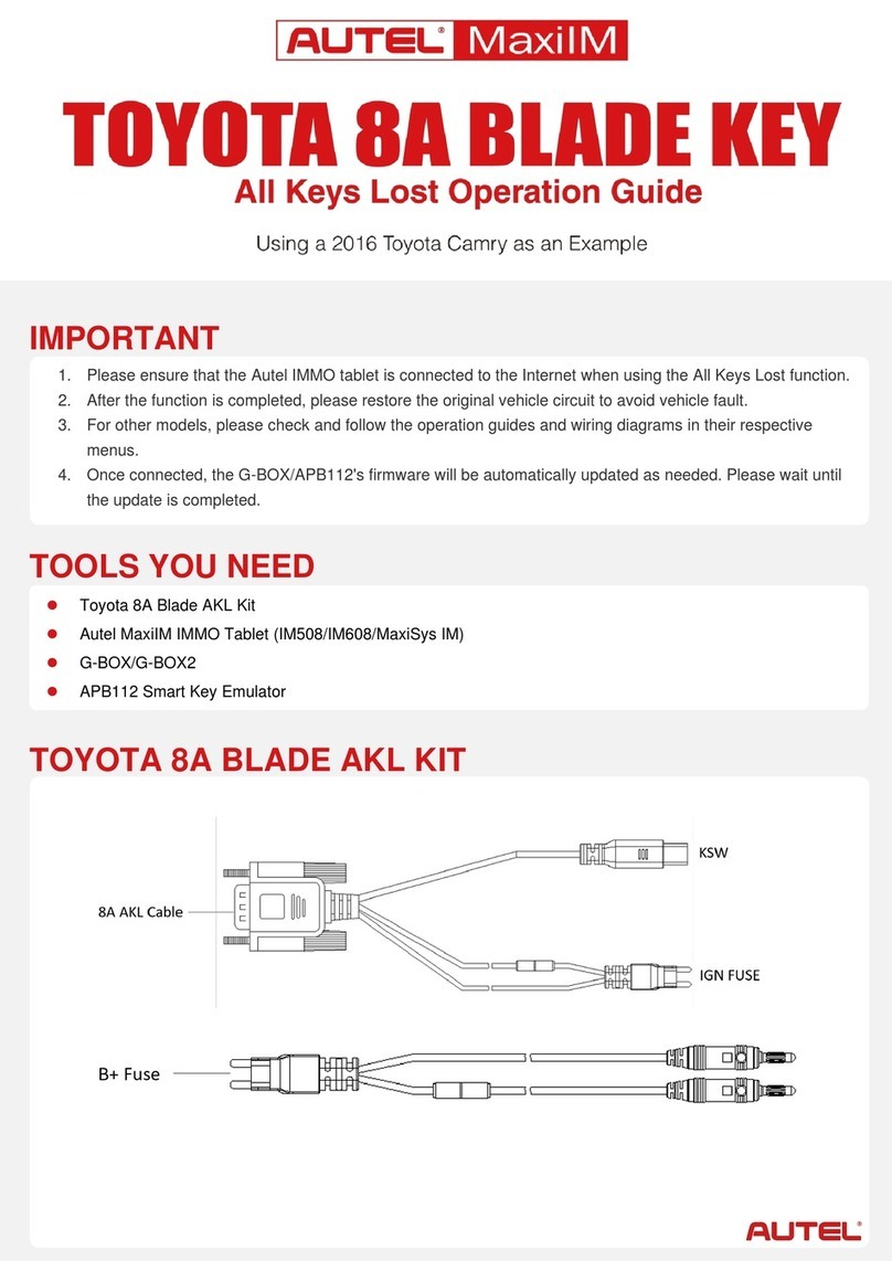
Autel MaxiIM TOYOTA 8A BLADE KEY User manual

Autel
Autel MaxiCharger AC Wallbox Home User manual

Autel
Autel ATS100 User manual

Autel
Autel MaxiTPMS TS508 User manual

Autel
Autel APB112 User manual

Autel
Autel MaxiIM TOYOTA 8A BLADE KEY User manual
Popular Automobile Accessories manuals by other brands

Metra Electronics
Metra Electronics 99-7875 installation instructions

MTM
MTM MTM750 installation guide

Medifab
Medifab Houdini 28 quick start guide

Directed
Directed Directechs DB3 installation guide

Thule
Thule 1172 RAPID SYSTEM Fitting instructions

ECS Electronics
ECS Electronics HY-050-DH Fitting instructions electric wiring