Tecnam P2010 Technical specifications

AFMS N°D01 FOR GARMIN GFC700 AUTOPILOT INSTALLATION AND
RNAV/RNP NAVIGATION ELIGIBILITY
Page 1A-20
Section 1 –General
AUTOPILOT DESCRIPTION
Ed. 1, Rev. 0
Autopilot control panel
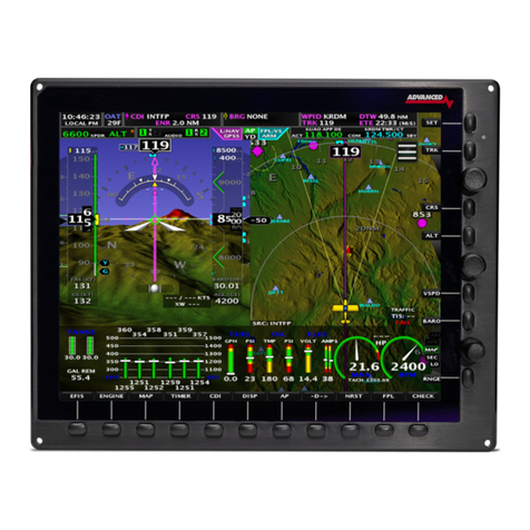
The GDU1044 includes a set of additional softkeys dedicated to the control of
Autopilot system.
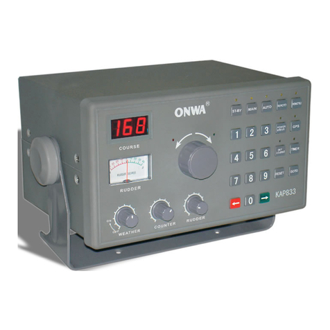
The following dedicated AFCS keys are located on the bezel of the MFD (refer
picture below):
1) AP Key: Engages/ disengages the autopilot
2) FD Key: Activates/deactivates the flight director only
3) NAV Key: Selects/deselects Navigation Mode
4) ALT Key: Selects/deselects Altitude Hold Mode
5) VS Key: Selects/deselects Vertical Speed Mode
6) FLC Key: Selects/deselects Flight Level Change Mode
7) HDG Key: Selects/deselects Heading Select Mode
8) APR Key: Selects/deselects Approach Mode
9) VNV Key: Selects/deselects Vertical Path Tracking Mode for Vertical
Navigation flight control
10) NOSE UP/ NOSE DN Keys: Control the mode reference in Pitch Hold,
Vertical Speed and Flight Level Change modes
Autopilot control panel

AFMS N°D01 FOR GARMIN GFC700 AUTOPILOT INSTALLATION AND
RNAV/RNP NAVIGATION ELIGIBILITY
Page 1A-21
Section 1 –General
AUTOPILOT DESCRIPTION
Ed. 1, Rev. 0
12.2 PILOT CONTROL WHEEL AND THROTTLE BUTTONS
On the left side of pilot‘s and copilot‘s control wheels there are two PTT switches
(the one on pilot control wheel is shown below as (1)) that, when pushed, allow
radio transmission. These switches are momentaneous ones thus acting in such a
way that when they are released the active COM device returns to the non-
transmitting state. These switches are already installed in the basic aircraft which
is not equipped with the autopilot.
The following additional dedicated AFCS controls are located on the pilot control
wheel, separately from the MFD, and on the throttle handle:
AP DISC Switch:
Disengages the autopilot and interrupts pitch trim operation
This switch may be used to mute the aural autopilot disconnect
alert.
AP Trim Switch:
Used to command manual electric trim. This composite switch
is split into left and right sides. The left switch is the ARM
contact and the right switch controls the DN (forward) and UP
(rearward) contacts. The AP TRIM ARM switch can be used to
disengage the autopilot and to acknowledge an autopilot dis-
connect alert and mute the associated aural tone. Manual trim
commands are generated only when both sides of the switch
are operated simultaneously. If either side of the switch is ac-
tive separately for more than three seconds, MET function is
disabled and ‗PTRM‘ is displayed as the AFCS Status Annun-
ciation on the PFD. The function remains disabled until both
sides of the switch are inactivated.
CWS Button:
While pressed, the Control Wheel Steering allows manual con-
trol of the aircraft while the autopilot is engaged and synchro-
nizes the flight director‘s Command Bars with the current air-
craft pitch (if not in Glideslope Mode) and roll (if in Roll Hold
Mode). Upon release of the CWS Button, the flight director
may establish new reference points, depending on the current
pitch and roll modes. CWS operation details are discussed in
the flight director modes section.
TO/GA Switch:
The GA Switch is located on the throttle handle.
Go Around and Takeoff modes are coupled pitch and roll
modes and are annunciated as both the vertical and lateral
modes when active. In these modes, the flight director
commands a constant set pitch attitude and keeps the
wings level. The GA Switch is used to select both modes.
The mode entered by the flight director depends on wheth-
er the aircraft is on the ground.

AFMS N°D01 FOR GARMIN GFC700 AUTOPILOT INSTALLATION AND
RNAV/RNP NAVIGATION ELIGIBILITY
Page 1A-22
Section 1 –General
AUTOPILOT DESCRIPTION
Ed. 1, Rev. 0
The above mentioned AFCS controls are depicted in the below figures.
where:
1) PTT switch
2) AP DISC Switch
3) AP Trim Switch
4) CWS Button

AFMS N°D01 FOR GARMIN GFC700 AUTOPILOT INSTALLATION AND
RNAV/RNP NAVIGATION ELIGIBILITY
Page 1A-23
Section 1 –General
AUTOPILOT DESCRIPTION
Ed. 1, Rev. 0

AFMS N°D01 FOR GARMIN GFC700 AUTOPILOT INSTALLATION AND
RNAV/RNP NAVIGATION ELIGIBILITY
Page 1A-24
Section 1 –General
AUTOPILOT FUNCTIONS
Ed. 1, Rev.0
AUTOPILOT FUNCTIONS AND FEATURES13
GFC 700 autopilot suite is deeply integrated with Garmin G1000 avionics suite
which integrates both the a/p controls and the sensors providing the required data
to the servos.
The GFC 700 AFCS is equipped with the following main operating functions:
Flight Director (FD) — Flight director commands are displayed on the PFD. The
flight director provides:
Command Bars showing pitch/roll guidance
Pitch/roll mode selection and processing
Autopilot communication
Autopilot (AP) — Autopilot operation occurs within the pitch, roll, and pitch
trim servo and provides servo monitoring and automatic flight control in response
to flight director steering commands, AHRS attitude and rate information, and air-
speed.
Manual Electric Trim (MET) — The pitch trim servo provides manual electric
trim capability when the autopilot is not engaged.
ESP (Electronic Stability & Protection) keeps the aircraft within well defined op-
erational limits thus preventing the pilot to operate the aircraft outside a specific
envelope when it is being hand flown. This feature only operates when autopilot
is not engaged and its operation is mutually exclusive with autopilot operation.
USP (Underspeed Protection) is a flight director function that reacts to under-
speed conditions in a way that allows the autopilot to remain engaged but prevents
the airplane from stalling.

AFMS N°D01 FOR GARMIN GFC700 AUTOPILOT INSTALLATION AND
RNAV/RNP NAVIGATION ELIGIBILITY
Page 1A-25
Section 1 –General
AUTOPILOT FUNCTIONS
Ed. 1, Rev.0
13.1 ESP
Garmin GFC 700 is equipped with an envelope protection feature referred as ESP
(Electronic Stability & Protection). Electronic Stability and Protection continu-
ously monitors the aircraft. The system works by applying a correcting force to
the controls in order to nudge pilot to avoid extreme attitudes that may bring the
aircraft, if not corrected, to exceed normal flying envelope.
This software feature aims to provide protection against aircraft operation outside
a desired flight envelope. ESP will maintain the desired operating envelope, de-
fined at autopilot development time, by automatically engaging one or more ser-
vos when the aircraft is near the operating limit and nudging pilot to come back to
nominal operating envelope. While ESP utilizes the same sensors, processors, and
actuators as the GFC 700 autopilot, it is basically a separate function. ESP can be
overpowered by the pilot and can be temporarily disabled using the AP disconnect
or CWS switches. It functions independently of the aircraft‘s autopilot system
(although it uses the same control servos), so it basically operates ―in back-
ground‖ whenever the pilot is hand-flying the airplane.
The ESP feature will only function with GPS available, A/P MASTER
SWITCH ON (but autopilot not engaged) and aircraft above 200ft AGL.
ESP enabling:
As a standard, ESP will automatically set to enable at power-up.
The system is configured in order to allow the pilot to disable ESP (or re-enable it
if previously disabled after power up) via the AUX – SYSTEM SETTINGS page
on MFD.
If ESP has been disabled via MFD, it will automatically be set to ON upon any
battery/power reset.
ESP function uses the same servos that provide autopilot functionality while auto-
pilot is not engaged, as such, if power is cut from these servos both autopilot and
ESP functions will be unavailable.
Based on the above if ―AUTOPILOT MASTER‖ is set to OFF, power to servos is
cut irrespectively of their mode of operation (autopilot or ESP).
The pilot can interrupt ESP by pressing and holding either the Control Wheel
Steering (CWS) or Autopilot Disconnect (AP DISC TRIM INTRPT) switch. Up-
on releasing the CWS or AP DISC TRIM INTRPT switch, ESP force will again
be applied, provided aircraft attitude and/or airspeed are within their respective
engagement limits.
ESP can be enabled or disabled on the AUX-SYSTEM SETUP 2 Page on the
MFD.
AFMS N°D01 FOR GARMIN GFC700 AUTOPILOT INSTALLATION AND
RNAV/RNP NAVIGATION ELIGIBILITY
Page 1A-26
Section 1 –General
AUTOPILOT FUNCTIONS
Ed. 1, Rev.0
To enable or disable ESP:
1) Turn the large FMS Knob to select the AUX Page Group.
2) Turn the small FMS Knob to select the System Setup Page.
3) If necessary, select the SETUP 2 Softkey to display the AUX-SYSTEM
SETUP 2 Page.If the AUX-SYSTEM SETUP 2 is already displayed, pro-
ceed to step 4.
4) Press the FMS Knob to activate the cursor.
5) Turn the large FMS Knob to place cursor in the STABILITY & PRO-
TECTION field.
6) Turn the small FMS Knob to select ‗ENABLE‘ or ‗DISABLE‘.
7) Press the FMS Knob to remove the cursor.
ESP engagement and operation:
ESP is automatically enabled on system power up.
ESP unavailability and/or failure is indicated to the pilot on PFD by
the advisory “ESP not available” on alert window.
ESP will turn OFF upon loss of both GPS. The ADVSY “ESP OFF”
will appear on the alert window in case of loss of both GPS.
13.1.1 PITCH MODE
Pitch attitude boundaries are set based on P2010 aircraft performances. Since
pitch ESP augments the natural aircraft longitudinal stability, no special simbolo-
gy is required.
Value that have been set-up for the P2010 are as follows:
Nose above the horizon:
Engagement low threshold: + 15°
Engagement upper threshold: + 18°
Lower disengage threshold: + 12°
Nose below the horizon:
Engagement low threshold: -15°
Engagement upper threshold: -20°
Lower disengage threshold: -13°
ESP utilizes electronic torque and speed commands to augment the aircraft‘s sta-
bility: it uses an Electronic Torque Limit (ETL) and an Electronic Speed Limit
(ESL) to limit the maximum authority of the ESP function. ESP is inactive when
the pitch attitude is within the positive and negative engagement limits defined in
the certification gain file.
NOTE
NOTE

AFMS N°D01 FOR GARMIN GFC700 AUTOPILOT INSTALLATION AND
RNAV/RNP NAVIGATION ELIGIBILITY
Page 1A-27
Section 1 –General
AUTOPILOT FUNCTIONS
Ed. 1, Rev.0
When the aircraft reaches the engagement limit, ESP ramps up the servo torque
command to adjust the aircraft back toward zero pitch attitude. ESP uses a rate
command to drive the attitude back to the nominal range and does not try to con-
trol to a specific attitude. As the pitch attitude returns to the nominal range, the
torque and pitch rate are reduced until the aircraft reaches the disengagement limit
at which time ESP turns off. The disengagement threshold is sized so that the
transition from ESP being active to being inactive is transparent to the pilot (no
transient when ESP turns off).
If, when ESP engages, the aircraft continues to pitch away from the nominal atti-
tude range the torque command will increase with increasing pitch deviation.
Above the upper disengagement limit specified in the certification gain file ESP
will be disabled.
13.1.2 ROLL MODE
Roll mode is similar to pitch mode and also utilizes configurable gain file parame-
ters to define engagement and disengagement limits as well as the speed and
torque curves.
The engagement and disengagement attitude limits are displayed with double hash
marks on the roll indicator when ESP is available and /or active. The lack of dou-
ble hash marks above 200 ft AGL (when autopilot is not connected) is a clear in-
dication that ESP is not available.
Values for the symmetric roll attitude limits are as follows:
Engagement low threshold: +/- 45°
Engagement upper threshold: +/- 75°
Lower disengage threshold: +/- 30°
Electronic stability and protection action starts at the predetermined bank angle.
Since crossing this bank angle results in a change in aircraft stability (and there-
fore handling characteristics) indications of this boundary are provided to the pi-
lot.
When ESP is inactive (roll attitude within nominal limits) only the engagement
limits are displayed in order to reduce clutter on the roll indicator. As the bank

AFMS N°D01 FOR GARMIN GFC700 AUTOPILOT INSTALLATION AND
RNAV/RNP NAVIGATION ELIGIBILITY
Page 1A-28
Section 1 –General
AUTOPILOT FUNCTIONS
Ed. 1, Rev.0
angle is increased, a region of an increasing force as a function of bank angle is
entered. The envelope protection system adds bank stability in this region. As the
bank angle is increased further, a constant force is applied to right the airplane.
See the below figure for an example of the ESP engagement limits.
VMO
Exceeding VMO will result in ESP applying force to raise the nose; when the high
speed condition is remedied, ESP force is no longer applied.
Engage Limit: 165 KIAS
Upper Limit: 168 KIAS
Lower disengage Limit: 160 KIAS
13.2 USP
Underspeed Protection (USP) is a flight director function that reacts to underspeed
conditions, designed to discourage aircraft operation below minimum established
airspeeds.
Pilot will be warned of impending low speed conditions, and if no action will be
taken FD will directly react in a way that allows the A/P to remain engaged but
prevents the airplane from stalling.
WARNING
USP function has been developed in order to warn pilot of impending
low speed conditions, and if no action will be taken FD will directly
react in a way that allows the Autopilot to remain engaged but pre-
vents the airplane from stalling.
Pilot action is still expected at first warning of low airspeed conditions
in order to prevent a low speed conditions, so to maintain normal
flight.
CAUTION
When autopilot is engaged USP will provide the pilot with au-
ral/visual cues to make him aware of an impending stall and will
drive the servos in order to prevent stall.
When autopilot is not engaged and only Flight director is active, USP
will provide the pilot with aural/visual cues to make him aware of an
impending stall but servos will not be driven.

AFMS N°D01 FOR GARMIN GFC700 AUTOPILOT INSTALLATION AND
RNAV/RNP NAVIGATION ELIGIBILITY
Page 1A-29
Section 1 –General
AUTOPILOT FUNCTIONS
Ed. 1, Rev.0
How Underspeed Protection functions depends on which vertical flight director
mode is selected.
For the purpose of this discussion, the vertical flight director modes can be divid-
ed into two categories:
-It is important to maintain altitude for as long as possible (altitude-
critical modes).
-Maintaining altitude is less crucial (non-altitude critical modes).
CAUTION
If USP engages while Autopilot is in PIT or VS mode, and power is ab-
ruptly set to full throttle, pilot may expect a slight nose up tendency that
will be quickly counteracted by autopilot. This is a normal behaviour, the
slight nose up tendency in this case will be due to abrupt power advance,
but will be immediately damped by Autopilot (with PIT or VS turning
green on the annunciation panel).
CAUTION
USP engagement is a consequence of autopilot failing to properly moni-
toring A/P and aircraft behaviour. This is mainly caused by a pilot re-
quest that cannot be fulfilled due to lack of power coupled with unattain-
able pitch input.
Pilot need to continuously monitor autopilot performance, while checking
that mode selections are compatible with aircraft performance.
CAUTION
If Autopilot is engaged in FLC mode, FLC mode will downgrade to PIT mode
when in USP for more than 10 seconds.
CAUTION
If USP engages while in ALT mode, upon USP disengagement FD will com-
mand bars to regain pre-selected altitude (altitude selected before USP en-
gagement). Pilot must monitor A/P to check if previous pre-selected altitude is
still attainable with energy available. It is recommended in this case to pre-
select a new altitude in order to speed-up energy management and recover
from slow speed conditions.
When USP becomes active, expect a small FD adjustment due to reaction to
very low speed condition.
NOTE

AFMS N°D01 FOR GARMIN GFC700 AUTOPILOT INSTALLATION AND
RNAV/RNP NAVIGATION ELIGIBILITY
Page 1A-30
Section 1 –General
AUTOPILOT FUNCTIONS
Ed. 1, Rev.0
13.2.1 ALTITUDE CRITICAL MODES (ALT, GS, GP, TO,
GA, FLC)
When the airspeed trend vector (dedicated algorithm) reaches 65 +/- 2 KIAS a
single aural ―AIRSPEED‖ will sound, alerting the pilot to the impending under-
speed condition, which requires pilot action.
If the aircraft decelerates to stall warning and a speed of 65 KIAS is reached, the
lateral and vertical flight director modes will change from active to armed and the
autopilot will provide input causing the aircraft to pitch down and the wings to
level.
The aural ―AIRSPEED‖ alert will sound every five seconds.
If aircraft is unintentionally decelerated to 65 KIAS, a MINSPD annunciation
posts above the airspeed tape on PFD in alternating amber and black text. A red
―UNDERSPEED PROTECT ACTIVE‖ annunciation will appear to the right of
the vertical speed indicator. USP will drive the pitch down until the indicated air-
speed increases above 70 KIAS or stall warning turns off, plus two knots (which-
ever comes first).
When USP disengages, autopilot will cause the aircraft to pitch up until recaptur-
ing the vertical reference (vertical and lateral flight director modes will change
from white armed to green active).

AFMS N°D01 FOR GARMIN GFC700 AUTOPILOT INSTALLATION AND
RNAV/RNP NAVIGATION ELIGIBILITY
Page 1A-31
Section 1 –General
AUTOPILOT FUNCTIONS
Ed. 1, Rev.0
13.2.2 NON ALTITUDE CRITICAL MODES (VS, VNAV, IAS)
When the airspeed trend vector (dedicated algorithm) reaches 65 +/- 2 KIAS a
single aural ―AIRSPEED‖ will sound, alerting the pilot to the impending under-
speed condition, which requires pilot action.
If the aircraft is allowed to decelerate to an IAS below the minimum commanda-
ble autopilot airspeed (65 Kts for P2010), a red ―UNDERSPEED PROTECT AC-
TIVE‖ annunciation appear to the right of the vertical speed indicator.
Vertical flight director mode will change from active to armed, Flight Director
and autopilot will command the aircraft to pitch down until reaching a pitch atti-
tude at which IAS equals at least the minimum commandable autopilot airspeed,
avoiding the development of a stall condition.
When airspeed increases (as a result of adding power/thrust) to an IAS above 70
KIAS, USP will then disengage and the autopilot will command the aircraft to
pitch up until recapturing the vertical reference (vertical vertical flight director
mode will switch from white armed to green active).

Page D01-7
Section 9 –Supplements -
Supplement no. D01 –GARMIN GFC700 AUTOPILOT INSTALLATION AND RNAV/RNP
NAVIGATION ELIGIBILITY
Ed. 1, Rev.0
INTENTIONALLY LEFT BLANK

Page D01-8
Section 9 –Supplements -
Supplement no. D01 –GARMIN GFC700 AUTOPILOT INSTALLATION AND RNAV/RNP
NAVIGATION ELIGIBILITY
Ed. 1, Rev.0
SECTION 2–LIMITATIONS
Make sure you first applied instructions reported on the basic AFM,
Section 2 Limitations
According to A/C configuration apply following pages replacement:
Supplement D01
LIMITATIONS
page
AFM
Section 2
page
2A-15
REPLACES
2-15 of basic AFM, Section 2
2A-17 thru 20
REPLACES
2-17 of basic AFM, Section 2
Supplement D01: pages replacement instructions

Page D01-9
Section 9 –Supplements -
Supplement no. D01 –GARMIN GFC700 AUTOPILOT INSTALLATION AND RNAV/RNP
NAVIGATION ELIGIBILITY
Ed. 1, Rev.0
INTENTIONALLY LEFT BLANK

AFMS N°D01 FOR GARMIN GFC700 AUTOPILOT INSTALLATION AND
RNAV/RNP NAVIGATION ELIGIBILITY
Page 2A-15
Section 2 –Limitations
LIMITATIONS PLACARDS
Ed. 1, Rev. 1
Approved
Approved
19 LIMITATIONS PLACARDS
Hereinafter limitation placards, related to the operating limitations, are placed in
plain view on the pilot.
19.1 SPEED LIMITATIONS
On the left side instrument panel, above on the left, it is placed the following
placard reporting the speed limitations:
19.2 OPERATING LIMITATIONS
On the central side of the instrument panel, the following placard is placed re-
minding the observance of aircraft operating limitations according to installed
equipment configuration, see KOEL paragraph 18.
When the Autopilot is installed, next placard is added on the instrument panel to
the right of the preceding one:
19.3 NO SMOKING PLACARD
On the right hand side of the instrument panel the following placard is placed re-
minding the observance for ―no smoking‖:

AFMS N°D01 FOR GARMIN GFC700 AUTOPILOT INSTALLATION AND
RNAV/RNP NAVIGATION ELIGIBILITY
Page 2A-17
Section 2 –Limitations
AUTOPILOT LIMITATIONS
Ed. 1, Rev. 1
Approved
AUTOPILOT LIMITATIONS20
The “Garmin G1000 Pilot’s Guide for the Tecnam P2010” (Part No.
190-01830-00 Revision A dated September 25, 2014 or a more up-
dated version) must be carried in the aircraft and made available to
the pilot at all time.
Following operating limitations shall apply when the aircraft is equipped with
Garmin GFC700 Autopilot:
The Autopilot is certified for Category I – ILS Approaches [with a deci-
sion height not lower than 200 ft AGL (61 m)]
During Autopilot operation, a pilot with seat belt fastened must be seated
at the left pilot position
Maximum speed for Autopilot operation is 150 KIAS
Do not use autopilot for airspeed below 70 KIAS
Minimum approach speed is 70 KIAS
The autopilot must be OFF during takeoff and landing
Minimum altitude AGL for Autopilot operation is:
b. Cruise and Descent: 800 ft (244 m) AGL
c. Climb after Take-off: 400 ft (122 m) AGL
d. ILS CAT I precision approach: 200 ft (61 m) AGL
Use of the autopilot or manual electric trim system is prohibited before the
satisfactory completion of the Pre-flight procedure.
Autopilot USP function requires flaps indicators lights in the cockpit to be
efficient for correct operation. If one flap indicator light gets inoperative
during flight, USP function is not assured.
NOTE

AFMS N°D01 FOR GARMIN GFC700 AUTOPILOT INSTALLATION AND
RNAV/RNP NAVIGATION ELIGIBILITY
Page 2A-18
Ed 1, Rev. 1
Section 2 –Limitations
PBN (RNAV & RNP) OPERATIONAL ELIGIBILITY
Approved
PBN (RNAV &RNP) OPERATIONAL ELIGIBILITY21
21.1 GENERAL GNSS NAVIGATION EQUIPMENT APPROVALS
The GPS/GNSS receivers in the G1000 System are certified to TSO C129a Class
A1 and ETSO C129a Class A1 or TSO C145a and ETSO 2C145a.
The Garmin GNSS navigation system as installed in this airplane complies with
the requirements of AC 20-138A, JAA TGL-10 and AMCs 20-4A, 20-27A and
20-28.
It‘s approved for navigation using GPS and SBAS (within the coverage of a Satel-
lite Based Augmentation System complying with ICAO Annex 10) for IFR en
route, terminal area, precision and non-precision approach operations.
The G1000 System meets the requirements for GPS/GNSS as a Primary Means of
Navigation for Oceanic/Remote Operations (RNP-10) per AC 20-138C, FAA No-
tice N8110.60, FAA Order 8400-12C and FAA Order 8700-1. Both GPS/GNSS
receivers are required to be operating and receiving usable signals except for
routes requiring only one Long Range Navigation sensor.
In accordance to ICAO doc 9613 (Fouth Edition – 2013), the G1000 System has
been shown to be eligible for:
-B-RNAV (RNAV-5) per AMC 20-4A.
-RNAV1 / P-RNAV (RNP-1) Enroute and Terminal navigation per JAA
TGL-10 Rev.1.
-RNP APCH LNAV/VNAV per EASA AMC 20-27. This does not include
APV BARO-VNAV operation which is not cleared.
-LPV with SBAS per EASA AMC 20-28.
provided that the G1000 is receiving usable navigation information from at least
one GPS receiver.

AFMS N°D01 FOR GARMIN GFC700 AUTOPILOT INSTALLATION AND
RNAV/RNP NAVIGATION ELIGIBILITY
Page 2A-19
Ed 1, Rev. 1
Section 2 –Limitations
PBN (RNAV & RNP) OPERATIONAL ELIGIBILITY
Approved
21.2 G1000 GNSS (GPS/SBAS) NAVIGATION SYSTEM LIMITA-
TIONS
The pilot must confirm at system initialization that the Navigation database is cur-
rent. Navigation database is expected to be current for the duration of the flight.
If the AIRAC cycle will change during flight, the pilot must ensure the accuracy
of navigation data, including suitability of navigation facilities used to define the
routes and procedures for flight. If an amended chart affecting navigation data is
published for the procedure, the database must not be used to conduct the proce-
dure.
GPS/SBAS based IFR enroute, oceanic, and terminal navigation is prohibited un-
less the pilot verifies and uses a valid, compatible, and current Navigation data-
base or verifies each waypoint for accuracy by reference to current approved data.
Discrepancies that invalidate a procedure must be reported to Garmin Internation-
al. The affected procedure is prohibited from being flown using data from the
Navigation database until a new Navigation database is installed in the airplane
and verified that the discrepancy has been corrected.
Contact information to report Navigation database discrepancies can be found at
www.Garmin.com>Support>Contact Garmin Support>Aviation. Pilots and opera-
tors can view navigation data base alerts at www.Garmin.com > In the Air> Nav-
Data Alerts.
For flight planning purposes, in areas where SBAS coverage is not available, the
pilot must check RAIM availability.
Within Europe, RAIM availability can be determined using the G1000 WFDE
Prediction program or Europe's AUGER GPS RAIM Prediction Tool at
http://augur.ecacnav.com/augur/app/home.
This requirement is not necessary if SBAS coverage is confirmed to be available
along the entire route of flight.
The route planning andWFDE prediction program may be downloaded from the
GARMIN G1000 website on the internet. For information on using the WFDE
Prediction Program, refer to GARMIN WAAS FDE Prediction Program, part
number 190-00643-01, `WFDE Prediction Program instructions'.
For flight planning purposes for operations within European B-RNAV and P-
RNAV airspace, if more than one satellite is scheduled to be out of service, then
the availability of GPS integrity RAIM shall be confirmed for the intended flight
(route and time).
In the event of a predicted continuous loss of RAIM of more than five minutes for
any part of the intended flight, the flight should be delayed, cancelled, or re-routed
on a track where RAIM requirements can be met.
Both GPS navigation receivers must be operating and providing GPS navigation
guidance to the PFD for operations requiring RNP-4 performance.
Whenever possible, RNP and RNAV routes including Standard Instrument Depar-
tures (SIDs) and Obstacle Departure Procedures (ODPs), Standard Terminal Arri-
val (STAR), and enroute RNAV ‖Q‖ and RNAV ‖T‖ routes should be loaded into

AFMS N°D01 FOR GARMIN GFC700 AUTOPILOT INSTALLATION AND
RNAV/RNP NAVIGATION ELIGIBILITY
Page 2A-20
Ed 1, Rev. 1
Section 2 –Limitations
PBN (RNAV & RNP) OPERATIONAL ELIGIBILITY
Approved
the flight plan from he database in their entirety, rather than loading route way-
points from the database into the flight plan individually. Selecting and inserting
individual named fixes from the database is permitted, provided all fixes along the
published route to be flown are inserted. ‖GPS‖, ‖or GPS‖, and ‖RNAV (GPS)‖
instrument approaches using the G1000 System are prohibited unless the pilot
verifies and uses the current Navigation database. GPS based instrument ap-
proaches must be flown in accordance with an approved instrument approach pro-
cedure that is loaded from the Navigation database.
Not all published Instrument Approach Procedures (IAP) are in the Navigation
database.
Pilots planning on flying an RNAV instrument approach must ensure that the
Navigation database contains the planned RNAV Instrument Approach Procedure
and that approach procedure must be loaded from the Navigation database into the
FMS flight plan by its name.
The navigation equipment required to join and fly an instrument approach proce-
dure is indicated by the title of the procedure and notes on the IAP chart.
Use of the GARMIN G1000 GPS/SBAS receivers to provide navigation guidance
during the final approach segment of an ILS, LOC, LOC-BC, LDA, SDF,MLS or
any other type of approach not approved for ‖or GPS‖ navigation is prohibited.
When using the G1000 VOR/LOC/GS receivers to fly the final approach segment,
VOR/LOC/GS navigation data must be selected and presented on the CDI.
SID/STAR
The use of SIDs and STARs stored in GPS data base is only authorized, if the pi-
lot has checked that GPS procedure corresponds to the one given in the official
documentation (coordinates of various points and paths between points).
Other manuals for P2010
1