Tecnibel CA250R5TA Series User manual
R 407 C
37.4163.194.0
INSTALLATION MANUAL
MANUALE D’INSTALLAZIONE
MANUEL D’INSTALLATION
MAGGIO 2001
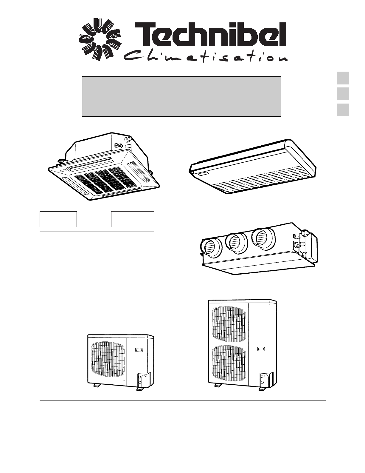
Split system air conditioner
Condizionatore d'aria split system
Climatiseurs split system
EG
I
F
CA250R5TA*
CA360R5TA*
CA480R5TA*
SPA250R5TA*
SPA360R5TA*
SPA480R5TA*
DSAV250R5TA*
DSAV360R5TA*
DSAV480R5TA*
CAV250R5TA*
CAV360R5TA*
CAV480R5TA*
SPAV250R5TA*
SPAV360R5TA*
SPAV480R5TA*
DSAV250R5TA*
DSAV360R5TA*
DSAV480R5TA*
R 22
Dear User
Thank you for selecting this product and we welcome you to the growing family of
satisfied products owners.
Like all products, it has been designed carefully and manufactured under strict quality
control.
We firmly believe that our products will give full satisfaction to users through proper
operation and maintenance.
Please read this manual, and be sure to keep it handy for your reference.
MODEL COMBINATIONS
CONTENTS
SEMI-CONCEALED MODEL
HEAT PUMP VERSION
INDOOR UNIT OUTDOOR UNIT
CA250R5 GR250R5
GR250R7
CA360R5 GR360R7
CA480R5 GR480R7
CEILING-MOUNTED MODEL
HEAT PUMP VERSION
INDOOR UNIT OUTDOOR UNIT
SPA250R5 GR250R5
SPAV250R5 GR250R7
SPA360R5 GR360R7
SPAV360R5
SPA480R5 GR480R7
SPAV480R5
CONCEALED DUCT MODEL
Combine indoor and outdoor units as listed above.
IMPORTANT: Please Read Before Starting
IMPORTANT: Precautions for new refrigerant R 407 C installation
1. GENERAL . . . . . . . . . . . . . . . . . . . . . . . . . . . . . . . . . . . . . . . . . . . . . . . . . . . . . . . . . . . . . . . . . . . . . . . . . . . . . . . . page 4
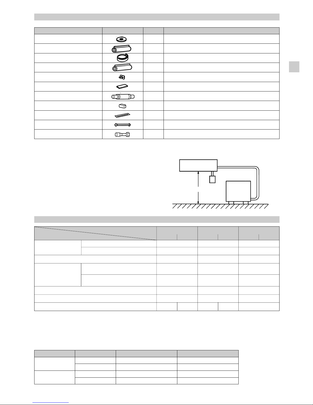
1-1. Tools required for Installation (not supplied)
1-2. Accessories Supplied with Unit
1-3. Type of copper Tube and Insulation Material
1-4. Additional materials required for Installation
1-5. Tubing Lenght
1-6. Operating Limits
2. INSTALLATION SITE SELECTION . . . . . . . . . . . . . . . . . . . . . . . . . . . . . . . . . . . . . . . . . . . . . . . . . . . . . . . . . . . . . page 7
Indoor Unit
Outdoor Unit
2-1. Air discharge chamber for top discharge
2-2. Installing the unit in heavy snow areas
2-3. Precautions for installation in heavy snow areas
2-4. Dimensions of snow/wind-proof ducting
2-5. Wind shield
3. HOW TO INSTALL THE INDOOR UNIT . . . . . . . . . . . . . . . . . . . . . . . . . . . . . . . . . . . . . . . . . . . . . . . . . . . . . . . . . page 9
■4-WAY AIR DISCHARGE SEMI-CONCEALED TYPE . . . . . . . . . . . . . . . . . . . . . . . . . . . . . . . . . . . . . . . . . . . . . . . page 9
3-1. Suspending the Indoor Unit
3-2. Preparation for Suspending
3-3. Burying Inside the Ceiling
3-4. Installing the Drain Piping
3-5. Checking the Drainage
■CEILING-MOUNTED TYPE . . . . . . . . . . . . . . . . . . . . . . . . . . . . . . . . . . . . . . . . . . . . . . . . . . . . . . . . . . . . . . . . . . page 11
3-6. Suspending the Indoor Unit
3-7. Duct for fresh air
3-8. Installing the drain piping
■CONCEALED-DUCT TYPE (DSAV Type) . . . . . . . . . . . . . . . . . . . . . . . . . . . . . . . . . . . . . . . . . . . . . . . . . . . . . . . . page 14
3-9. Required Minimun Space for Installation and Service
3-10. Suspending the Indoor Unit
3-11. Installing the Drain Piping
3-12. Increasing the Fan Speed
3-13. Checking the Drainage
4. HOW TO INSTALL THE OUTDOOR UNIT . . . . . . . . . . . . . . . . . . . . . . . . . . . . . . . . . . . . . . . . . . . . . . . . . . . . . . . page 17
4-1. Removing the Protective Spacer for Transportation
4-2. Installing the Outdoor Unit
4-3. Tubing Direction
EG
R
2
2
HEAT PUMP / COOLING ONLY VERSION
INDOOR UNIT OUTDOOR UNIT
CAV250R5 GRV250L5/R5
GRV250L7/R7
CAV360R5 GRV360L7/R7
CAV480R5 GRV480L7/R7
R
4
0
7
C
HEAT PUMP / COOLING ONLY VERSION
INDOOR UNIT OUTDOOR UNIT
SPAV250R5 GRV250L5/R5
GRV250L7/R7
SPAV360R5 GRV360L7/R7
SPAV480R5 GRV480L7/R7
HEAT PUMP / COOLING ONLY VERSION
INDOOR UNIT OUTDOOR UNIT
DSAV250R5 GR250R5
GR250R7
DSAV360R5 GR360R7
DSAV480R5 GR480R7
1
HEAT PUMP VERSION
INDOOR UNIT OUTDOOR UNIT
DSAV250R5 GR250R5
GR250R7
DSAV360R5 GR360R7
DSAV480R5 GR480R7

2
EG
5. ELECTRICAL WIRING . . . . . . . . . . . . . . . . . . . . . . . . . . . . . . . . . . . . . . . . . . . . . . . . . . . . . . . . . . . . . . . . . . . . . . page 18
5-1. General Precautions on Wiring
5-2. Recommended Wire Lenght and Wire Diameter for Power Supply System
5-3. Wiring System Diagrams
6. HOW TO INSTALL THE REMOTE CONTROLLER (OPTIONAL PART) . . . . . . . . . . . . . . . . . . . . . . . . . . . . . . . . page 21
6-1. When Using a Wall Box for Flush Mounting
6-2. Basic Wiring Diagram
6-3. Wiring System Diagram for Group Control
6-4. Wiring System Digram for Multi-Remote Control
6-5. Meaning for Alarm Message
7. HOW TO INSTALL THE WIRELESS REMOTE CONTROLL UNIT (OPTIONAL PART) . . . . . . . . . . . . . . . . . . . . page 25
■4-WAY AIR DISCHARGE SEMI-CONCEALED TYPE . . . . . . . . . . . . . . . . . . . . . . . . . . . . . . . . . . . . . . . . . . . . . . . page 25
7-1. Indicator Section Installation
7-2. Operating Controler Installation
■CEILING-MOUNTED TYPE . . . . . . . . . . . . . . . . . . . . . . . . . . . . . . . . . . . . . . . . . . . . . . . . . . . . . . . . . . . . . . . . . . page 26
7-3. Indicator Section Installation
7-4. Operating Controller Installation
7-5. Electrical Wiring
7-6. Room temperature Sensor Setting
7-7. Address Switches
7-8. Setting the Model Code (only for Heat Pump models)
7-9. Test Run switch
7-10. Misoperation Alarm Indicators (only for Heat Pump models)
7-11. Wireless Remote controller Installation
7-12. How to install batteries (only for Heat Pump models)
8. HOW TO INSTALL THE WEEKLY TIMER (OPTIONAL CONTROLLER) . . . . . . . . . . . . . . . . . . . . . . . . . . . . . . . page 30
8-1. When Using a Wall Box for Flush Mounting
8-2. Wiring Diagram
8-3. Test Run Setting
8-4. Memory Back Up Function for Power Failure Compensation
8-5. State at Time of Power ON
9. HOW TO PROCESS TUBING . . . . . . . . . . . . . . . . . . . . . . . . . . . . . . . . . . . . . . . . . . . . . . . . . . . . . . . . . . . . . . . . . page 32
9-1. Connecting Tubing Side
9-2. Connecting Tubing between Indoor and Outdoor Unit
9-3. Insulation of refrigerant Tubing
9-4. Taping the Tubes
9-5. Finishing the Installation
10. AIR PURGING . . . . . . . . . . . . . . . . . . . . . . . . . . . . . . . . . . . . . . . . . . . . . . . . . . . . . . . . . . . . . . . . . . . . . . . . . . . . . page 34
11. HOW TO INSTALL THE CEILING PANEL . . . . . . . . . . . . . . . . . . . . . . . . . . . . . . . . . . . . . . . . . . . . . . . . . . . . . . . page 36
■4-WAY AIR DISCHARGE SEMI-CONCEALED TYPE . . . . . . . . . . . . . . . . . . . . . . . . . . . . . . . . . . . . . . . . . . . . . . . page 36
11-1. Before Installing the Ceiling Panel
11-2. Installing the Ceiling Panel
11-3. When Removing the Ceiling Panel for Servicing
11-4. Adjusting the Motor Flap
12. TEST RUN . . . . . . . . . . . . . . . . . . . . . . . . . . . . . . . . . . . . . . . . . . . . . . . . . . . . . . . . . . . . . . . . . . . . . . . . . . . . . . . . page 38
12-1. Preparing for Test Run
12-2. PCB Setting
12-3. R.C. Address Setting Method
12-4. Automatic Address Setting Method
12-5. Test Run Procedure
12-6. Items to Check Prior to Test Run
12-7. The Main Alarms of Mis-wiring & Mis-setting
12-8. The Main Alarms of Unit Troubles
12-9. The Main Alarms of Power Supply Troubles
13. PUMP DOWN. . . . . . . . . . . . . . . . . . . . . . . . . . . . . . . . . . . . . . . . . . . . . . . . . . . . . . . . . . . . . . . . . . . . . . . . . . . . . . page 42
IMPORTANT PLEASE READ BEFORE STARTING
This air conditioning system meets strict safety and operating standards. As the installer or service person, it is an important part
of your job to install or service the system so it operates safely and efficienly.
For safe installation and trouble-free operation, you must:
• Carefully read this instruction booklet before beginning.
• Follow each installation or repair step exactly as shown.
• Observe all local, state, and national electrical codes.
• Pay close attention to all warning and caution notices given in this manual.
Outer diameter ø 6.35 ø 9.52 ø 12.7 ø 15.88 ø 19.05 ø 22.2 ø 25.4 ø 28.58
Wall thickness 0.8 0.8 0.8 1.0 1.0 1.2 1.0 1.0
3
EG
WARNING • This symbol refers to
a hazard or unsafe
practice which can
resuklt in severe
personal injury or
death.
IN CASE OF IMPROPER INSTALLATION
The manufacturer shall in no way be responsible for improper
installation or maintenance service, including failure to follow
the instruction in this document.
When Transporting
Be careful when pocking up and moving the indoor and outdoor
units. Get a partner to help, and bend your knees when lifting
to reduce strain on your back. Sharp edges or thin aluminum
fins on the air conditioner can cut your fingers.
When Installing
…In a Room
Properly insulate any tubing run inside a room to prevent
“sweating” that can cause driping and water damage to walls
and floors.
…In Moist or Uneven Locations
Use a raised concrete pad or concrete blocks to provide a
solid, level foundation for the outdoor unit. This prevents water
damage and abnormal vibration.
…In an area with High Winds
Securely anchor the aoutdoor unit down with bolts and a metal
frame. Provide a suitable air baffle.
When Connecting Refrigerant Tubing
• Executive enough ventilation in case refrigerant gases leak
during operations. Be careful that the contact of the
refrigerant gases with the flare will cause the generation of
poisonous gases.
• Keep all tubing runs as short as possible.
• Use the flare method for connecting tubing.
• Apply refrigerant lubricant to the matching surfaces of the
flare and union tubes before connecting them, then tighten
the nut with a torque wrench for a leak-free connection.
• Check carefully for leaks before starting the test run.
When Servicing
• Turn the power OFF at the main power box (mains) before
opening the unit to check or repair electrical parts and wiring.
• Keep your fingers and clothing away from any moving parts.
• Clean up the site after you finish, remembering to check
that no metal scraps or bits of wiring have been left inside
the unit being serviced.
CAUTION • This symbol refers to
a hazard or unsafe
practice which can
resuklt in personal
injury or product or
property damage.
SPECIAL PRECAUTION
• ELECTRICAL SHOCK CAN CAUSE SEVERE
PERSONAL INJURY OR DEATH. ONLY A
QUALIFIED, EXPERIENCED ELECTRICIAN
SHOULD ATTEMPT TO WIRE THIS SYSTEM.
When Wiring
• Do not supply power to the unit until all wiring and tubing are
completed or reconnected and checked.
• Highly dangerous electrical voltage are used in this system.
Carefully refer to the wiring diagram and these instruction
when wiring. Improper connections and inadequate
grounding can cause accidentaly injury or death.
•Ground the unit following local electrical codes.
• Connect all witing tightly. Loose wiring may cause
overheating at connection points and a possible fire hazard.
PRECAUTIONS FOR NEW REFRIGERANT R 407 C INSTALLATION
1. Care regarding piping
1-1. There is no need to change piping and tube wall thickness. Use refrigerant pipes of the same wall thickness as R22.
Type 0 1/2 H, H
Copper tube
* C 1220 type with JIS H 3300 designation (Copper Pipe and Copper Alloy Seamless Pipe)
1-2. Prevent impurities including water, dust and oxide
from coming into the pipe. Impurities can cause R407C
refrigerant deterioration and compressor defects. Due
to the different features of the refrigerant and
refrigerating machine oil, the prevention of water and
other impurities becomes more important than ever.
2. Make sure to refill the refrigerant in liquid form
2-1. Since R 407 C is a non-azeotrope, refilling the
refrigerant in gas form can lower performance and
cause defects of the unit.
2-2. Since refrigerant composition changes and
performance decreases when gas leaks, collect the
remaining refrigerant and refill the required total amount
of new refrigerant after fixing the leak.
3. Different tools
3-1. Tools specs have been changed due to the features
of R 407 C. Some of the R 22 tools cannot be used.

Vacuum
pump
4
1. GENERAL
This booklet briefly outlines where and how to install the air
conditioning system. Please read over the entire set of
instructions for the indoor and outdoor units and make sure all
accessory parts listed are with the system before beginning.
1-1. Tools Required for Installation (not
supplied)
1. Standard screwdriver
2. Phillips head screwdriver
3. Knife or wire stripper
4. Tape measure
5. Level
6. Sabre saw or key hole saw
7. Hacksaw
8. Core bits
9. Hammer
10. Drill
11. Tube cutter
12. Tube flaring tool
13. Tourque wrench
14. Adjustable wrench
15. Reamer (for deburring)
1-2. Accessories Suppled with Unit
See Table 1-1 to 1-3.
Table Type
1-1 4-Way AirDischarge Semi-Concealed
1-2 Ceiling-Mounted
1-3 Concealed-Duct
1-3. Type of Copper Tube and Insulation
Material
To purchase these material from a local source, you will need:
1. Deoxidized annealed copper tube for refrigerant tubing.
2. Foamed polyethylene insulation for 15.88 mm (5/8”) or
19.05 mm (3/4”) O.D. copper tubes as required to precise
length of tubing. Wall thickness of the insulation should
be not less than 8 mm.
3. Use insulated copper wire for field wiring. Wire size varies
with the total length of witing. Refer to Section 5. Electrical
Wiring for details.
EG
Gauge manifold
Vacuum pump
Outlet
Inlet
Liquid
Valve
Product name
Gauge
manifold
Charge
hose
Leak
detector
Flaring oil
New
tools
Yes
Yes
Yes
Yes
Yes
R22 tools
compatible
with R407C
No
No
Yes
No
No
Remarks
Types of refrigerant and refrigerating machine oil, and pressure
gauge are different.
To resist pressure and oil, material has been changed.
Use a conventional vacuum pump if it is equipped with a check
valve. If it has no check valve, purchase and attach a vacuum
pump adaptor.
Leak detector for CFC an HCFC which react to chlorine do not
function because R407C contains no chlorine. Leak detector for
R407C can be used for HFC134a.
Mineral oil (for example, suniso oil) can be used as R22 oil. Use
synthetic fluid (for example, ether oil) as R407C oil.
* Using both R22 tools and new tools together can cause defects.
3-2. Use a R407C exclusive cylinder only. Single-outlet valve
(with siphon tube).
Liquid refrigerant can be
refilled standing it up
straight.
New refrigerant R407C cannot be used for existing models.
1. Compressor specs are different.
When refilling the R22 compressor with R407C, durability will significantly decrease since some
of the materials used for compressor parts are different.
2. Existing piping cannot be used.
Completely cleaning out residual refrigerating machine oil is impossible, even by flushing.
3. Refrigerating machine oil differs.
Since R22 refrigerating machine oil is mineral oil, it does not dissolve in R407C. Therefore,
refrigerating machine oil discharged from the compressor can cause compressor damage.
R22 refrigerating machine oil Mineral oil (suniso oil)
R407C refrigerating machine oil Synthetic fluid (ether oil)
R 407 C

5
1-4. Additional Materials Required for
Installation
1. Refrigeration (armored) tape
2. Insulated staples or clamps for connecting wire
(See your local codes.)
3. Putty
4. Refrigeration tubing lubricant
5. Clamps or saddles to secure refrigerant tubing
CAUTION • Check local electrical
codes and regulations
before obtainig wire.
Also, check any
specified instructions
or limitations.
Part Name Figure Q’ty Remarks
Full-scale installation diagram 1 For determinig suspension bolt pitch
Flare insulator 2 For wide and narrow tubes
Installation gauge 1 For adjusting the unit position
Insulating tape 1 For wide tube flare nuts
Hose band 2 For Securing drain hose
Packing 1 For drain joint
Dran insulator 1 For drain joint
Drain hose 1 For drain hose joint
Sealing putty 1 For sealing recessed portion of power supply
Tube connector 1
For sizing up of narrow tube from 6.35 to 9.52 (only for 25 type)
Table 1-1. 4-Way Air Discharge Semi-Concealed
Table 1-2. Ceiling-Mounted
(White-for
insulating)
Part Name Figure Q’ty Remarks
Special washer 4 For suspending indoor unit from ceiling
Drain insulator 1 For drain hose joint
Flare insulator 1 Set For drain narrow tube joints
Drain hose clamp 4 For drain hose joint
2 For rubber cap (in case of using left side drain pipe)
Insulating tape 2 For wide flare joint
Vinyl clamp 8 For ends of flare insulator
Sealing insulator
1 For sealing top face
1 For sealing rear face
Grommet 1 For power supply inlet
Full-scale installation diagram 1 For determining suspension bolt pitch
Sealing putty 1 For sealing recessed portion of power supply
Owner’s manual 1 –
Drain hose 1 For drain hose joint
Tube connector 1
For sizing up of narrow tube from 6.35 to 9.52 (only for 25 type)
White
(heat-resisting)
T10
T3T5
EG
Special washer 8 For suspending indoor unit from ceiling
Flare Insulator 2 For wide and narrow tubes
Insulating Tape 1 For wide and narrow tubes flare nuts
Drain Insulator 1 For drain hose joint
Hose band 2 For securing drain hose
Packing 1 For drain joint
Drain hose 1
Sealing putty 1 For sealing recessed portion of power supply
Vinyl clamp 8 For flare insulator
Booster cable* 1 For increasing the fan speed
Tube connector 1
For sizing up of narrow tube from 6.35 to 9.52 (Only for 25 type)
6
Booster cable is housed inside the electrical component box.
1-5. Tubing Length
• Refrigerant tubing between the indoor and outdoor
units shall be kept as short as possible
• The length of the refrigerant tubes between the
indoor and outdoor units are limited by the elevation
difference between the two units. During tubing
work, try to make both the tubing length (L) and
the difference in elevation (H) as short as possible.
Refer to Table 1-4 for the details.
Installation Example 1
INDOOR
UNIT
Tubing length (L)
OUTDOOR
UNIT
Elevation difference (H)
Table 1-3. Concealed-Duct
Table 1-4.
6.35 (1/4)
15.88 (5/8)
50
50
30
30
a) 45
3.0 3.2
Tubing size Narrow tube mm(in.)
outer diameter Wide tube mm (in.)
Limit of tubing length (m)
Outdoor unit is placed upper (m)
Limit of elevation
difference between
the two units Outdoor unit is placed lower (m)
Max. allowable tubing length at shipment (m)
Required additional refrigerant*
1
(g/m)
Refrigerant charged at shipment (kg)
9.52 (3/8)
19.05 (3/4)
50
50
30
30
b) 50
3.5 4.0
9.52 (3/8)
19.05 (3/4)
50
50
30
30
b) 50
4,5
Models
Tubing Data
No additional charge of compressor oil is necessary.
*1 If total tubing length becomes 30 to 50 , charge additional refrigerant by a) 45 or b) 50 g/m.
EG
425 type
R22 R407C
436 type
R22 R407C
448 type
R22 R407C
1-6. Operating limits
Temperature Indoor air intake temp. Outdoor air intake temp.
Maximum 35°C DB / 25°C WB 43°C DB
Cooling Minimum 18°C DB / 14°C WB – 5°C DB (–15°C DB*)
Maximum 27°C DB 21°C DB / 15.5°C WB
Heating Minimum 15°C DB – 15°C WB
* R407C models only
Part Name Figure Q.ty Remarks
Ceiling-Mounted Type
DO:
• select an appropiate position from which every corner of the
room can be uniformly cooled.
• select a location where the ceiling is strong enough to support
the weight of the unit.
• select a location where tubing and drain pipe have the
shortest run to the outside.
• allow room for operation and maintenance as well as
unrestricted ai flow around the unit.
• install the unit within the maximum elevation difference (H)
above or below the outdoor unit and within a total tubing
length (L) from the outdoor unit as detailed in table 1-4.
• allow room for mounting the remote controller about 1 moff
the floor, in an area that is not in direct sunlight nor in the flow
of cool air from the indoor unit.
7
NOTE
Air delivery will be degraded if the distance from the floor to
the ceiling is greater than 3 m.
4-Way Semi-Concealed Type
Ceiling
Wall
25 cm min.
Air
discharge
Side view
Air intake
30 cm
min.
25 cm min.
NOTE The rear of the indoor unit can be installed
flush against the wall.
Front view
1 m
1 m
1 m
1 m
1 m
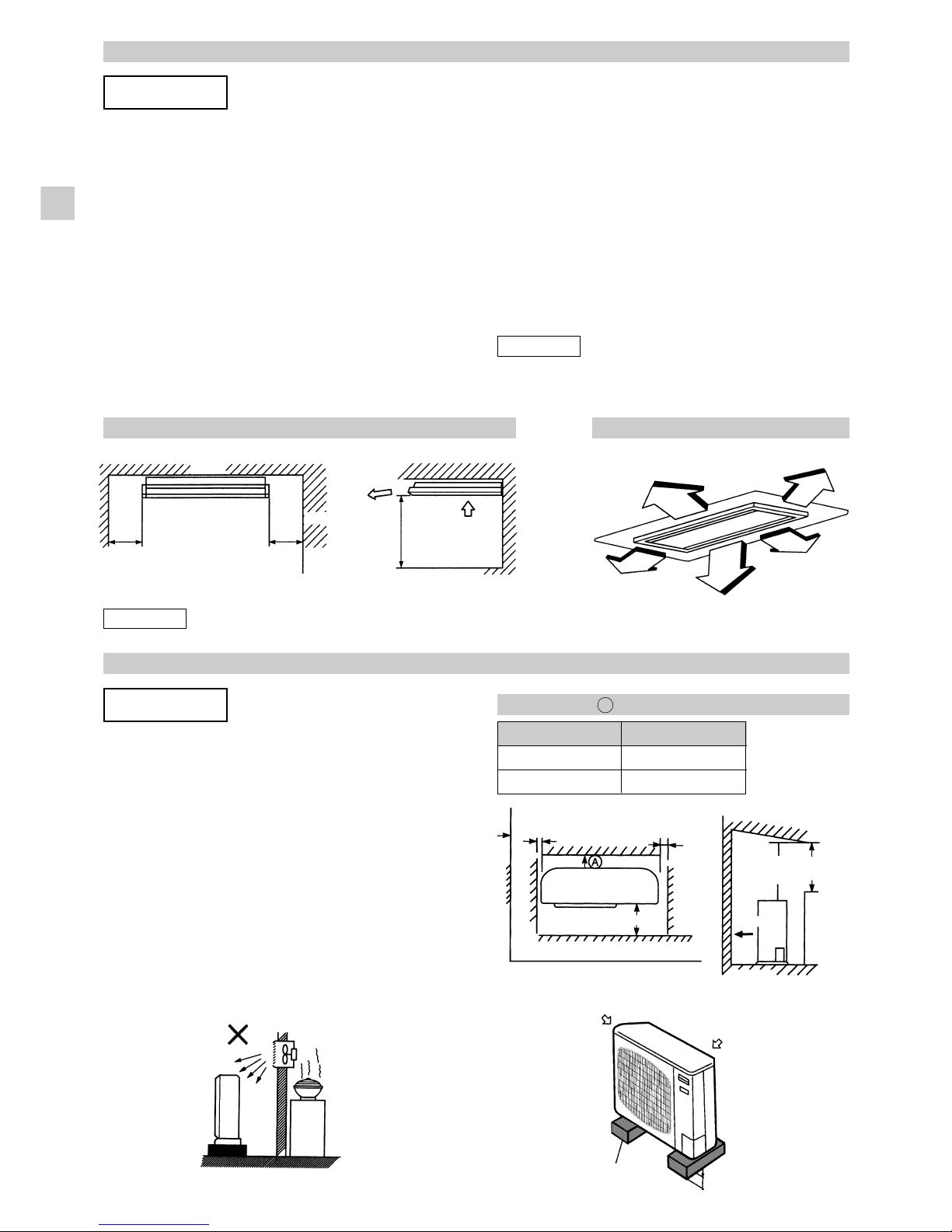
AVOID:
• heat source, exhaust fans, etc. (Fig. 2-1).
• damp, humid or uneven locations.
DO:
• choose a place as cool as possible.
• choose a place that well ventilated and autside air
temperature does not exceed maximum 45 °c constantly.
• allow enough room around the unit for air intake/exhaust
and possible maintenance. (Fig. 2-2).
• provide a solid base; about 15 cm above ground level to
reduce humidity and possible water damage in unit and
drecrease service life. (Fig. 2-3).
• use lug bolts or equal to bolt down unit, reducing vibration
and noise.
OUTDOOR UNIT
Air in Air in
Min. 15 cm
Air
discharge
Anchor bolts
(4 pieces)
Model Min. (cm)
425 type 10
436, 448 type 20
Fig. 2-3
Hot air
Out-
door
unit
Exhaust fan
Heat
source
Fig. 2-1
Fig. 2-2
Min.
1 cm Min.
1 cm
Min.
2 m
Ground
Min.
2 m
Obstacle
Air
dis-
charge
Min. 50 cm
Obstacle above
Table 2-1 Dimension
A
➩
2. INSTALLATION SITE SELECTION
AVOID:
• areas where leakage of flammable gas may be expected.
• places where large amounts of oil mist exist.
• direct sunlight.
• location where nearby heat sources may affect performance
of the unit.
• locations where nearby external air may enter the room
directly. This may cause “sweating” in the air discharge ports,
causing them to spray or drip.
• location where the remote controller will be splashed with
water or affected by dampness or humidity.
• installing the remote controller behind curtains or furniture.
INDOOR UNIT
EG

8
Min. 1 m Min. 1 m Min. 1 m Min. 1 m
Min. 20 cm
Min. 35 cm
Min. 35 cm
Min. 30 cm
Min. 30 cm
Air
discharge
chamber
Min. 1.5 m
Min. 30 cm
Min. 35 m
Min. 20 cm
In case of multiple installations
■ Unit spacing if air discharge chamber is not used. ■ Unit spacing when air dscharge chamber is used.
* If you would like to make the separation smaller on the
air discharge side, use an air discharge chamber.
* Your can install any number of units side-by-side.
* Only up to 3 units can be install side-by-side under the
above conditions. the next group must be spaced at
least 30 cm away from the first group.
2-1. Air Discharge Chamber for Top
Discharge
Be sure to install the air discharge chamber in the field
when:
• it is difficult to keep a space of min. 50 cm between
the air discharge outlet and the obstacle.
• The air discharge outlet is facing to the sidewalk and
discharged hot air annoys the passers.
Refer to Fig. 2-4.
2-2. Installing the Unit in Heavy Snow
Areas
In positions with strong wind, snow-proof ducting
should likewise be fitted and direct exposure to the
wind should be avoided as much as possible.
Countermeasures against snow and wind in regions
with snow and strong wind, the following problems
may occur when the outdoor unit is not provided with
a platform and snow-proof ducting.
a) The outdoor fan may not run and damage of the
unit may be caused.
b) There may be no air flow.
c) The tubing may freeze and burst.
d) The condenser pressure may drop because of
strong wind, and the indoor unit may freeze.
2-3. Precautions for Installation in Heavy
Snow Areas
1) The platform should be higher than the max, snow
depth. (Fig. 2-5).
2) The two fixing feet of the outdoor unit should be
used for the platform, and the platform should be
installed beneath the air intake side of outdoor
unit.
3) The platform foundation must be firmer and the
unit must be secured with anchor bolts.
4) In case of installation on a roof subject to strong
wind, countermeasures must be taken to prevent
the unit from being blown over.
Air discharge
Fig. 2-4
In regions with snow fall, the outdoor unit should be provided
with a platform and snow-proof duct.
Without snow-
proof ducting
(Low platform)
With snow-proof
ducting
(High platform)
Fig. 2-5 Fig. 2-6
Air
Intake
Platform (foundation)
Higher than the
maximum
snow depth
Duct
About 1/2 of the
unit height
Air
Intake
Duct
Outdoor
Unit
Example of Installation
Duct
Duct
Outdoor Unit
Min. 100
300
Min. 100 300 Unit: mm
2-4. Dimensions of Snow/Wind-proof
Ducting and Refrigerant Tubing Space
for Installation
EG

9
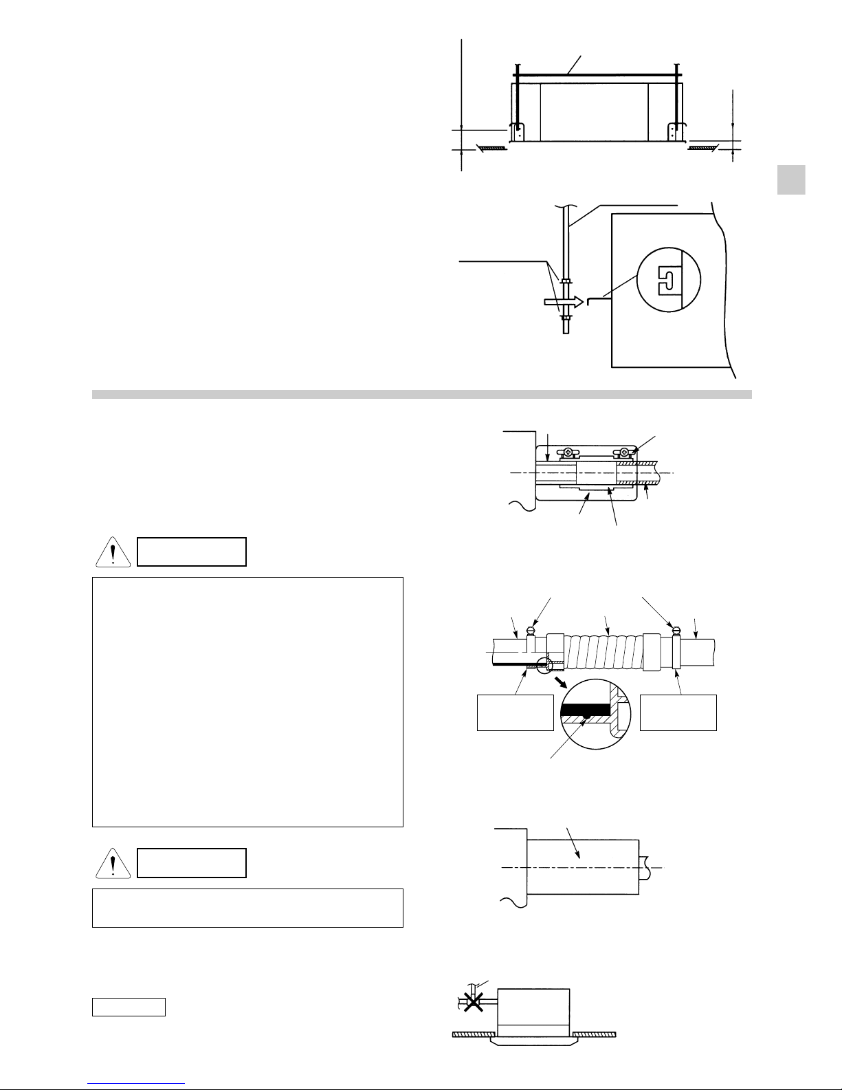
■4-WAY AIR DISCHARGE SEMI-CONCEALED TYPE
EG
3-1. Suspending the Indoor Unit
This unit uses a drain pump. Use a carpenter’s level to check
that the unit is level.
3-2. Preparation for Suspending
(1) Fix the suspension bolts securely in the ceiling using
the method shown in the drawings (Figs. 3-1 / 3-2 /
3-3), by attaching them to the ceiling support structure,
or by any other method that insures that the unit will
be securely and safely suspended.
(2) Follow Fig. 3-2 and Table 3-1 to make the holes in the
ceiling.
Model A B
425 type 820 730
436, 448 type 1110 1020
3) Determine the pitch of the suspension bolts using the
provided full-scale installation diagram. The diagram
and table (Fig. 3-3 and Table 3-3) show the relationship
between the position of the suspension fitting, the unit,
and the panel.
Model ABCDE
425 type 150 200 255 298 125
436, 448 type 165 235 285 328 125
Hole-in-anchor
Hole-in-plug Concrete Insert
Suspension bolt (M10 or 3/8’’)
(field supply)
A (ceiling opening dimension)
B (suspension bolt itch)
Electrical component box
Refrigerant
tubing side
Drain hose
side
Refrigerant tubing joint (narrow tube side)
Refrigerant tubing joint (wide tube side)
Drain inspection port
Suspension lug
Power supply inlet
Unit: mm
820 (ceiling opening dimension)
590 (suspension bolt pitch)
Fig. 3-1
Fig. 3-3
Fig. 3-2
3. HOW TO INSTALL THE INDOOR UNIT
Table 3-1
Table 3-2
Unit: mm
Unit: mm
2-5. Wind Shield for “SHL”, “SCL” Model
It is recommended to install wind shields for cooling operation
in low outdoor temperature condition. (Fig. 2-8).
General
When the outdoor unit is installed in a position exposed to
strong wind (like seasonal winds with low air temperature in
winter), wind shield must be installed on the outdoor unit.
This unit is designed so that the fan of the outdoor unit runs at
low speed when the air conditioner is operated at low outdoor
air temperatures. When the outdoor unit is exposed to strong
wind, the system pressure drops because of the freeze protector.
For outer dimensions of wind shield, please see Fig. 2-9.
IMPORTANT
Fig. 2-8
Wind shield
(air discharge side)
Front
3 - ø60 hole
8 - ø6 hole
450 100250250
1116
132
567
131
300
592
3 - ø40 hole
6 - ø6 hole
25054924
132
57013
596
554
13125025027
554
For 436,448 type
For 425 type
Fig. 2-9
Recommended outer dimensions
of wind shield (field supply).
10
EG
3-3. Burying inside the Ceiling
(1) When placing the unit inside the ceiling, determine the
pitch of the suspension bolts using the provided full-
scale installation diagram. (Fig. 3-4).
Tubing and wiring must be laid inside the ceiling when
suspending the unit. If the ceiling is already constructed,
lay the tubing and wiring into positiion for connection
to the unit before placing the unit inside the ceiling.
(2) The length of suspension bolt must be so that the
distance between the bottom of the bolt and the bottom
of the ceiling is more than 60 mm as shown in Fig. 3-4.
(3) Thread the 2 hexagonal nuts and washers (field supply)
onto the 4 suspension bolts as shown in Fig. 3-5.
Use 2 sets of nuts and washers (upper and lower), so
that the unit with not fall off the suspension lugs.
(4) Remove the protective cardboard used to protect the
fan parts during transport.
(5) Adjust the distance between the unit and surface of
the ceiling (48 mm) using the supplied installation
gauge. (Fig. 3-4).
3-4. Installing the Drain Piping
(1) Prepare a standard hard (PVC) pipe (O.D. 32 mm) for
the drain and use the accessory drain hose and hose
band to prevent water leaks.
The PVC pipe must be purchase separately.
The transparent part allows you to check drainage.
(Fig. 3-6).
Full-scale installation drawiong
(provided)
Transparent part for
checking drainage Hose band (supplied)
Hard PVC pipe
pipe (not supplied)
Drain hose (supplied)
Packing (supplied)
Nuts and washers
(2 sets)
Suspension bolt
Suspension lug
Uppper
Lower
More than 60 mm
48 mm
Fig. 3-4
Fig. 3-5
CAUTION
• Tighten the hose band firmly after the supplied drain
hose has been inserted to touch the ends of both of the
connection pipes, as shown in Fig. 3-7.
• Do not use an adhesive when connecting the supplied
hose.
Reasons:
1. It may cause water to leak from the connection. Sin-
ce the connection is slippery just after the adhesive has
been applied, the pipes easily slip off.
2. The pipes cannot be removed when maintenaces is
needed.
• Do not bend the supplied drain hose 90° or more. The
hose may slip off.
• Align the hose bands with the ends of the hoses. Ti-
ghten the hose bands firmly. PLease make sure that the
stopper is not covered by the hose band, as shown in
Fig. 3-7.
CAUTION
• Tighten the hose clamps so their locking nuts face
upward (Fig. 3-6).
(2) After checking the drainage, wrap the supplied packing
and drain pipe insulator around the pipe. (Fig. 3-8.)
NOTE
Make sure the drain pipe has a downward gradient (1/100 or
more) and that there are no water traps.
Fig. 3-6
Fig. 3-7
Drain insulator (supplied)
Air bleeder
Fig. 3-8
Fig. 3-9
Stopper
Hose band Supplied
drain hose
Drain pipe
(not supplied)
Connection
pipe
Hose band
Align the hose
band with the end
of the pipe
Align the hose
band with the end
of the pipe

11
EG
3-5. Checking the Drainage
After wiring and piping are completed, use the following procedure to check that the water will drain smoothly. For this, prepare a
bucket and wiping cloth to catch and wipe up spilled water.
(1) Connect power to the power terminal board (L, N terminal) inside the electrical component box.
(2) Remove the tube cover and through the opening, slowly pour about 1,200 cc of water into the drain pan to check drainage.
(3) Short the check pin (CN5 withe) on the indoor control main board and operate the drain pump. Check the water flow and see
if there is any leakage.
CAUTION •Be careful since the
fan will start when you
short the pin on the in-
door control board.
(4) When drain checking is finished, open the check pin
(CN5 white) and remount the tube cover.
CAUTION •To mount the tube co-
ver, use 4 x 8 tapping
screws. Do not use
long screws as they
may puncture the
drain pan and cause
water leakage.
4 x 8 mm
tapping screw
Tube cover
Front face
Rear
Full-scale diagram
Hole-in-anchor
Hole-in-plug Concrete Insert
Suspension bolt (M10 or 3/8’’)
(field supply)
Fig. 3-13
■CEILING-MOUNTED TYPE
3-6. Suspending the Indoor Unit
(1) Place the full-scale diagram (supplied) on the ceiling
at the spot where you want to install the indoor unit. Use
a pencil to mark the drill holes. (Fig. 3-14).
NOTE
Since the diagram is made of paper, it may shrink or stretch
slightly because of high temperature or humidity. For this
reason, before drilling the holes maintain the correct dimensions
between the markings.
(2) Drill holes at the 4 points indicated on the fullscale
diagram.
(3) Depending on the ceiling type:
a) Insert suspension bolts as shown in Fig. 3-15.
or
b) Use existing ceiling supports or construct a suitable
support as shown in Fig. 3-16.
Fig. 3-14
Fig. 3-15
CAUTION
•Do not install an air bleeder, as this may cause water
to spray from the drain tube outlet. (Fig. 3-9)
•If it is neccesary to increase the height of the drain
pipe somewhat, the portion directly after the connection
port can be raised a maximum of 25 cm. Do not raise
it any higher than 25 cm, as this could result in water
leaks. (Fig. 3-10)
•Do not install pipe with an upward gradient from the
connection port. It will cause the drain water to flow
backwards and leak when the unit is stopped.
(Fig. 3-11)
•Do not apply force to the piping on the unit side when
connecting the drain pipe. The pipe should not be
allowed to hang unsupported from its connection to the
unit. Fasten the pipe to a wall, frame, or other support
as close to the unit as possible. (Fig. 3-12)
•Be sure to provide insulation for any drain piping
installed indoors.
30 cm or less (as short as possible)
25 cm or less
Upward gradient
Support
pieces
Fig. 3-10
Fig. 3-11
Fig. 3-12

12
EG
Ceiling tiles
Ceiling support
A
A
unit
Fixture
Ceiling
surface
Within
50 mm
WARNING
•It is important that you use extreme care in supporting
the indoor unit from the ceiling. Ensure that the ceiling
is strong enough to support the weight of the unit.
Before hanging the ceiling unit, test the strength of
each attached suspension bolt.
(4) Screw in the suspensions bolts, allowing them to
protrude from the ceiling as shown in Fig. 3-16. The
distance od each exposed bolt must be of equal length
within 50 mm. (Fig. 3-17)
(5) Before suspending the indoor unit; remove the 2 or 3
screws on the latch of the air-intake grilles, open the
grilles, and remove them by pushing the claws of the
hinges as shown in Fig. 3-18. Then remove both side
panels sliding them along the unit toward the front after
removing the two screws which fix them. (Fig. 3-19).
(6) Preparation for suspending the indoor unit. The
suspension method varies depending on whether the
unit is next to the ceiling or not. (Fig. 3-20 and 3-21).
(7) Suspend the indoor unit as follows.
(a) mount a washer and two hexagonal nuts on each
suspension bolt as shown in Fig. 3-22.
Fig. 3-16
Fig. 3-17
Pul out the Air-
Intake grille
pushing claws
of the hinges Hinge
Screw
Latch
Air-intake grille
Suspension bolt
(field supply)
Ceiling surface
Washer (supplied)
Double nut
(field supply)
Fixture
unit
Slide toward
front side
Sode panel
Ceiling
surface
Nut
(field supply)
Suspension bolt
Washer
(supplied)
Approx.
25 mm
Slide
Fig. 3-18
Suspension bolt
(field supply)
Washer (supplied)
Washer (field supply)
Double nut
(field supply)
unit
Fig. 3-19
Fig. 3-20 Fig. 3-21 Fig. 3-22
Fig. 3-23
Fig. 3-24
(b) Lift the indoor unit, and place it on the washer
throught the notches, so as to fix it in place.(Fig. 3-23)
(c) Tighten the two hexagonal nuts on each suspension
bolt to suspend the indoor unit as shown in Fig. 3-24.
NOTE
A ceiling surface is not always level. Please confirm that the
indoor unit is evenly suspended. For the installation to be
correct, leave a clearance of about 10 mm between the ceiling
panel and the ceiling surface and fill the gap with an appropriate
insulation or filler material.
(8) If the tubing and wiring have to pass towards the rear
of the unit, make holes in the wall. (Fig. 3-25)
(9) Measure the thickness of the wall from the inside to
the outside and cut PVC pipe at a slight angle to fit.
Insert the PVC pipe in the wall. (Fig. 3-26)
NOTE
The hole should be made at a slight downxard slant to the
outside.

13
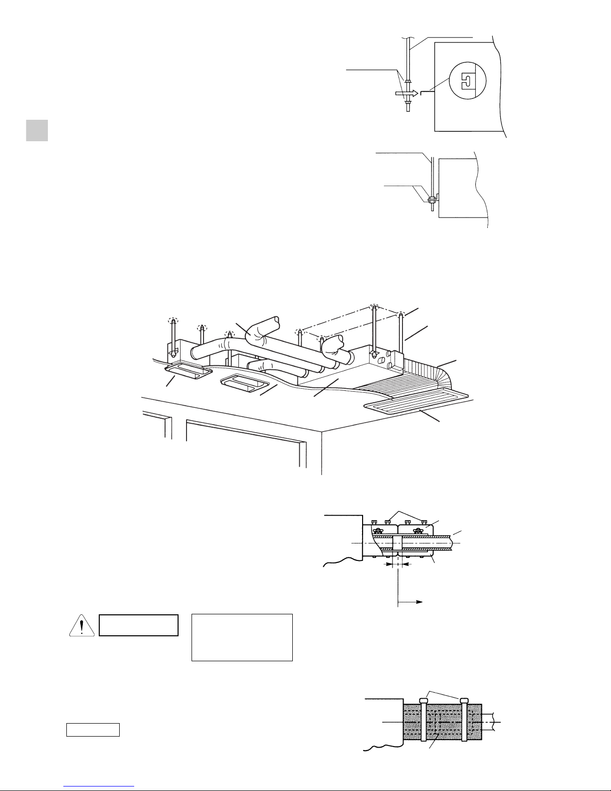
3-7. Duct for Fresh Air
There is a duct connection port (knock-out hole) at the right-
rear on the Panel Top of the indoor unit for drawing in fresh air.
If it is necessary to draw in fresh air, remove the cover by
knocking out and connect the duct to the idoor unit throught the
connection port. (Fig. 3-27)
If connection at the right-rear on the Panel Top is not
appropriate, another duct connection port can be made by
cutting an opening on the left side of the Rear Panel of the
indoor unit as shown in Fig. 3-28.
3-8. Installing the Drain Piping
•Prepare a standar PVC pipe for the drain and connect it to
the indoor unit drain pipe with the supplied hose clamps to
prevent water leaks.
CAUTION
•Tighten the drain pipe clamps so that the locking nuts
are facing upwards. (If tightened with the locking nuts
facing downwards, it may cause water leakage).
•Do not use an adhesive when connecting the drain
hose (supplied) to the drain connection (main unit,
PVC pipe).
•Connect the drain piping so that it slopes downward from
the unit to the outside. (Fig. 3-29)
•Never allow traps to occur in the course of the piping.
•Insulate any piping inside the room to prevent dripping.
•Use the supplied drain pipe to connect the drain pipe with the
drain outlet of the indoor unit.
•After connecting the drain pipe securely, wrap the supplied
drain pipe insulator around the pipe, seal the gap at the drain
socket with the supplied black insulation tape, then secure
it with clamps. (Fig. 3-30)
•After the drain piping, pour water into the drain pan to check
that the water drains smoothly.
CAUTION •Check local electrical
codes and regulations
before obtaining wire.
Also, check any spe-
cified instruction or li-
mitations.
Duct connection port
(Knock-out hole)
Panel Top
Right side
Right side Cut this portion
Fig. 3-27
Fig. 3-28
Fig. 3-29
Fig. 3-30
ABC
425 110 100 100
110 100 150
436 448
Min. 1/100
Good
Not good
Drain hose
(supplied)
Drain pipe camp
(supplied)
Hard PVC pipe
(not supplied)
Vinyl clamp
(supplied)
Packing
(supplied)
EG
Fig. 3-25 Fig. 3-26
Indoor side Outdoor side
PVC pipe (localy purchased) INSIDE OUTSIDE
PVC pipe
Slight
angle
Cut at slight angle
Wall
1,380 490
436, 448 1,442 1,480 1,560 335 310 1,460 1,495 130 240 16 18
(230x6) (245x2)
LM
No. of holes
ABCDEFGH I JK
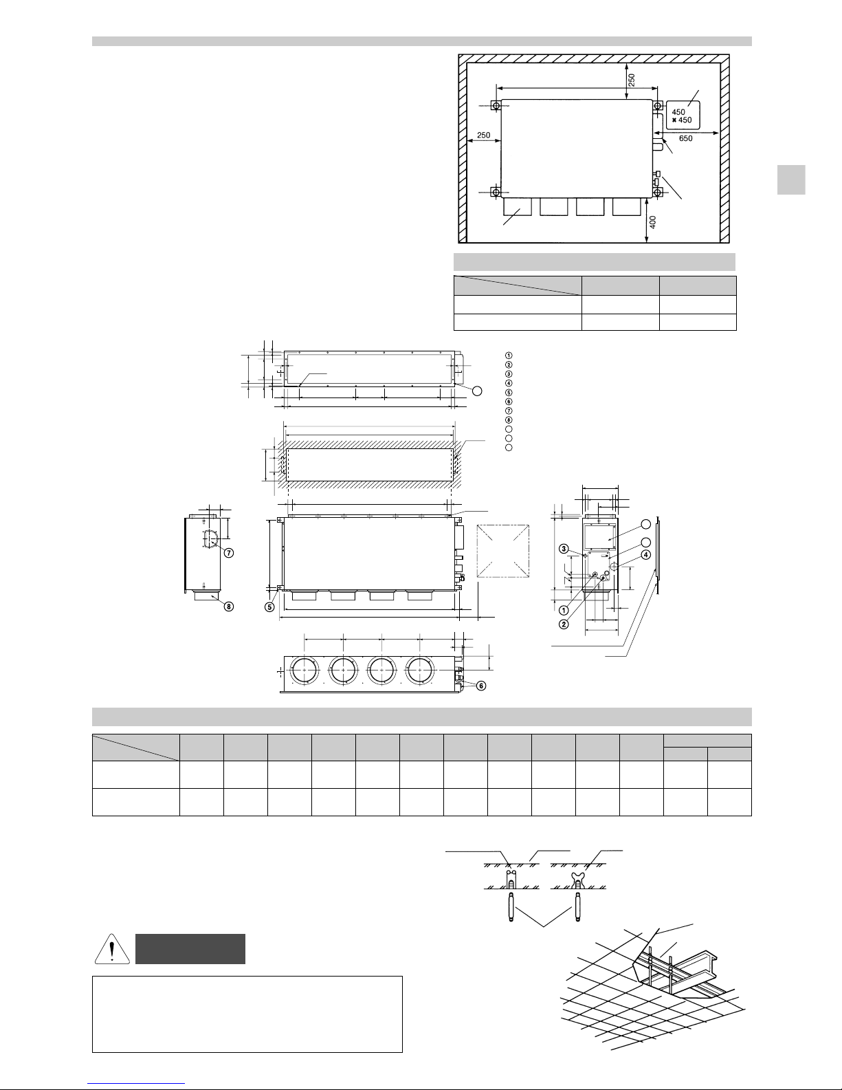
Refrigerant tubing joint (narrow tube)
Refrigerant tubing joint (wide tube)
Upper drain port (O.D. 32 mm)
Bottom drain port (O.D. 26 mm)
Suspension lug
Power supply outlet (2-ø30)
Fresh air intake port (ø150)
Flange for the flexible air outlet duct (ø200)
Tube cover
Electrical component box
Flange for the air intake duct
(Option or field supply)
9
10
9
10
11
11
(Suspension bolt pitch)
(Suspension bolt pitch)
M-ø3.3
(Hole)
4-ø12
(Hole)
(Hole)
A (O.D.)
L-ø6
I
10 10
10
5555 200
10
IJJK
B
C
D (150)
40
EEEF75
65
285
70 130
25 210
310
25
175
35
90 3131
H (Duct suspension bolt pitch)
G (Ceiling opening dimension)
25
100
185
58025
115
190
85
25 70 30
160
630 25
10
88
275
(Ceiling opening dimension)
260
(O.D.)
1919
Inspection access
(450 ×450)
(Field supply)
Inspection access panel
Ceiling
14
Fig. 3-31
Fig. 3-33
Fig. 3-32
■CONCEALED DUCT TYPE (model ADR)
3-9. Required Minimum Space for Instal-
lation and Service
•This air conditioner is usually installed above the ceiling so
that the indoor unit and ducts are not visible. Only the air
intake and air outlet ports are visible from below.
•The minimum space for installation and service is shown in
Table 3-3.
•It is recommended to provide inspection access (450 x 450
mm) for checking and servicing the electrical system.
•Fig. 3-31 and Table 3-4 show the detailed dimensions of the
indoor unit.
3-10. Suspending the Indoor Unit
Depending on the ceiling type:
•Insert bolt anchors as shown in Fig. 3-32.
or
•Use existing ceiling support or construct a suitable support
as shown in Fig. 3-33.
A (Suspension blt pitch) Inspection
access
Electrical
component
box
Refrigerant
tubing
Air outlet duct flange
Indoor Unit
425 Type 436, 448 Type
A1080 1560
Number of duct flanges 34
Model
Model
Dimension
Dimension
WARNING
•It is important to use extreme care in supporting the
indoor unit inside the ceiling. Ensure that the ceiling
is sufficiently strong to accept the weight of the unit.
Before hanging the unit, test the strenght of each
attached suspension bolt.
Ceiling tiles
InsertConcrete
Hole-in-anchor
Hole-in-plug
Suspension bolt (M10 or 3/8’’)
(field supply) Ceiling Support
EG
Table 3-3
Table 3-4
900 245
425 962 1,000 1,080 290 272 980 1,015 130 250 12 16
(180x5) (245x1)
15
•Fig. 3-36 shows an example of installation.
Bolt anchor
Suspension bolt
Air intake duct
Air intake grille
Clamps (supplied) Hose band (supplied)
Hard PVC pipe
(not supplied)
Packing (supplied)
To be installed
at the site
Camps (supplied)
Drain insulator (supplied)
gap
Indoor unit
Ceiling material
Air outlet grille
Air outlet duct
Fig. 3-36
3-11. Installing the Drain Piping
(1) Prepare standard hard PVC pipe (O.D. 32 mm) for the
drain and use the accessory hose band to prevent
water leaks. The PVC pipe must be purchased
separately.
When doing this, leave a gap between the drain socket
of the unit and the PVC pipe to allow the drainage to
be checked (Fig. 3-88).
CAUTION •Tighten the hose clam-
ps so their locking
nuts face upward. (Fig.
3-88)
(2) After connecting the drain pipe securely, wrap the supplied
packing and drain pipe insulator around the pipe, then
secure it with the supplied clamps. (Fig. 3-38)
NOTE
Make sure the drain pipe has a downward gradient (1/100 or
more) and that there are no water traps.
Fig. 3-37
Fig. 3-38
EG
Fig. 3-35
Fig. 3-34
(1) When placing the unit inside the ceiling, determine the
pitch of the suspension bolts refering to the dimensional
data on the previous page. (Fig. 3-31).
Tubing must be laid and connected inside the ceiling
when suspending the unit. If the ceiling is already
constructed, lay the tubing into position for connection
to the unit before placing the unit inside the ceiling.
(2) Screw in the suspension bolts allowing them to protrude
from the ceiling as shown in Fig. 3-32 (Cut the ceiling
material, if necessary).
(3) Thread the 2 hexagonal nuts and washers (field supply)
onto the 4 suspension bolts as shown in Figs. 3-34
and 3-35. Use 2 sets of nuts and washer, so that the
unit will not fall off the suspension lugs.
Hex nut
Suspension bolt
Nuts and washers
(2 sets)
Suspension bolt
Suspension lug
Upper
Lower
20
Air Flow (m
3
/minute)
External Static Pressure
0
50
0
5
10
15150
10
Limit line
Limit line
HT
H
L
100
M
(mmAq)
(Pa)
30 40
Air Flow (m
3
/minute)
External Static Pressure
0
50
0
5
10
15
150
20
Limit line
Limit line
L
100
M
H
(mmAq)
(Pa)
HT
30
Air Flow (m
3
/minute)
External Static Pressure
0
50
0
5
10
15
150
20
Limit line
HT
L
100
M
H
Limit line
(mmAq)
(Pa)
436 Type 448 Type
425 Type
16
Air bleeder 25 cm or less
Upward gradient
Support
pieces
CAUTION
•Do not install an air bleeder, as this may cause water to spray from the drain pipe outlet. (Fig. 3-39)
•If it is necessary to increase the height of the drain pipe, the section directly after the connection port can be raised
a maximum of 25 cm. Do not raise it any higher than 25 cm, as this could reasult in water leaks. (Fig. 3-40)
•Do not install the pipe with an upward gradient from the connection port. This will cause the drain water to flow
backward and leak when unit is not operating. (Fig. 3-41)
•Do not apply force to the piping on the unit side when connecting the drain pipe. The pipe should not be allowed to
hang unsupported from its connection to the unit.
Fasten the pipe to a wall, frame or other support as close to the unit as possible. (Fig. 3-42)
Fig. 3-39 Fig. 3-40
Fig. 3-41 Fig. 3-42
3-12. Increasing the Fan Speed
If external static pressure is too great (due to long extension
of ducts, for example), the air flow volume may drop too low
at each air outlet. This problem is solved by increasing the fan
speed using the following procedure:
(1) Remove 4 screws on the electrical component box
and remove the cover plate.
(2) Disconnect the fan motor sockets in the box.
(3) Take out the booster cable (with sockets at both ends)
clamped in the box.
(4) Securely connect the booster cable sockets between
the disconnected fan motor sockets in step 2 as shown
in the Fig. 3-43.
(5) Place the cable neatly in the box and reinstall the cover
plate.
Electrical component box
Booster cable
Booster cable
Fan
motor
(Booster cable installed)(At shipment)
Fan motor socket
Fig. 3-43
Fig. 3-44
NOTE
HT : Using the
booster
cable
H : At shipment
INDOOR FAN PERFORMANCE
EG
■HOW TO READ THE DIAGRAM
The vertical axis is the external static pressure (mmAq) while the horizontal axis represents the AIR FLOW (m3/min.). The
characteristic curves for “HT”, “H”, “Med”, and “Low”fan speed control are shown. The nameplate values shown are based on the
“H”air flow. In case of model 425 type, the air flow is 18 m3/min., while the external static pressure is 49 Pa at “H”position. If external
static pressure is too great (due to long extension of duct, for example), the air flow volume may drop too low at each air outlet.
This problem may be solved by increasing the fan speed as explained above.
17
4-1. Removing the Protective Spacer for
Transportation
Remove the packing skid from the botton of unit and then
remove the plastic spacer used to secure the compressor
during transportation (Fig. 4-1).
* The plastic spacer is not provided with some models.
Place the unit on a level concrete pad, block or equal and
anchor.
Refer to Section 2. “Installation Site Selection”.
4-2. Installing the Outdoor Unit
(1) Install blocks or a solid platform under the outdoor unit
which provides a minimum height of 15 cm from ground
level. (Fig. 4-2)
(2) The outdoor unit must be bolted down tightly to the
blocks or platform with 4 anchor bolts.
4-3. Tubing Direction
•Tubing can be extended in 4 different directions as shown
in Fig. 4-3.
•Service valves are housed inside the unit. To access them,
remove the access panel by removing the 2 attaching screws
then slide the panel downward and pull it toward you.
If either rear, right, or front tubing is needed, punch out the
knockout hole with a hammer or similar tool.
•After punching out the Knockout holes, mount accessory
rubber bushings or plastic protector on the tubing outlets.
These accessories are packed inside the unit and can be
accessed through the access panel.
•Use tube benders to extend internal tubing to the outside.
4. HOW TO INSTALL THE OUTDOOR UNIT
Compressor
Plastic spacer*
Anchor
bolts
(not supplied)
Inter-unit
wiring outlets Rear
power
supply
wiring
outlets
Right
Down
Tubing
outlets
Front
Access panel
Height:
min: 15 cm
Packing
skid
Fig. 4-1
Fig. 4-2
Fig. 4-3
EG
CAUTION •To mount the tube co-
ver, use 4 x8 tapping
screws. Do not use
long screws as they
may puncture the
drain pan and cause
water leakage.
3-13. Checking the drainage
After wiring and drain piping are completed, use the following
procedure to check that the water will drain smoothly. For this,
prepare a bucket and wiping cloth to catch and wipe up spilled
water.
(1) Connect power to the power terminal board (L, N
terminal) inside the electrical component box.
(2) Remove the tube cover and through the opening, slowly
pour about 1,200 cc of water into the drain pan to check
drainage.
(3) Short the check pin (CN5 withe) on the indoor control
CAUTION •Be careful since the
fan will start when you
short the pin on the in-
door control board.
board and operate the drain pump. Check the water
flow and see if there is any leakage.
(4) When the check of drainage is complete open the
check pin (CN5 white) and remount the insulator and
drain cap onto the drain inspection port.
Capacity Max. Wire
Diameter
18
5-1. General Precautions on Wiring
(1) Before wiring, confirm the rated voltage of the unit as
shown on its nameplate, then carry out the wiring
closely following the wiring diagram.
(2) Provide a power outlet to be used exclusively for
each unit, and a power supply disconnect and
circuit breaker for overcurrent protection should be
provided in the exclusive line.
(3) To prevent possible hazard due to insulation failure,
the unit must be grounded.
(4) Each wiring connection must be done in accordance
with the wiring system diagram. Wrong wiring may
cause the unit to misoperate or become damaged.
(5) Do not allow wiring to touch the refrigerant tubing
compressor, or any moving parts of the fan.
(6) Unauthorized changes in the internal wiring can be
very dangerous. The manufacturer will accept no
responsibility for any damage or misoperation that
occurs as a result of such unauthorized changes.
5. ELECTRICAL WIRING
(7) Regulations and wire diameters differ from locality to
locality. For field wiring rules, please refer to your
LOCAL ELECTRICAL CODES before beginning.
You must insure that installation complies with all
relevant rules and regulations.
(8) To prevent malfunction of the air conditioner caused by
electrical noise, care must be taken when wiring as
follows:
•The remote control wiring and the inter-unit control
wiring should be wired apart from the inter-unit power
wiring.
•Use shielded wires for inter-unit control wiring
between units and ground the shielded on both sides.
(9) If the power supply cord of this appliance is damaged,
it must be replace by a repair shop appointed by the
manufacturer, because special purpose tools are
required.
5-2. Recommended Wire Lenght and Wire Diameter for Power Supply System
(1) Single Type (One indoor unit / one outdoor unit)
Type
(A) Power Supply - 4 mm2(B) Inter-unit wiring - 2,5 mm2
Power Supply Terminal Base
425 type (3 phase) 102 m 97 m 50 m 50 m 15 A 15 A 25 A 5.5 mm
2
436 type (3 phase) 96 m 60 m 50 m 50 m 15 A 20 A 25 A 5.5 mm
2
448 type (3 phase) 63 m 54 m 50 m 50 m 25 A 25 A 25 A 5.5 mm
2
425 type (1 phase) 17 m 17 m 50 m 50 m 40 A 40 A 50 A 14 mm
2
R 22 R 407 C R 22 R 407 C
Time Delay
Fuse or
Circuit Capacity
CONTROL WIRING
(C) Inter-Unit Control Wiring (D) Remote Control Wiring
0.75 mm
2
0.75 mm
2
Use Shielded Wiring
Max. 1000 m Max. 500 m
NOTE
(1) Refer to the Wiring System Diagrams (See next page)
for the meaning of “A”, “B”, “C”, and “D”in the above
tables.
(2) Inter-Unit Control Wiring (C) has no polarity. But for
other wiring, respect polarity. Be sure to connect as
shown in the Wiring System Diagram.
(3) The basic connection diagram of the indoor unit shows
the 8P terminal board, so the terminal boards in your
equipment may differ from the diagram.
(4) For accordance with conformity of EC Directive No.
89/336/EEC, supply connection at the time of installtion
work it should be consider guidance showing below.
•Do not share a common installation group with other
equipment.
•Be sure that supply network impedance is sufficiently
low (
ZSYS
RΩ).
It may be necessary to consult the power supply
authority before connection of the air conditioner to
a low-voltage public network.
≥
RΩ
Models R22
R407C
Remarks
425 type (3 phase) –– Care is not needed
436 type (3 phase) 0.270 0.192 confortms to the local code
448 type (3 phase) 0.122 0.167 Ditto
425 type (1 phase) 0.126 0.126 Ditto
8P terminal board
U1U2
Inter-unit
control wiring
1 (L)2(N)
Power
supply
R1R2R3
Remote
controller
EG
R 22 R 407 C

19
5-3. Wiring System Diagrams
(1) Basic wiring diagram for standard control
Single type (one indoor unit)
3-phase outdoor unit
Indoor Unit
Inter-unit
control wiring
(Low voltage)
Inter-unit
power wiring
(Line voltage)
Outdoor Unit
R.C. Address on the PCB: 0 (S2, BLK)
(0: Factory shipped state)
Power supply
380 - 415 V - 3 N ~50 Hz
Ground
Ground
Remote controller
(Option)
RED
WHT
BLK
Single phase outdoor unit
Indoor Unit
Inter-unit
control wiring
(Low voltage)
Inter-unit
power wiring
(Line voltage)
Outdoor Unit
R.C. Address on the PCB: 0 (S2, BLK)
(0: Factory shipped state)
Power supply
220 - 240 V - 3 N ~50 Hz
Ground
Ground
Remote controller
RED
WHT
BLK
EG
This manual suits for next models
14
Table of contents
Other Tecnibel Air Conditioner manuals

Popular Air Conditioner manuals by other brands

Fujitsu
Fujitsu ASYG 09 LLCA installation manual

York
York HVHC 07-12DS Installation & owner's manual

Carrier
Carrier Fan Coil 42B Installation, operation and maintenance manual

intensity
intensity IDUFCI60KC-3 installation manual

Frigidaire
Frigidaire FAC064K7A2 Factory parts catalog

Sanyo
Sanyo KS2432 instruction manual


Mitsubishi Electric
Mitsubishi Electric PUHZ-RP50VHA4 Service manual

Panasonic
Panasonic CS-S18HKQ Service manual

Panasonic
Panasonic CS-E15NKE3 operating instructions

Gree
Gree GWH18TC-K3DNA1B/I Service manual

Friedrich
Friedrich ZoneAire Compact P08SA owner's manual

Daikin
Daikin R32 Split Series installation manual