Tecnico cb250 User manual
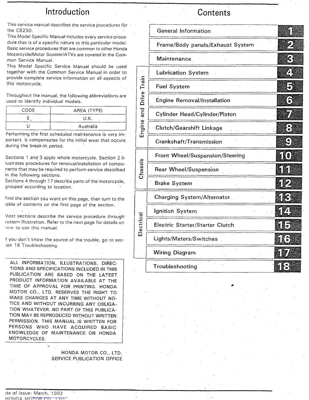
Introduction
This
service
manual describes
the
service procedures
fór
the
CB250.
This
Model
Specific Manual includes every service proce-
dure
that
is
of
a
specific
natura
to
this
particular
model.
Basic service procedures
that
are
common
to
other
Honda
Motorcycle/Motor
Scooter/ATVs
are
coveredin
the
Corn-
mon
Service
Manual.
This
Model
Specific
Service
Manual
should
be used
together
with
the
Common
Service
Manual
in order
to
provide
complete
service
information
on all
aspects
of
this
motorcycle,
Throughout
the
manual,
the
following
abbreviations
are
used to
identify
individual
rnodels.
CODE
AREA
(TYPE)
E
U.K.
U
Australia
Performing
the
first
scheduled
maintenance
is
very
im-
portant.
It
compensates
for
the
initial
wear
that
occurs
duríng
the
break-in
periodo .
Sections
1
and
3
applv
whole
motorcycle.
Sectíon
2 íl-
lustrates
procedures
for
removal/installation
of
cornpo-
nents
that
may
be required
to
perform
service
described
in
the
followinq
sections.
Sections
4
through
17 describe parts
of
the
motorcycle,
grouped
according
to
location.
Find
the
section
you
want
on
this
page,
then
turn
to
the
table
of
contents
on
the
first
page of the
section,
\I1ost
sections
describe
the
service
prccedure
throuqh
svstern
illustration.
Refer to
the
next
page
for
details
on
",OW
to use thís
manual.
f you
dont
know
the
source
of
the
trouble,
go
to
sec-
ion
18
Troubleshooting.
ALL
INFORMATION,
ILLUSTRATIONS,
DIREC-
TIONS AND SPECIFICATIONS INCLUDED IN THIS
PUBLlCATION
ARE BASED ON THE
LATEST
PRODUCT
INFORMATION
AVAILABLE
AT
THE
TIME
OF
APPROVAL
FOR PRINTING.
HONDA
MOTOR
CO.,
LTD.
RESERVES THE RIGHT TO
MAKE
CHANGES
AT
ANY
TIME
WITHOUT
NO-
TICE
AND
WITHOUT
INCURRING
ANY
OBLlGA-
TION
WHATEVER.
NO
PART
DF
THIS
PUBLlCA-
TION
MA
y BEREPRODUCED
WITHOUT
WRITTEN
PERMISSION. THIS
MANUAL
IS WRITTEN FOR
PERSONS
WHO"
HAVE
ACQUIRED
BASIC
KNOWLEDGE OF
MAINTENANCE
ON
HONDA
MOTORCYCLES,
HONDA
MOTOR
CO.,
LTD.
SERVICE PUBLlCATION OFFICE
rte
of
Issue:
March,
1992
Hnl\lnil.
~~nTnp
rn
I
Tn
e
ro
...
t-
(1)
>
"¡:
CI
-a
e
ro
.(1)
e
el
e
w
en
en
en
ro
..l:
U
ro
C)
"¡:
.....
C)
(1)
w
Contents
General
Information
Frame/B6dy
panels/Exhaust
System
Maintenance
Lubrication
System
Fuel
System
Engine
Removal/lnstallation
Cylinder
Head/Cylinder/Piston
Clutch/Gearshift
Linkage
Crankshaft/T
ransm
ission
Front
Wheel/Suspension/Steering
Rear
Wheel/Suspension
Brake
System
Charging
Systeml
Alternator
Ignition
System
Electric
Starter
IStarter
Clutch
Lights/Meters/Switches
Wiring
Diaqrarn
Troubleshooting
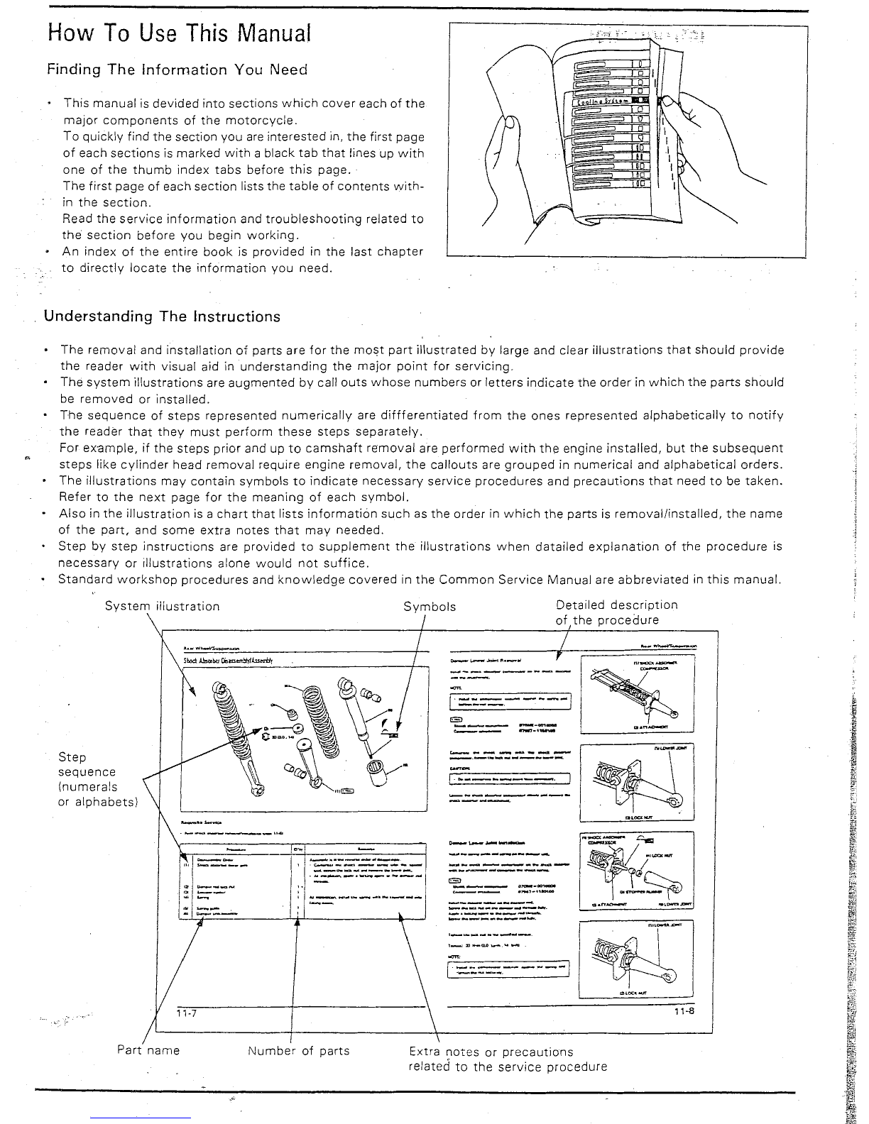
How
To
Use
This
Manual
Finding
The
Information You Need
This
manual
is
devided
into
sections
which
cover
each of
the
major
components
of
the
motorcycle.
To
quickly
find
the
section you are
interested
in,
the
first
page
of each
sections
is
marked
with
a
black
tab
that
lines up
with
one of
the
thumb
index
tabs
before
this
page.
The
first
page of each
section
lists the
table
of
contents
with-
in
the
section.
Read
the
service
information
and
troubleshooting
related
to
the
section
before
you
begin
working.
• An
index
of
the
entire
book
is
provided
in
the
last
chapter
to
directly
locate
the
information
you
need.
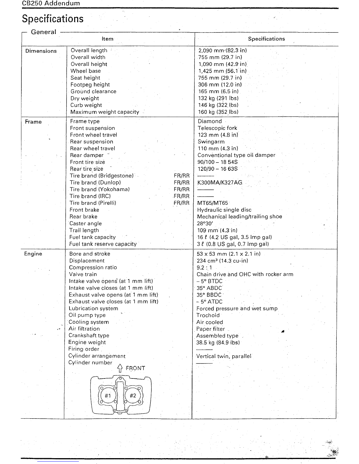
Understanding
The
Instructions
•
The
removal
and
installation
of
parts
are
for
the
rnost
part
illustrated
by large and
clear
illustr
ations
that
should
provide
the
reader
with
visual
aid in
understanding
the
major
point
for
servicing.
The
system
illustrations
are
augmented
by call
outs
whose
numbers
or
letters
indicate
the
order
in
which
the
parts
should
be
removed
or
installed.
The
sequence
of
steps
represented
numerically
are
diffferentiated
from
the
ones
represented
alphabetically
to
notify
the
reader
that
they
must
perform
these
steps
separately.
For ex-ample, if
the
steps
prior
and up
to
camshaft
rernoval
are
performed
with
the
engine
installed,
but
the
subsequent
steps
like
cylinder
head
removal
require
engine
removal,
the
callouts
are
grouped
in
numerical
and
alphabetical
orders.
The
illustrations
may
contain
symbols
to
indicate
necessary
service
procedures
and
precautions
that
need
to
be
taken.
Refer
to
the
next
page
for
the
meaning
of
each
symbol.
•
Also
in
the
illustration
is a
chart
that
lists
informatión
such
as
the
order
in
which
the
parts
is
removal/installed,
the
name
of
the
part.
and
some
extra
notes
that
may
needed.
Step
by
step
instructions
are
provided
to
supplement
the
illustrations
when
datailed
explanation
of
the
procedure
is
necessary
or
illustrations
alone
would
not
suffice.
Standard
workshop
procedures
and
knowledge
covered
in
the
Common
Service
Manual
are
abbreviated
in
this
manual.
11-8
r
Detailed
description
of
the
procedure
----
---
.,..,-
..
--
~--
..........
_--
-_.-
...
_------.
"----------
-----
------_-.
-_-..._-----_.
-.-._----_--.
---------.
----------
---------
I~-
1---
-1
I
~:::.::.::=:
- - - -]
Symbols
_
....
_-----
.e-...o_-..
_
.:.::
-::'-:'::"-::'::::-':::'-1
11-7
System
illustration
Step
sequence
(numerals
or
alphabets)
Part
name
Number
of
parts
Extra
notes
or
precautions
related
to
the
service
procedure
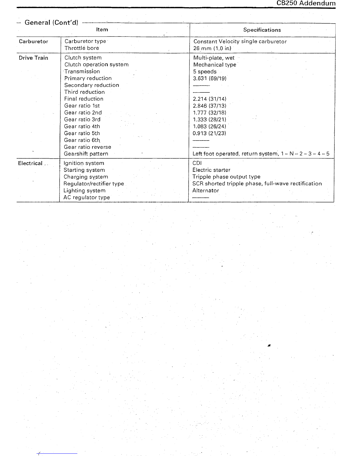
CB250
Addendum
Specifications
General
Item
Specifications
Dimensions
Frame
Engine
Overall
length
Overall
width
Overall
height
Wheel
base
Seat
height
Footpeg
height
Ground
clearance
Dry
weight
Curb
weight
Maximum
weight
capacíty
Frame
type
Front
suspensión
Front
wheel
travel
Rear
suspension
Rear
wheel
travel
Hear
damper
Front
tiresize
Rear
tire
size
Tire
brand
(Bridgestone)
Tirebrand
(Dunlop)
Tire
brand
(Yokohama)
Tire
brand
(IRC)
Tire
brand
(Pirelli)
Front
brake
Hear
brake
Caster
angle
Traillength
Fuel
tank
capacity
Fuel
tank
reserve
capacity
Bore
and
stroke
Displacement
Compression
ratio
Valve
train
Intake
valve
opens'
(att
mm
lift)
Intake
valve
closes (at 1
mm
lift)
Exhaust
valve
opens
(at 1
mm
lift)
Exhaust
valve
closes (at 1
mm
lift)
Lubrication
system
Oil
pump
type
ICo
olinp
system
.•- Ai r
fi/tration
Crankshaft
type
Engine
weight
Firing
order
"
Cylinder
arranqernent
Cylinder
number
i'I.
ti
FRONT
FR/RR
FR/RR
FR/RR
FR/RR
FR/RR
2,090
mm"{82;3
in)
755
mm
(29.7 in)
1,090
mm
(42.9"in)
1,425
mm
(56.1 in)
755
mm
(29.7 in)
306
mm
(12.0 in)
165
mm
(6.5 in)
132
kg(291
lbs)
146 kg
(322
lbs)
160
kg(352Ibs)
Diamond
Telescopic
fork
123
mm
(4.8
in)
Swingarm
110
mm
(4.3 in)
Conventiorial
type
oildamper
90/100 - 18
545
120/90 -
16635
K300MNK327
AG
MT65/MT65"
Hydraulicsingle
disc
Mechanical
leading/trailingshoe
28°30'
109
mm
(4.3 in)
16 e(4.2 U5
gal,
3.5
Imp
gal)
3e
(0.8
U5gal,
0.7
Imp
gal)
53 x 53
mm
(2.1 x 2.1 in)
234 cm" (14.3
cu-in)
9.2:
1
Chain
drive
and
OHC
with
rocker
arm
- 5° BTDC
"35°
ABDC
35°
BBDC'
- 5°
ATDC
Forced
pressureand
wetsurnp
Trochoid
Air
cooled
.
Paperfilter
"Assembled
type
38.5 kg (84.9Jbs)
Vertical
twin,
paral1el
-;~;
CB250
Addendum
G I (C
td)
-
enera
on
,
Item
Specifications
Carburetor
Carburetor
tvpe
Constant
Velocity
single
carburetor
Throttlé
bore
26mm
(1.0 in)
Drive
Train
Clutch
system
Multi-plate,
wet
Clutch
operation
system
Mechanical
type
Transmission
5
speeds
Primaryreduction
3.631 (69/19)
Secondary
reduction
---
Third
reduction
---
Final
reduction
2.214 (31/14)
Gear
ratio
1st 2.846 (37/13)
Gear
ratio
2nd
1.777 (32/18)
Gear
ratio
3rd
1.333 (28/21)
Gear
ratio
4th 1.083 (26/24)
Gear
ratio
5th 0.913 (21/23)
Gear
ratio
6th
---
Gear
ratio
reverse
---
Gearshift
pattern
Left
foot
operated,
return
system,
1- N - 2 - 3 - 4 - 5
Electrical
...
Ignition
system
CDI
Starting
system
Electric
starter
Charging
sy.stem
Tripple
phase
output
type
Regulator/rectifier
type
SCR
shorted
tripple
phase,
full-wave
rectification
Lighting
system
Alternator
AC
regulatortype
---
(

CB250
Addendum
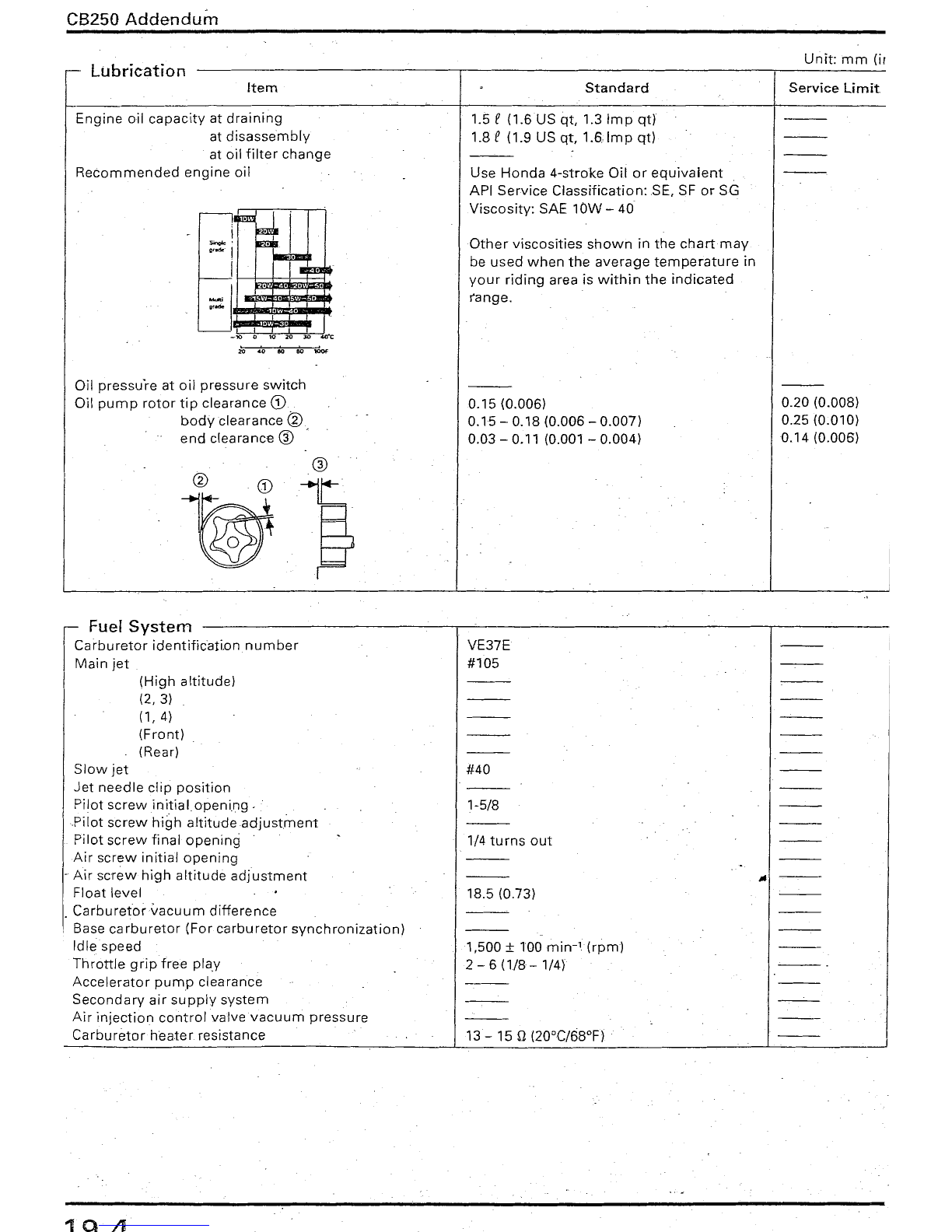
Lubrication
Unit:
mm
(in:
Item
Standard
Service
limit
Other
viscosities
shown
in
the
chartmay
be
used
when
the
average
temperature
in
your
riding
area is
within
the
indicated
range.
1.5 e
(1.6US
qt.
1.3
Imp
qt)
1.8 e(1.9 US
qt,
t.s.lmp
qt)
Use
Honda
4-stroke
Oil
or
equivalent
API
Service
Classífication:
SE,
SF
or
SG
Viscosity:
SAE
10W
- 40
01020304.O"C
I
5On%e
'
,,,
....
I
i
~Imm
Engine
oil
capacity
at
draining
at
disassembly
at
oil
filter
change
Recommended
engine
oil
20
40
lKl 80
Oil
pressure
at
oil
pressure
switch
Oil
pump
rotor
tip
clearance
CD
body
c1earance ®
end
clearance
®
0.15
(0.006)
0.15
-
0.18
(0.006 - 0.007)
0.03
- 0.11 (0.001 -
0.004)
0.20
(O.OOS)
0.25 (0.010)
0.14
(0.006)
r-
Fuel
System
Carburetor
identification
number
Main
jet
VE37E
#105
(High
altitude)
(2,3)
(1, 4)
(Front)
(Rear)
Slow
jet
Jet
needle
clip
position
Pilot
screwinitialopening.
Pilot
screw
high
attitudeadjustrnerrt
Pilot
screw
final
opening
Air
screw
initial
opening
.
Air
screw
high
altitude
adjustment
Float
level
Carburetorvacuurn
difference
!Base
carburetor
(For
carburetor
synchronization)
Idle
speed
Throttle
grip
free
play
Accelerator
pump
clearance
Secondary
air
supply
svstern
Air
injection
control
valve
vacuum
pressure
Carbur
etor
he
ater
resistance
#40
1-5/8
1/4 tu rns
out
lS.5
(0.73)
1,500 ±
TOO
min-'(rpm)
2 - 6
(l/S-
1/4)
I
1Q
.11
CB25D
Addendum
Lubrication
Item
Engine
oil
capacity
at
draining
at
disassembly
at
oil
filter
change
Recommended
engine
oil
20
40
80 80
Oil
pressure
at
oil
pressure
switch
Oil
pump
rotor
tip
clearance
CD
body
c1earance ®
end
clearance
CID
Standard
1.5 e
(1.6US
ot. 1.3
Imp
qt)
1.8 e(1.9 US
qt,
1.S.lmp
qt)
Use
Honda
4-stroke
Oil
or
equivalent
API
Service
Classification:
SE,
SF or SG
Viscosity:
SAE
10W
- 40
Other
viscosities
shown
in
the
chartmay
be
used
when
the
average
temperature
in
your
riding
area is
within
the
indicated
ranqe.
0.15
(0.006)
0.15
-
0.18
(O.OOS
-
0.007)
0.03 - 0.11 (0.001 -
0.004)
Unit:
mm
(ir
Service
Limit
0.20 (0.008)
0.25 (0.010)
0.14
(0.006)
~
Fuer
System
Carburetor
identification
number
Main
jet
(High
altitude)
(2,3)
(1, 4)
(Front)
(Re ar)
Slow
jet
Jet
needle
clip
position
Pilot
screwinitialopening.
Pilot
screw
high
altitudeadjustment
Pilot
screw
final
openinq
Air
screw
initial
opening
.
Air
screw
high
altitude
adjustment
Float
level
Carburetorvacuurn
difference
Base
carburetor
(For
carburetor
synchronization)
Idle
speed
Throttle
grip
free
play
Accelerator
pump
clearance
Secondary
air
supply
system
Air
injection
control
valvevacuum
pressure
Carburator
heater
resistance
1Q
Ji
VE37E
#105
#40
1-5/8
1/4
turns
out
18.5 (0.73)
1,500 ±100
rnirr
lIrprrrl
2 - 6
(1/8-
1/4)
13 - 15 n(20°C/68°F)
CB25D
Addendun
Unit:
mm
(in
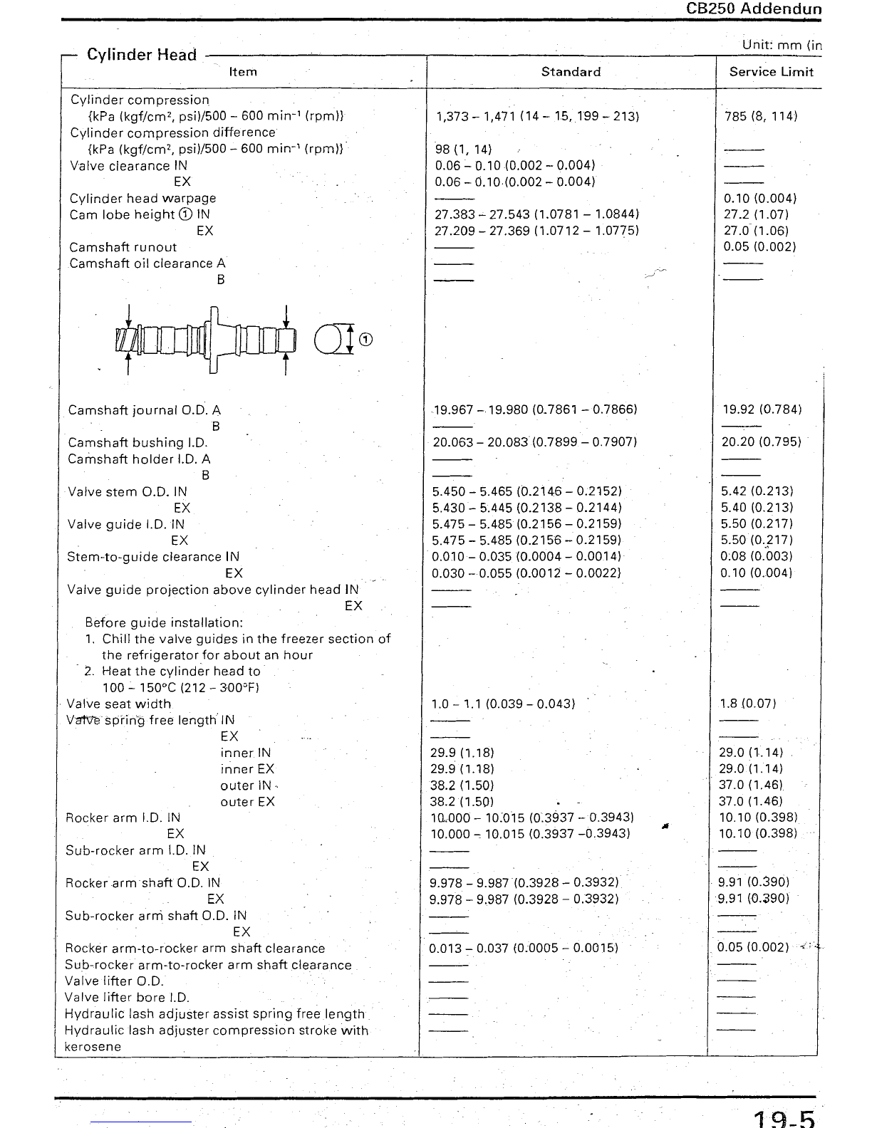
Cylinder
Heacl
-----~~----_._--------------___,__------:.-
Item
Standard
Service
Limit
Cylinder
com
pression
{kPa
(kgf/cm
2,psi)/500 - 600
min-
1(rprnl)
Cylinder
compression
difference
{kPa
(kgf/cm
2,psi)/500 - 600
mirr
'
(rprnl}
Valve
clearance
IN
EX
Cylinder
head
warpage
Cam
lobe
height
CD
IN
EX
Camshaft
runout
Camshaft
oil
clearance
A
B
1,373 - 1,471 (14 -
15,199
- 213)
98
(1,14)
0.06 -
0.10(0.002
-0.004)
0.06 -0.10·(0.002 -0.004)
27.383..c 27.543 (1.0781 - 1.0844)
27.209 -27.369 (1.0712 -1.0775)
785 (8, 114)
0.10 (0.004)
27.2 (1.07)
27.0(1.06)
0.05 (0.002)
OJCD
Camshaft
journal
0.0.
A
B
Camshaft
bushing
1.0.
Carnshaft
holder
1.0. A
B
Va/ve
stem
0.0.
IN
EX
Valve
guide
1.0. IN
EX
Stem-to-guide
clearance IN
EX
Valve
guide
pr
ojection
aboye
cylinder
head
IN
EX
Before
guide
installation:
1.
Chill
the
valve
guides
in
the
freezer
section
of
the
refrigeratorfor
about
an
hour
- 2.
Heat
the
cylinder
head
to
100 - 150°C (212 - 300°F)
.Valve
seat
width
Vert\re
sprin'g
free
length
IN
EX
inner
IN
inner
EX
outer
IN
-.
outerEX
Rocker
arm
1.0. IN
EX
Sub-rocker
arm
1.0. IN
EX
RockerarmshaftO.D.
IN
EX
Sub-rocker
arrn
shaft
0.0.
IN
EX
Rocker
arrn-to-rocker
arrn
shaft
clearance
Sub-rocker
arrn-to-rocker
arrn
shaft
clearance
Valve
lifter
0.0.
Valve
lifter
bore
1.0.
Hydraulic
lash
adjuster
assist
spring
freelength
Hydrauliclash
adjuster
compression
stroke
with
kerosene
19.967
-19.980
(0_7861 - 0.7866)
20.063 -20.083 (0.7899 -0.7907)
5.450 - 5.465 (0.2146 -0.2152)
5.430 - 5.445 (0.2138 -0.2144)
5.475 - 5.485 (0.2156 -0.2159)
5.475 - 5.485 (0.2156 -0.2159)
0.010-
0.035
(0.0004
-0.0014)
0.030
-0.055
(0.0012 -0.0022)
1.0 - 1.1 (0.039 - 0.043)
29.9 (1.18)
29.9 (1.18)
38.2 (1.50)
38.2(1.50)
1
Q.OOO
-10:015 (0.3937
-0.3943)
10.000.., 10.015 (0.3937
-0.3943)
9.978 -
9.987(0.3928
-0.3932)
9.978 - 9.987 (0.3928 -0.3932)
0.013:-
0.037 lO.0005 -0.0015)
19.92 (0.784)
20.20 (0.795)
5.42 (0.213)
5.40 (0.213)
5.50 (0.217)
5.50 (0..
;217)
0:08 (0.003)
0.10 (0.004)
1.8 (0.07)
29.0
(l.14)
29.0(1.14)
37.0 (1.46)
37.0 (1.46)
10.10 (0.398)
10.10 (0.398)
. 9.91 (0.390)
9.91 (0.390)
0.05 (0.002) ..
19-5

CB25ü
Addendum
Cvlinder/Piston
Item
Cylinder
I.D.
out
of
round
taper
warpage
Piston
mark
direction
Pisto
n O.D. (O)
Piston
O.D.
measurement
point
(H)
Piston
pin
hole
I.D. (d)
(d)
Cylinder-to-piston
clearance
Pisten
pin
O.D.
Piston-to-piston
pin
clearancé
Connectinq
rod-to-piston
pin
clearance
Top
ring-to-ring
groove
clearance
Second
ring-to-ring
groove
c1earance
Top
ring
end
gap
Second
ring
end
gap
Oil
ring
(side
rail)
end
gap
Top
ring
mark
Second
ring
mark
-Crankshaft
Connecting
rod
small
end I.D.
Connecting
rod
bigendside
clearancs
radial clé
arance
-
Crankshah
runout
(at
both
ends)
G)
(at
bearing
holder)
@
bG)
39.5
mm
(1.56 in)
U .
IJ
l'9.5
mm
(0.37 in)
Crank
pin
oil
clearance
Crank
pin
bearing
selection
Main
journal
oil
clearance
Main
journal
bearing
selsction
Standard
53.000
-
53.010
(2.0866
-
2.0870)
"IN"
mark
facing
toward
the
intake
side
52.970
-
52.990
(2.0854
-
2.0862)
10
mm
(0.4 in)
from
the
bottom
15.002
-
15.008
(0.5906 -
0.5909)
0.010
-
0.040
(0.0004
-
0.0016)
14:994
-
15.000
(0.5903 -
0.5906)
0.002
-
0.014(0.0001
-
0.0006)
0.016
-
0.040
(0;0006 -
0.0016)
0.015
-
0.040
(0.0006 -
0.0016)
0.015
-0.040(0.0006
-
0.0016)
0.15 -
0.30
(0.006 -0.012) .
0.30
-0.45 (0.012 -0.018)
0.2 - 0.7 (0,01 - O.03)
"N".mark
side
facing
up
"N"
markside
facing
up
15.016
-
15.034
{0.59 J2 -
0.5919)
0.10-0.40
(0.004-0.016)
0,004
-
0.012
(0.0002 -
0.0005)
.""
Unit:
mm
(in)
Service
Limit
53.10
(2.091)
0.05 (0.002)
0.05 (0.002)
0.05(0.002)
52.90
(2.083)
15.05 (0.593)
0.10
(0.004)
14.98
(0.590)
0.07 (0.003)
0.10
(0.004)
0.10
(0.004)
0.10 (0.004)
0.45(0.018)
0.60
(0.024)
0.90
(0.036)
15.08 (0.594)
0.6 (0;02)
0.05
(0.002)
0.03
(0.001)
0.05
(0.002)
..
-Kickstarter
--------'--------'-------,-----------~----~-,------
Kickstarterpinion
gear
I.D.
Kickstarter
spindle
O.D.
Kickstarter
id le
gear
I.D.
Countershah
O.D. at
kickstarter
id le
gear
Kickstarter
idle
gearbushing
O.D.
I.D.
19-6

Transrnrssion
Item
Transmission
gear
I.D. M5
Cl
C4
Transmission
gear
bushing
O.D. Cl
Transmission
gear
bushing
I.D.
el
Gear-to-bushing
clearance
at
Cl
gear
Mainshaft
O.D. at M5
gear
at c1utch
outer
guide
G)
Countershaft
O.D. at Cl
gear
at C4
gear
Gear-to-shaft
clearance
at M5
gear
at C4
gear
Gear
bush
ing-to-shaftclearance
al
Cl
gear
Shift fork
claw
thickness
L
C
R
Shift
fork I.D. L
C
R
Shift
fork
shaft
O.D. L
C
R
Shift
drum
O.D.
Standard
20.020
-20.041 (0.7882 -0.7890)
20.020
-20.041
(0.7882
-0.7890)
20.020
-20.041 (0.7882 -0.7890)
19.979-
20.006
(0.7866
-0.7874)
16.516
-
16.534
(0.6502 -0.6509)
0.020
-0.062 (0.0008 -0.0024)
19.959
-19.980
(0.7858
-0.7866)
19.959
-19.980
(0.7858 -0.7866)
16.446
-16.484
(0.6475
-0.6490)
19.959
-19.980
(0.7858
-0.7866)
0.040
-0.082 (0.0016 -0.0032)
0.040 -0.082 (0.0016
-0.0032)
0.032
-0.068 (0.0013 -0.0027)
4.93 -
5.00(0.194
-
0.197)
4.93 -5.00 (0.194 -
0.197)
4.93 - 5.00 (0.194
-0.197)
12.000 -
12.018
(0.4724
-0.4731)
12.000
-12.018
(0.4724
-0.4731)
12.000 -12.018
(0.4724-0.4731)
"'"19 :976"';
11.994
(0.4715
-0.4722)
11.976 -
11.994
(0.4715
-0.4722)
11.976
-
11.994
(0.4715
-0.4722).
CB250
Addendum
Unit:
mm
(in)
Servica
Umit
20.08
(0.791)
20.08
(0.791)
20.08
(0.791)
19.93(0.785)
16.58
(0.653)
0.10(0.004)
19.91 (0.784)
19.91 (0.784)
16.41 (0,646)
19.91 (0.784)
0.10(0.004)
0.10 (0.004)
0.10 (0.004)
4.80 (0.189)
4.80 (0.189)
4.80 (0.189)
12.05 (0.474)
12.05 (0.474)
12.05 (0.474)
11.93 (0.470)
11.93 (0.470)
11.93 (0.470)
19-7

Unit:
mm
(in)
r-
Cfutch
System
Item
Standard
Service
Limit
Clutch
lever
free
play
10 - 20 (3/8
~
3/4)
---
Recornrnended
clutch
fluid
--- ---
Clutch
master
cylinder
I.D.
---
---
Clutch
master
piston
O.D.
--- ---
Clutch
outer
I.D.
26.000
-
26.012
(1.0236
-
1.0241)
26.04
(1.025)
Clutch
outer
guide
O.D.
25.959
-
25.980
(1.0220 -
1.0228)
25.90
(1.020)
I.D.
20.000
-
20.021
(0.7874
-
0.7882)
20.05
(0.789)
Mainshaft
O.D. at
ciutch
outer
guide
--- ---
Clutch
spring
free
heigJ;ot:"
---
---
Clutch
spring
free
length
37.~
(1.49)
36.0
(1.42)
Clutch
disc
thickness
2.8
- 2.9 (0.11 - 0.15)
2.6
(0.10)
Clutch
disc
thickness
A
--- ---
B
--- ---
Clutch
plate
warpage
---
0.20
(0.008)
Centrifugal
clutch
drum
I.D.
---
---
bushing
O.D.
---
---
Centrifugal
clutch
center
guide
I.D.
---
---
0.0.
---
---
Centrifugal
clutch
center
guide
collar.heiqht
---
---
Centrifugal
clutch
weight
lining
thickness
---
---
Centrifugal
clutch
spring
free
length
---
---
Clutch
lining
thickness
---
---
Crankshaft
O.D. at
clutch
center
---
~.
---
~
CoolingSystem
Coolant
capacito
y_
(Radiato.r and
engine)
(Reserve
tank)
Radiator
cap
relief
pressure
Thermostat
begin
to
open
I
Thermostat
fully
open
.
Thermostat
valva
lift
-
Drive
Train
Recommended
final
drive
oil
Final
drive
gear
oil
capacity
at
disassembly
at
draining
Final
drive
gear
backlash
Final
drive
gear
backlash
difference
between
measurement
Ring
gear-to-stop
pin
clearance (A)
Stop
pin
shim
Ring
gear
spacer
Pinion
spacer
Final
drive
gear
assembly
preload
Output
gear
backlash
Output
gear
I.D.
Output
gear
bushing
0:0.
I.D.
Output
drive
shaftO.D.
Output
geardamper
spring
free
length
Output
shaft
adjustment
shirn
Countershaft
drive
shaft
adjustment
shim
19-8

CB250
Addendum
Unit:
mm
(in)
-
Wheels/Tires
Item
Standard
Service
Limit
Minimum
tire
thread
depth
(FR)
---
1.5 (0.06) I
(RR)
---
2.0(0.08)
I
Cold
tire
pressure
Up 1'090 kg (200 lb)
load
(FR) 200
kPa(2.00
kgf/cm
2,29 psi)
---
Up
1'090 kg (200 lb)
load
(RR) 200 kPa (2.00 kqf/crn", 29 psi)
---
Up
1'0
maximum
weight
capacity
(FR) 200
kPa(2.00
kgf/cm
2,29 psi)
---
Up
1'0
maximum
weight
capacity
(RR) 200 kPa (2.00
kgf/cm
2,29 psi)
---
,
Front
and
rear
axle
runout
0.2 (0.01)
Front
and
rear
wheel
rirn
runout
(Radial)
---
2.0 (0.08)
(Axial)
---
2.0 (0.08)
Front
wheel
hub-to-rirn
distance
,
---
---
Front
wheel
hub
standard
surface
---
----
Rear
wheef
hub-to-rim
distance
---
---
I
Rear
wheel
hub
standard
surface
I
---
---
,
Wheel
balance
weight
(Front)
---
609
(2.1
oz)max.
(Rear)
---
609
(2.1
oz)
max.
Orive
cha in
slack
20 - 30 (3/4 - 1-1/4)
---
,
Orive
chain
size/link
(010) 520VC.6-106LE
---
\
(RK)
520MO-Z9-106LE
---
r-r-'
Front
Suspension
Fork
spri
ng
free
length
Fork
spring
free
length
A
8
Fork
spring
direction
Fork
tube
runout
Recommended
fork
oil
Fork
oil
level
Fork
oil
level
(R)
(U
Fork
oil
capacity
Fork
oil
capacity
(R)
{U
_
Fork
air
pressure
Steering
bearing
preload
59.7 (2.35)
488.7 (19.24)
Tightly
wound
coil
facing
down
Forkfluid
162
(6.4)
150
cm"
(5.1 US oz, 5.3
Impoz)
0.1 - 0.15
kgf-m
58 (2.3)
479 (18.86)
0.2 (0.01)
r-r-
'Rear
Suspension
Shock
absorber
spring
free
length
Shock
absorber
spring
free
leriqth
(A)
(8)
Oamper
gas
pressure
Oamper
compressed
gas
Oaniper
rod
compressed
force
at 10
mm
(0.4 in)
compressed
Oamper
driUing
point
Shock
absorber
spring
installed
length
(Standard)
(Adjustable
range)
Shock
absorberspríng
adjuster
standard
position
2nd
groove
Shock
absorber
spring
direction
Recommended
shock
absorber
oil
Shock
absorber
oil
capacity
air
pressure
19-9

CB250
Addendum
Unit:
mm
(in)
Brakes
---------------....-------~-----------,....-----~-.-:.
Item
Standard
Service
Limit
Front
brake
fluid
brake
lever
free
play
brake
pad
wear
indicator
DOT
3 or
DOT
4
10 - 20 (3/8 -
314)
.To
the
groove
CD
CD
brake
disc
thickness
brake
disc
runout
master
cylinder
1.0.
master
piston
0.0.
caliper
cylinder
1.0.
caliper
cvlinder
1.0.
(Upper).
(Lower)
caliper
piston
0.0.
caliper
piston
0.0.
(Upper)
(Lower)
brake
drum
1.0.
brake
Iining
thickness
Rear
brake
fluid
brake
pedal
height
brake
pedal
free
play
brake
pad
wear
indicator
..
If0í
~
J01?"
,':1
/
,')<~~~j
brake
disc
thickness
brake
disc
runout
master
cylinder
1.0.
master
piston
0.0.
caliper
cylinder
1.0.
caliper
piston
0.0.
brake
drum
1.0.
brake
lining
thickness
4.0 (O.16)
11.0 - 11.043 (0.4331 - 0.4348)
10.957
-10.984
(0.4314 -0.4324)
27.000 -27.050 (1.0630 - 1.0650)
26.918 -26.968 (1.0598 -1.0617)
20 - 30 (3/4 -1-1/4)
130 (5.1)
4.0 (O.16)
3.5 (0.14)
0.30 (0.012)
11.05 (0.435)
10.95 (0.431)
27.06 (1.065)
26.91 (1.059)
131 (5.2)
2.0 (0.08)
r-r-
Battery/Charging
System
Alternator
chargingcoil
resistance
(At
20°C/68°F)
Regulator/rectifier
regulated
voltaqe/arnperaqe'
Battery
capacity
Battery
specific
gravity
(Fullv
charging)
(Needs
charging)
Battery
chargíng
rate
(Normal)
(Quick)
Battery
voltage
(Fully
charged
20°C!68°F)
(Needs
charging
20°C/68°F)
Alternator
lightingcoil
resistance (At
20°C/68°F)
. AC
regulator
regulated
voltage
(With
analog
type)
(With
digital
type)
0.2 - 0.6 n
13.5
-14.0
V/1 A
12 V - 6 Ah
0.6A/10h
3
A/1.0
h
13-13.2V
Below
12.3 V
CB250
Addendum
i!
,\
Unit:
mm
(in)
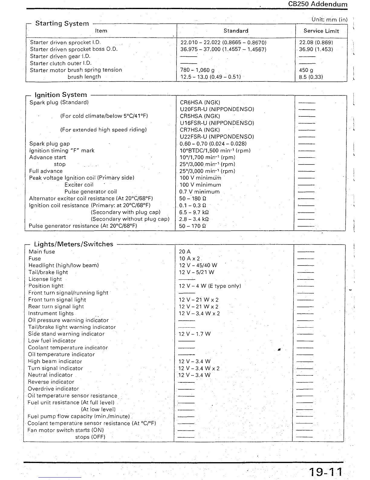
s
St
tO
r-
ar
mg
ystem
Item
Standard
Service
Limit
Starter
driven
sprocket
1.0.
22.010-
22.022
(0.8665
-
0.8670)
22.08
(0.869)
Starter
driven
sprocket
boss
0.0.
36.975
-
37.000
(1.4557 -
1.4567)
,
36.90
(1.453)
Starter
driven
gear
'1.0.
'---
---
Starter
clutch
outer
1.0.
---
---
Starter
motor
brush
spring
tension
780
-1,060
9450 9
brush
length
12.5
-13.0 (0.49 -0.51) 8.5 (0.33)
-
Ignition
System
Spark
plug
(Standard)
(For
cold
climate/below
5°C/41°F)
(For
extended
high
speed
riding)
Spark
plug
gap
Ignition
timing
"F"
mark
Advance
start
stop
Full
advance
Peak
voltage
Ignition
coilIf'rirnarv
side)
Exciter
coil
PuIse
generator
coil
Alternator
exciter
coil
resistance
(At
20°C/68°F)
Ignition
coil
resistance
(Prirnarv: at 20°C/68°F)
(Secondary
with
plug
cap)
(Secondary
without
plug
cap)
Pulse
generator
resistance
(At
20°C/68°F)
CR6HSA
(NGK)
U20FSR-U
(NIPPONOENSO)
CR5HSA
(NGK)
U16FSR-U
(NIPPONDENSO)
CR7HSA
(NGK)
U22FSR-U
(NIPPONDENSO)
0.60
-
0.70
(0.024 -
0.028)
10
0BTDC/1,500min-'
(rpm)
10°/1,700
min-'
(rpm)
25°/3,000min-
1
(rpm)
25°/3,000
min-'
(rprn)
100 V rninimurn
100 V
minimum
0.7V
mínimum
50-1800
0.1-0.30
6.5 - 9.7 kO
2.8
- 3.4 kO
50 - 170 O
Lights/Meters/Switches
Main
fuse
Fuse
Headlight
(high/low
beam)
Tail/brake
light
License
light
Position
light
Front
turn
signal/running
light
Front
turn
signallight
Rear
turn
signal
light
Instrument
lights
'.
Oil
pressure
warning
indicator
Tail/brake
light
warning
indicator
Side
stand
warning
indicator
Low
fuel
indicator
Co
olant
temperature
indicator
Oil
temperature
indicator
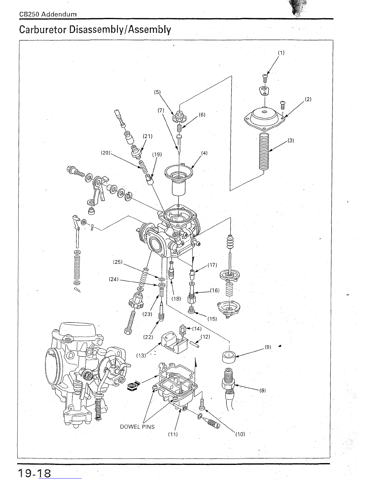
High
beam
indicator
Tu
rnsig
n
ali
ndicator
Neutral
indicator
Reverse
indicator
Overdrive
indicator
Oil
temperature
sensor
resistance
Fuel
uriit
resistance
(At
fu"
level)
(At
low
level)
Fuel
pumpflow
capacity
(min./minute)
Coolant
temperatúre
sensor
resistance
(AtOC¡OFj
Fan
motor
switch
starts
(ON)
stops
(OFF)
20A
10 Ax2
12V-45/40W
12 V - 5/21 W
12 V - 4 W (E
type
only)
12V-21Wx2
12V-21
Wx2
12 V - 3.4 W
x2
12V-l.7W
12V-3.4W
12 V - 3.4 Wx 2
12 V - 3.4 W
19-11

CB250
Addendum
Torque
Values
r-r-:
Standard
Fastener
Type
Torque
Fastener
Type
Tarque
.
N'm
[kgf-m,
Ib-ft)
N'm
(kgf'm,
Ib-ft)
5
mm
hex
bolt
and
nut
5 (0.5, 3.6) 5
mm
screw
4 (0.4, 2.9)
6
mm
hex
bolt
and
nut
10 (1.0, 7) 6
mm
screw
9 (0.9, 6.5)
8
mm
hex
bolt
and
nut
22 (2,2, 16) 6
mm
flange
bolt
(8
mm
head)
9 (0.9, 6.5)
10
mm
hex
bolt
and
nut
34(3.5,
25} 6
mm
flange
bolt
(10
mm
head)
and 12 (1.2, 9)
12
mm
hex
bolt
and
nut
54 (5.5, 40)
nut
8
mm
flange
bolt
and
nut
26 (2.7, 20)
1°
mm
flange
bolt
and nut 39 (4.0, 29)
Torque
specifications
listed
below
are
for
important
fasteners.
Others
should
be
tightened
to
standard
torque
values
listed
aboye.
NOTE
1.·
Apply
sealant
to
the
threads.
2.
Applya
locking
agent
to
the
threads.
3.
Apply
molybdenum
disulfide
oil
to
thethreads
and
flange
surface.
4.
Left
hand
threads.
5. Stake.
6.
Apply
oil
to
the
threads
and
flange
surface.
7.
Apply
clean
engine
oil
to
the
O-ringo
8.
Torque
wrench
scale
reading
usinga
special
tool.
9.
Apply
grease
to
the
threads
and
flange
surface.
10. UBS
bolt.
11.U-nut.
12.
Alock
bolt.
Do
not
reuse.
E
r--
ngme
I
Item
O'tv
Thread
dia.
Tarque
Remarks
(mm)
N'm
(kqf-rn,
Ib-ft)
.,
Lubrication
System:
Oil
pump
mounting
screw
3610 (1.0, 7)
Cylinder
Head/Cvlinder:
Spark
plug
210
12(1.2,9)
Va/ve
adjusting
lock
nut
I
45¡
10(1.0,7)
Cylinder
head/camshaft
holder
nut
88I23 (2.3, 17)
Cvlinder
head
bolt
3 6 i12 (1.2, 9)
Cam
sprocket
bolt
2 7 20 (2.0, 14)
Note
2
Cylinder
h~d
cover
bolt
26,10 (1.0, 7)
Clutch/Gearshift
Linkage:
Clutch
lifter
bolt
46
12(1.2,9)
Clutch
center
locknut
116 74
(7.6,55)
Note
5, 6
Shift
drum
stopper
arm
bol!
.I16
12(1.2,9)
Gearshift
return
spring
pin
18
25(2.5,18)
Note
2
Primary
drive
gear
lock
nut
116 53 (5.4, 39)
Crankcase/Cran
kshaft:
A
Drive
sprocket
bolt
2 6
12(1.2,9)
Oil
drain
bolt
112 25 (2.5, 18)
Crankshaft
mounting
bolt
5823 (2.3, 17)
Crankshaft
mounting
nut 1612 (1.2, 9)
Oil
passage
plate
mounting
screw
36
10(1.0,7)
Note
2
Starter
Clutch/
Alternatar:
Flywheel
bolt
110 59 (6.0, 43)
Starter
clutch
mounting
screw
369 (0.9, 6.5)
Note
2, 5
Stator
mountíng
screw
35I6 (0.6, 4.3)
Stator
wire
clamp
screw
15I6 (0.6, 4.3)
Pulse
generator
mounting
screw
2610 (1.0, 7)
Starter
motor
terminal
nut
166 (0.6, 4.3)
19-12

CB250
Addendum
F
r-r-'
rame
.
Thread
día.
Torque
,i
ltern
Q'ty
Remarks
Lo.
(mm)
N·m
(kqf-rn,
Ib-ft)
Front
Suspension:
L
Steering
stem
nut
1 22
74
(7.5, 54)
Steering
stem
adjustment
nut
1 22 3(0.3, 2.2)
;~
Handlebar
holder
bolt
4o' 824
(2.4,17)
Fork
top
bridge
pinch
nut
2822 (2.2, 16)
Note
11
Fork
bottom
bridge
pínch
bolt
2 8 24 (2.4, 17) 1'-
Steering
lock
mounting
bott
2 6 9(0.9, 6.5)
Note
2
Fork
cap
2 27 23 (2.3, 17)
Fork
socket
bolt
2820
(2.0,14)
Note
2'1
i
Rear
Suspension:
'-
Swingarm
pivot
nut
114 59 (6.0, 43)
Note
11
Rear
shock
absorber
lower
mounting
bolt
210 42
(4.3,31)
Wheels:
Front
axle
nut
114 59
(6.0,43)
Note
11
~
Rear
axle
nut
114 59
(6.0,43)
Note
11
Brake
arm
torque
link
bolt
2822
(2.2,16)
~
Driven
sprocket
nut
410 44 (4.5, 33)
Note
11
Brake
system:
Pad
pin
plug
1 8 3
(0.3,2.2)
"i
Pad
pin
1818 (1.8, 13) ". o'
Caliper
pin
bolt
(bracket
side)
1 8 13
(1.3,9)
Note
2
t-
(caliperside)
1 8 23 (2.3, 17)
Note
2
Caliper
bleed
valve
166
(0.6,4.3)
Frorit
caliper
mounting
bolt
30
(3.1, 22) I
210 I
Brake
disc
bolt
4 8 42
(4.3,31)
"-
Master
cylinder
reservoir
cap
screvv 2I42(0.2, 1.4)
Brake
hose
oil
bolt
2la
34
(3.5, 25) J
Brake
lever
pivot
nut
166(0.6, 4.3) l1
o,
....
Rearbrake
arm
pinch
bolt
1610 (1:0, 7)
Other
Fasteners:
L
Engine
rear
mounting
bolt
2 10 83 (8.5,
61)
Exhaust
pipe
joint
nut
46I14
(1.4,10)
Side
stand
switch
mounting
bolt
1 6 29
(3.0,22)
Note
12
~J
Side
stand
bracket
bolt
2i836 (3.7, 27)
,ti
CB250
Addendum
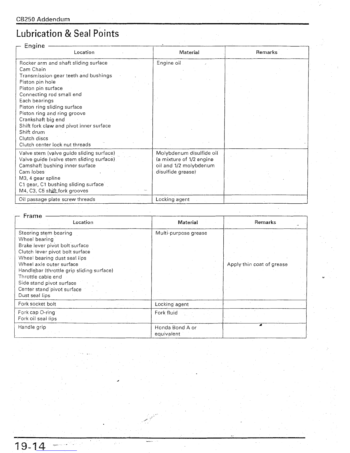
Lubrication
&
Seal
Points
E
~
ngme
Location
Material
Remarks
Rocker
arm
and
shaft
sliding
surface
Engine
oil
Cam
Chain
Transmission
gear
teeth
and
bushings
Piston
pin
hole
Piston
pin
surface
Connecting
rod
small
end
Each
bearings
Piston
ringsliding
surface
Piston
ring
and
ring
groove
Crankshaft
big
end
Shift
fork
claw
and
pivot
inner
surface
Shift
drum
Clutch
discs
Clutch
center
lock
nut
threads
Valve
stem
(valve
guide
sliding
surface)
Molybdenum
disulfide
oil
Valve
guide
(valve
stem
slidinq
surface)
(a
mixture
of
1/2
engine
Camshaft
bushing
inner
surface
oil
and
1/2
molybdenum
Cam
lo bes
disulfide
grease)
M3,
4
gear
spline
Cl
gear,
Cl
bushing
sliding
surface
M4, C3, C5 shift.fork
grooves
Oil
passage
plate
screw
threads
..
Locking
agent
F
~
rarne
Location
Material
Remarks
..
Steering
stern
bearing
Multi-purpose
grease
Wheel
bearing
.
Brake
lever
pivot
boltsurface
Clutch
lever
pivot
bolt
surface
Wheel
bearing
dust
seallips
Wheel
axle
outer
surface
Applythin
coat
of
grease
Handlebar
(throttle
grip
sliding
surface)
Throttle
cable
end
Side
stand
pivot
surface
Center
standpivot
surface
Dust
seal
lips
Fork
socket
bolt
Locking
agent
Forkcap
O-ring
Fork
fluid
Fork
oil
seallips
Handle
grip
Honda
Bond
A
or
"-
equivalent
./
19-14
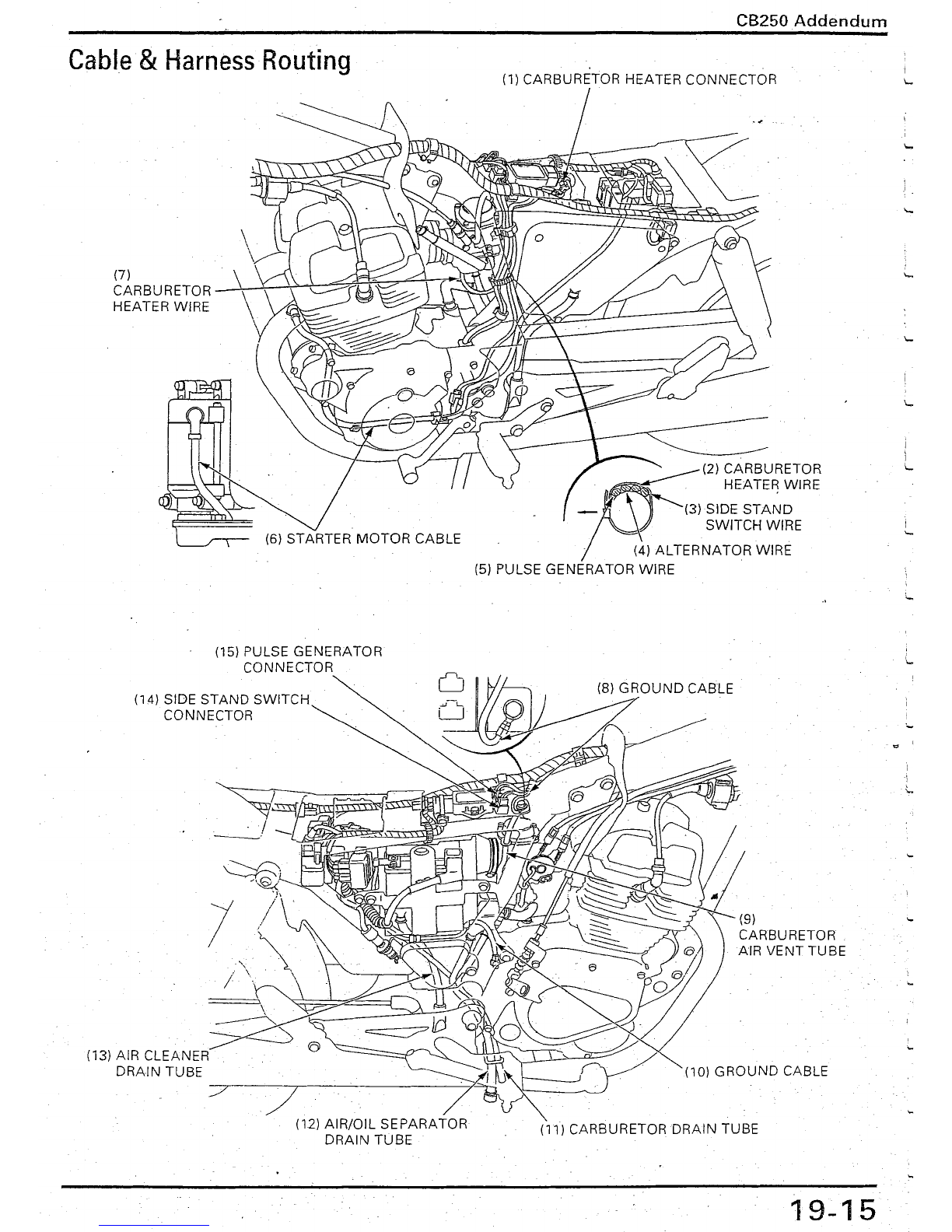
Cable
&
Harness
Routing
(7)
CARBURETOR
HEATER WIRE
(15) PULSE GENERATOR
CONNECTOR
(14) SIDE
STAND
SWITCH
CONNECTOR
CB250
Addendum
(1) CARBURETOR HEATER CONNECTOR
___
(2) CARBURETOR
~
HEATER WIRE
r
Q
~
(
3
}
S
I
D
E
STA~D
'=-V
.
SWITCH
WIRE
. (4)
ALTERNATOR
WIRE
(5) PULSE GENERATOR WIRE
/
(/
(9)
CARBURETOR
AIR VENT
TUBE
(10)
GROUND
CABLE
19-15
j
i
'-
I
'-
L
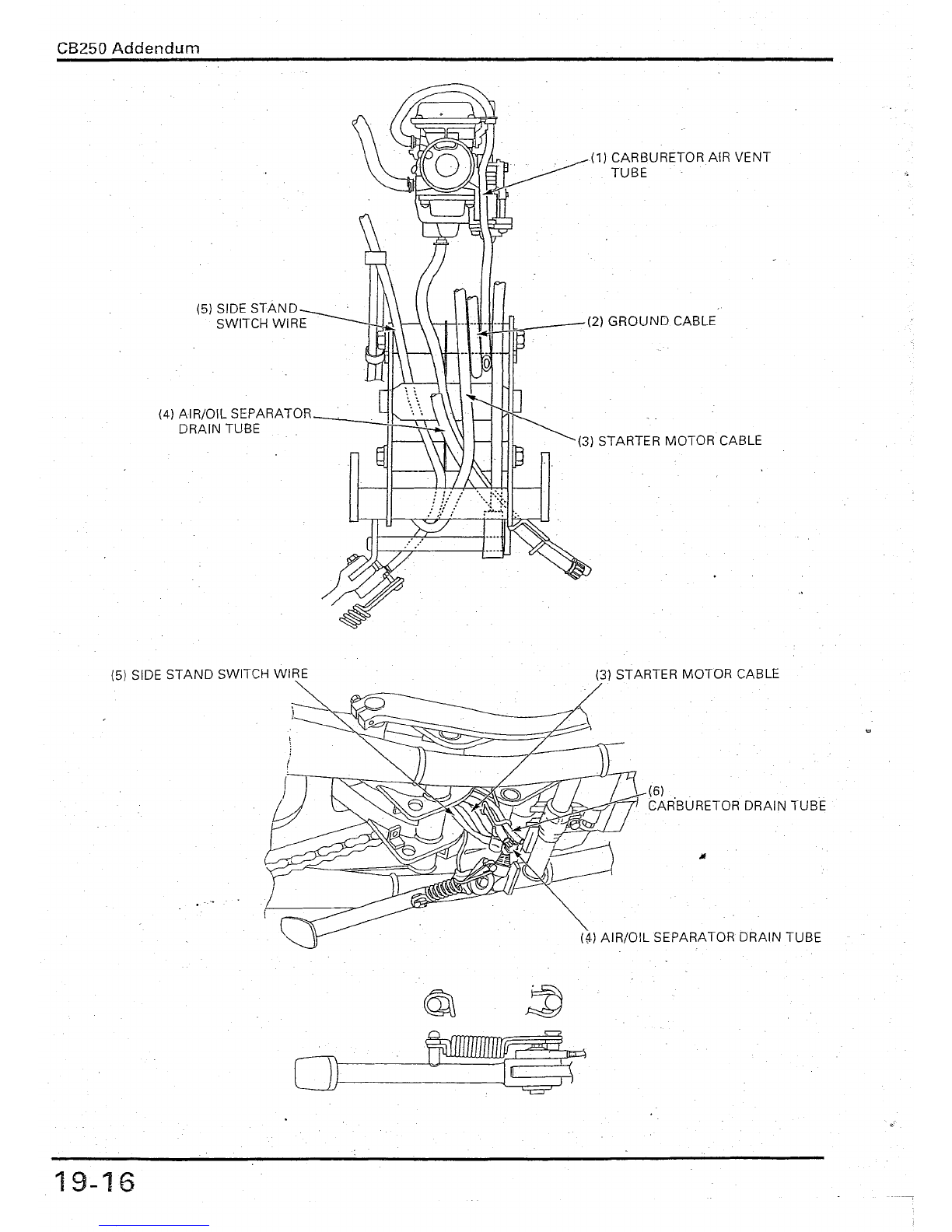
CB25D
Addendum
(3) STARTER MOTOR CABLE
(5) SIDE
STAND
SWITCH WIRE (3) STARTER MOTOR CABLE
(6)
CAR'BURETOR DRAIN TUBE
(M AIR/OIL SEPARATOR DRAIN TUBE
~
~
0\--------1
----l.,)...~-~
o'g1r
19-16

CBZ50
Addendum
Carburetor
Removal/lnstallation
Gasoline
is
extremely
flammable
and is
explosive
under
certain
conditions.
Work
in
well
ventilated
area.
Smoking
or
allow
flames
or
sparksinthe
working
area
or
wheregasolineis
stored
can
cause
a
fire
or
explosion.
NOTE
Before
removal,
turn
the
fuel
valve
OFF.
Route
the
tubes
and
wires
properly
(page
19-15).
Requisite
Service
I
'-
Rear
fairing
removal/installation
(page
2-3)
Fuel
tank
removal/installation
(page
2-4)
Carburetor
draíning
Procedure
I
Q'ty·
Remarks
Removal
Order
lnstallation
is in
the
reverseorder
of
removal
(1)
Carburetor
heater
2P
connector
1
'"
(2)
Wire
barid/Clurnp
1/1
(3)
Clutch
cable
1
(4)
Th
rottle
cables
2
(5)
Choke
cable
1
(6)
Drain
tube
1
(7)
Carburetor
mounting
nut
2
(8)
Connecting
tube
band
screw
1
Onlyloosen.
(9)
Carburetor
assembly
1
..
(10)
O-ring
1
(11)
Gasket
~.-
1
19-17
CB25ü
Addendum
bly/Assembly
..
sem
__
Carburetor
Dlsas
.
(3)
(1)
I
.
-(8)
1(9) A
~
(4)
(11 )
19-18
Table of contents


/LC Owner's service manual")


