FOREWORD
This manual contains an introductory
description
on
the SUZUKI SV1000S and procedures for its
inspection/service and overhaul of its main compo-
nents
.
Other information considered as generally known is
not included
.
Read the GENERAL INFORMATION section to
familiarize yourself with the motorcycle and its main-
tenance
. Use this section as well as other sections
to use as a guide for proper inspection and service
.
This manual will help you know the motorcycle bet-
ter so that you can assure your customers of fast
and reliable service
.
* This manual has been prepared on the basis
of the latest specifications at the time of publi-
cation
. If modifications have been made since
then, differences may exist between the con-
tent of this manual and the actual motorcycle
.
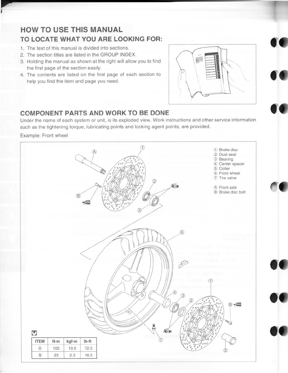
* Illustrations in this manual are used to show
the basic principles of operation and work
procedures
. They may not represent the
actual motorcycle exactly in detail
.
* This manual is written for persons who have
enough knowledge, skills and tools, including
special tools, for servicing SUZUKI motorcy-
cles
. If you do not have the proper knowledge
and tools, ask your authorized SUZUKI
motorcycle dealer to help you
.
may
not
be
able
to
properly
perform
the
services described in this manual
.
Improper repair may result in injury to the
mechanic and may render the motorcycle
unsafe for the rider and passenger
.
SUZUKI MOTOR CORPORATION
© COPYRIGHT SUZUKI MOTOR CORPORATION 2003
GROUP /NDE
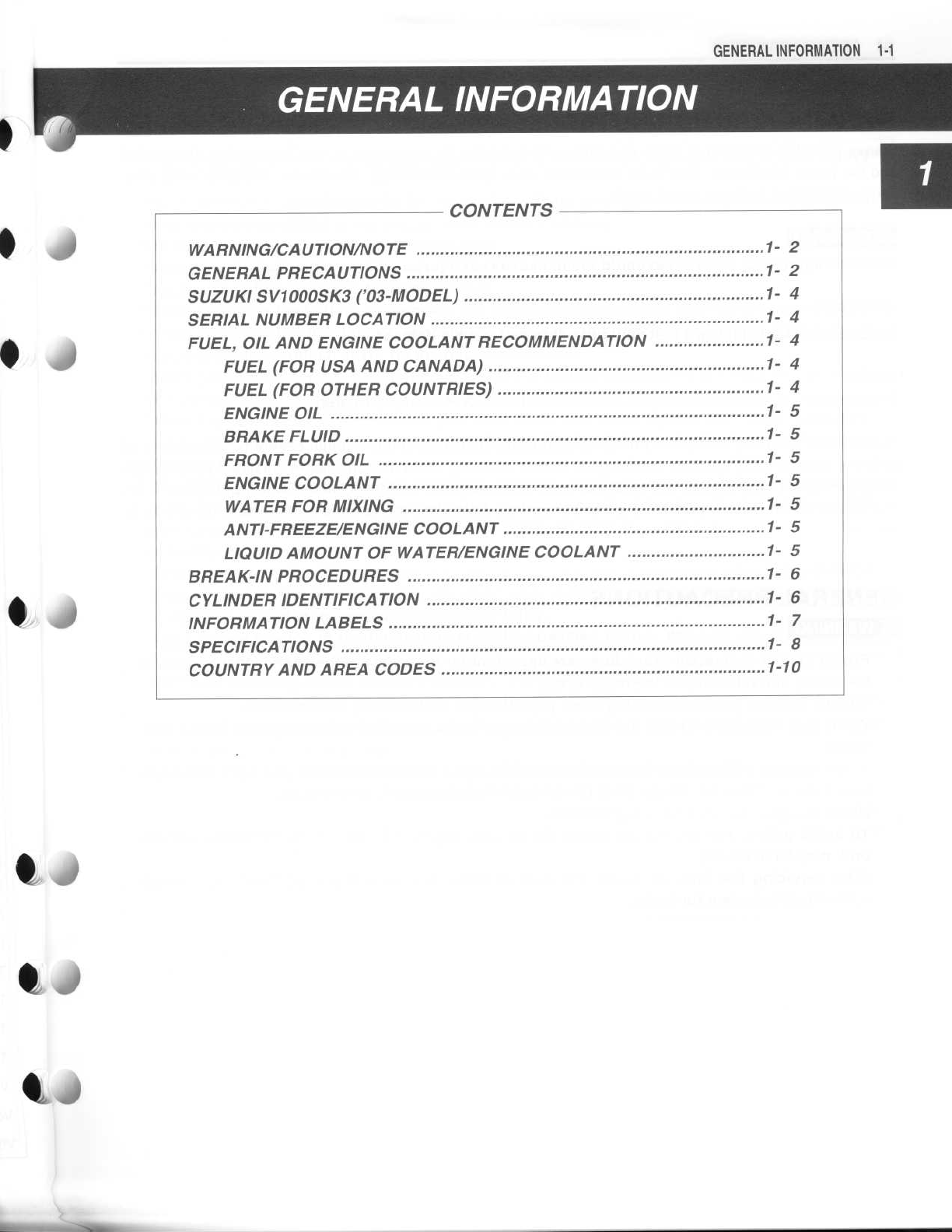
GENERAL INFORMATION
PERIODIC MAINTENANCE
ENGINE
FI SYSTEM
4
COOLING AND LUBRICATION
SYSTEM
CHASSIS
ELECTRICAL SYSTEM
E
SERVICING INFORMATION
EMISSION CONTROL
INFORMATION
WIRING DIAGRAM
A
WARNING
Inexperienced
mechanics
or
mechanics
without the proper tools
and
equipment


 Supplementary service manual")