TECNICOMAR ECOmar S Series User manual
INSTRUCTIONS FOR THE INSTALLATION,
USE AND MAINTENANCE OF
TECNICOMAR SYSTEM FOR SEWAGE WATER TREATMENT
MODEL: ECOmar 20 S; 32 S; 45 S; 70 S; 145 S.
S
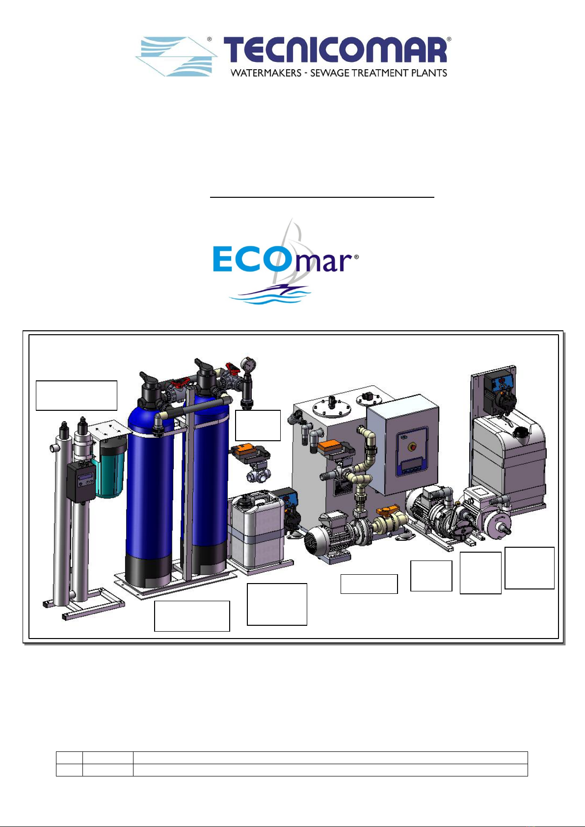
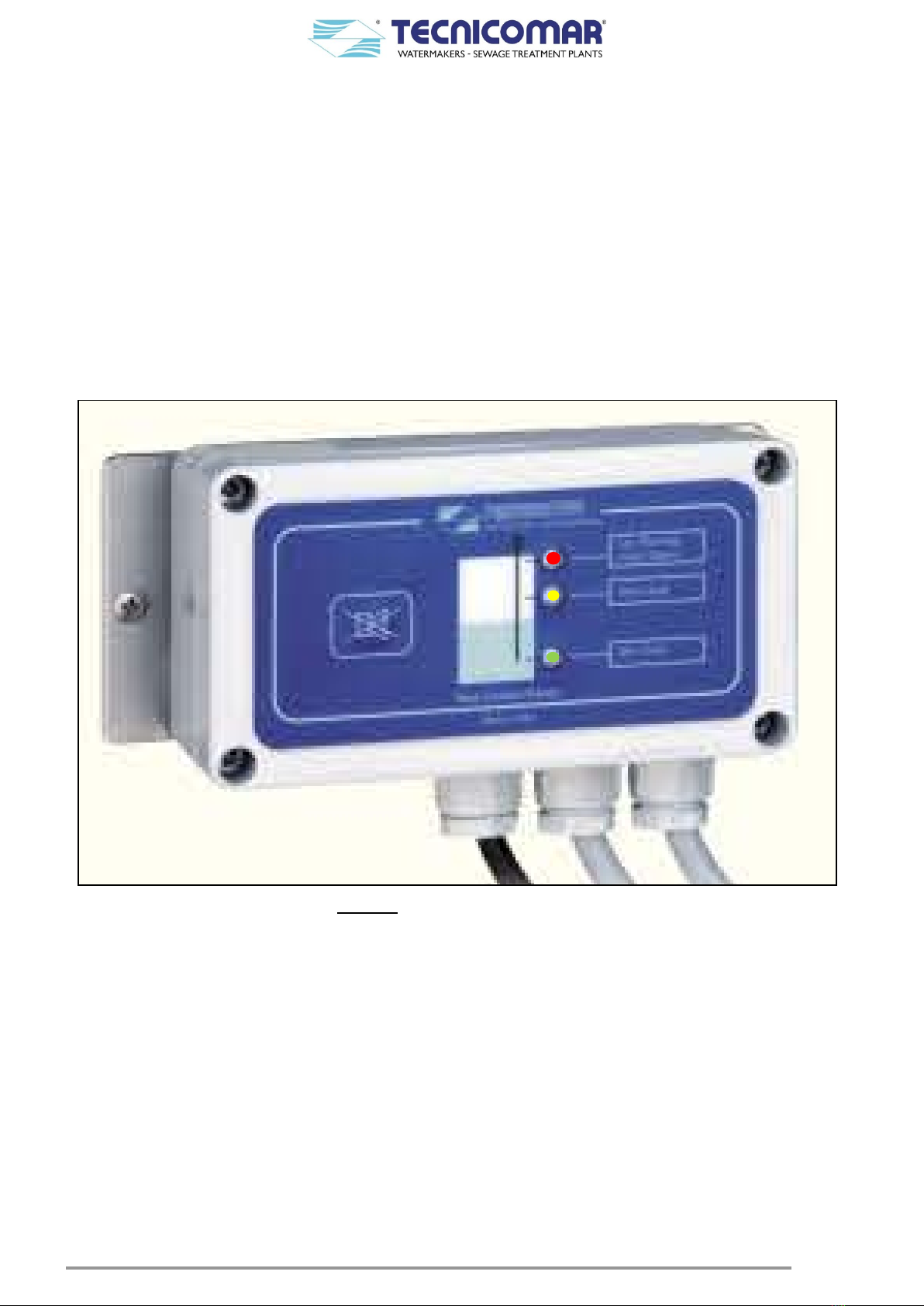
Image for illustration purposes only
Rev.
Date
Main content revisions
00
10.02.2019
Main Unit
H
2
O
2
Dosing
System
Sea
Water
Pump
Filling
Pump
H
2
O
2
Dosing
System
ECOFLOC
Dosing
System
Multimedia
Filter Station
UV Sterilization
Unit
Sludge
Valve
2
Dear Customer,
We would like to thank you for choosing a TECNICOMAR system to treat the sewage water.
All TECNICOMAR equipments are designed by expert technicians and manufactured with care for all its aspects and in
respect of the EU Directives for the machinery (safety) 89/392 and later modifications.
Before using the unit you are kindly requested to read carefully this manual as integral part of the equipment since the
respect of the instructions here quoted assures the performance and the operator safety.
WARNING!
TECNICOMAR S.P.A. declines any and all liability for failure to observe the safety and accident prevention
standards described in this manual, for damage due to the improper use of the equipment and for modifying it
without the authorisation of Tecnicomar S.P.A.
Signs used throughout the Manual
Warning
These instructions should be followed carefully to operate the equipment correctly.
Danger
These instructions should be followed carefully to avoid damage to the equipment or to the operator.
Note or Information
The notes contain important information and useful hints to run the unit.
If not specified otherwise, letters & numbers used in the text refer to the functional diagram shown in the drawings situated at
the end of this Manual.
* * * * * * * * * * * * * * * * * * * * * * * * * * * * * * * * * * * * * * * * * * * * * * * * * *
This Manual is intellectual property of Tecnicomar S.P.A. Any reproduction of contents or drawings – unless authorized
by Tecnicomar S.P.A. – is not permitted and will be prosecuted.

3
TABLE OF CONTENTS
1INTRODUCTION.............................................................................................................................................................5
2STORAGE PRIOR TO UNPACKING AND PACKAGING CONTENT........................................................................5
2.1 Storage Prior to Unpacking...........................................................................................................................................5
2.2 Unpacking.....................................................................................................................................................................5
2.3 Checking Packaging Content........................................................................................................................................5
3MARKING OF PRUDOCT...............................................................................................................................................6
4PLACARD.........................................................................................................................................................................6
5TREATMENT CAPACITY..............................................................................................................................................6
6SYSTEM DESCRIPTION.................................................................................................................................................7
6.1 Management system of the level signals from the collecting tank sensors...................................................................9
6.1.1 Control box for level probe ...............................................................................................................................11
7SAFETY INSTRUCTIONS ............................................................................................................................................13
7.1 Important Safety Information......................................................................................................................................13
7.2 Instructions and Warnings ..........................................................................................................................................13
7.3 CE Declaration of Compliance ...................................................................................................................................15
7.4 Targets of the Manual .................................................................................................................................................16
7.5 Safety Instructions and Prevention..............................................................................................................................16
7.5.1 Generalities.......................................................................................................................................................16
7.5.2 Noise..................................................................................................................................................................16
7.5.3 Protections.........................................................................................................................................................17
7.5.4 General Instructions for Safety Use ..................................................................................................................17
7.6 Before Turning on.......................................................................................................................................................17
7.6.1 Checks before Turning On.................................................................................................................................17
7.6.2 Useful Advice.....................................................................................................................................................17
7.7 Danger Informations...................................................................................................................................................18
7.8 Fire and Explosion Prevention....................................................................................................................................19
7.9 Cuttings Prevention.....................................................................................................................................................19
7.10 Fluid Recommendations .............................................................................................................................................19
7.10.1 Hydrogen Peroxide (H2O2) solution..................................................................................................................19
7.10.2 ECOFLOC solution...........................................................................................................................................19
8INSTALLATION ............................................................................................................................................................20
8.1 Components to be supplied by Owner ........................................................................................................................20
8.2 Qualification of the Installation Crew.........................................................................................................................20
8.3 Fixing the skid.............................................................................................................................................................20
8.4 Installation of the level sensor for Sludge Tank..........................................................................................................21
8.5 Main unit plumbing connections.................................................................................................................................21
8.5.1 Installing the H2O2dosing line..........................................................................................................................21
8.5.2 Installing the ECOFLOC dosing line................................................................................................................21
8.5.3 Installing the filling line ....................................................................................................................................21
8.5.4 Installing the seawater line ...............................................................................................................................21
8.5.5 Installing the air relief.......................................................................................................................................22
8.5.6 Installing the Main Unit and Sludge Discharge Valve (V2) interconnection line.............................................22
8.6 Loose parts installation ...............................................................................................................................................22
8.6.1 Installing Filling section....................................................................................................................................22
8.6.1.1 Installing the Level Probe on the collecting tank.....................................................................................22
8.6.1.2 Installing filling pump..............................................................................................................................24
8.6.1.2.1 Installation of the suction pipe of the filling pump .............................................................................25
8.6.2 Installing sea water pump .................................................................................................................................25
8.6.3 Installing H2O2dosing system...........................................................................................................................26
8.6.3.1 Transfer of H2O2solution ........................................................................................................................26
8.6.4 Additional Unit..................................................................................................................................................27
8.6.4.1 Installing ECOFLOC dosing system........................................................................................................27
8.6.4.1.1 Transfer of ECOFLOC solution..........................................................................................................27
8.6.4.2 Installing the Sludge Discharge Valve (V2) ............................................................................................28
8.6.4.3 Installing the Multimedia Filter Station...................................................................................................28
8.6.4.4 Installing the U.V. Sterilizer ....................................................................................................................28
8.7 Outboard discharge line ..............................................................................................................................................29
8.8 Electrical connections.................................................................................................................................................29
8.8.1 Main Control Box..............................................................................................................................................29
8.8.2 H2O2 DOSING SYSTEM ..................................................................................................................................30
8.8.3 LEVEL PROBE CONTROL BOX......................................................................................................................30
8.8.4 REMOTE CONTROL (OPTIONAL).................................................................................................................. 31
9PCB CONTROL PANEL – Functional Description........................................................................................................32
9.1 Main page ...................................................................................................................................................................32

4
9.1.1 Programming the parameters of the Electronic board PRO14/02 for ECOmar S............................................32
9.2 Automatic mode..........................................................................................................................................................34
9.3 Manual mode ..............................................................................................................................................................35
9.4 Alarms Description.....................................................................................................................................................36
9.4.1 Filling Alarm.....................................................................................................................................................36
9.4.2 Seawater Alarm.................................................................................................................................................37
9.4.3 Sludge Tank Overflow Alarm ............................................................................................................................38
9.4.4 Tank Overflow Alarm ........................................................................................................................................38
9.4.5 Overload Alarm.................................................................................................................................................38
9.4.6 High Pressure Alarm.........................................................................................................................................39
9.5 Remote control for ECOmar S - model: CDMAR2 (optional) ...................................................................................40
9.6Remote control for ECOmar S - model: PC link (optional)........................................................................................41
9.7 Remote control for ECOmar - model: Touch screen (optional)..................................................................................41
10 FIRST START UP PROCEDURE..................................................................................................................................42
10.1 Start-up Procedure ......................................................................................................................................................42
10.2 Shutdown Procedure...................................................................................................................................................43
11 ROUTINE OPERATION ................................................................................................................................................43
12 SPECIAL PROCEDURES ..............................................................................................................................................44
12.1 Overboard (Untreated Sewage) Discharge procedure.................................................................................................44
12.1.1 Macerating/Discharge pumps performance curves...........................................................................................45
12.2 Emptying the Treatment Tank procedure (in case of Tank Overflow Alarm) ............................................................49
12.3 Winterizing procedure.................................................................................................................................................49
12.3.1 Washing the treatment tank...............................................................................................................................51
12.3.2 Washing the Level Sensor of the treatment tank................................................................................................51
13 COMMON PROBLEMS AND TROUBLESHOOTING................................................................................................52
13.1 Troubleshooting Table................................................................................................................................................52
13.1.1 Manual opening activation for motorized valves ..............................................................................................57
14 MAINTENANCE INSTRUCTIONS ..............................................................................................................................59
14.1 Ordinary Maintenance.................................................................................................................................................59
14.1.1 H2O2 Dosing system.........................................................................................................................................59
14.1.2 ECOFLOC Dosing system.................................................................................................................................59
14.1.3 Multimedia Filter Station ..................................................................................................................................60
14.1.4 U.V. Sterilizing System ......................................................................................................................................60
14.2 Extraordinary Maintenance.........................................................................................................................................61
14.2.1 Collecting Tank level probes instructions .........................................................................................................61
14.2.2 Filling pump instructions ..................................................................................................................................61
14.2.3 Treatment Tank Level probes instructions ........................................................................................................62
14.2.4 Pressure switch instructions..............................................................................................................................62
14.2.5 Dosing Systems (H2O2& ECOFLOC) instructions...........................................................................................62
14.2.6 Seawater pump instructions ..............................................................................................................................62
14.2.7 Macerating pump instructions...........................................................................................................................63
14.2.8 Three-Way Motorized Valves (V1&V2) instructions.........................................................................................63
14.2.9 Multimedia Filter Station instructions...............................................................................................................63
14.2.10 U.V. Sterilizing System instructions ..................................................................................................................64
14.3 System Settings...........................................................................................................................................................64
14.3.1 H2O2Dosing pump setting................................................................................................................................. 64
14.3.2 ECOFLOC Dosing pump setting.......................................................................................................................65
14.3.3 Display Contrast Calibration............................................................................................................................65
14.4 MAINTENANCE PLAN FOR SEWAGE TREATMENT PLANT ECOMAR S......................................................66
15 TECHNICAL SPECIFICATIONS..................................................................................................................................69
15.1 ECOmar 20 S – Data Sheet......................................................................................................................................... 69
15.2 ECOmar 32 S – Data Sheet......................................................................................................................................... 70
15.3 ECOmar 45 S – Data Sheet......................................................................................................................................... 71
15.4 ECOmar 70 S – Data Sheet......................................................................................................................................... 72
15.5 ECOmar 145 S – Data Sheet.......................................................................................................................................73
16 SPARE PARTS LISTS....................................................................................................................................................74
17 WARRANTY FOR TECNICOMAR EQUIPMENTS....................................................................................................80
17.1 WARRANTY CLAIM................................................................................................................................................80
17.1.1 ECOmar S - WARRANTY REGISTRATION CARD...........................................................................................81
ANNEXES................................................................................................................................................................................86

5
1INTRODUCTION
The system is able to treat the on board sewage water as to make it suitable to be discharged directly into the sea, in accordance
with the international standard (IMO-MARPOL regulation – MEPC 227).
The unit does not need to be run by any operator, who has only to start up the unit in automatic mode. The ECOmar S plant is
a batch functioning system that treat a fixed quantity of sewage at each operating cycle. Each cycle starts with the loading of a
set quantity of sewage water from the on board collecting tank (your supply). After loading, the sewage is diluted with clean
seawater and pre-set quantities of Hydrogen Peroxide (H2O2) and ECOFLOC Flocculants are added. Finally the sewage is
macerated and mixed for a fixed period of time, after which it is made to rest for a further fixed period of time. During these
steps, lasting some minutes, the chemical-physical reactions inside the system disinfect the water, reduce the dimensions of
sediments and separate the cleared water from the sludge. At this point, the cleared water pass throughout a multimedia filter
station and an U.V. sterilizer and finally it is discharged outboard into the sea, according to the International Rules (IMO-
MARPOL regulation – MEPC 227). In the final step of the operation cycle the system discharges the residual sludge into the
on board sludge tank (your supply).
The automatic mode functioning is continuous in that the unit is able to start-up automatically a sewage treatment cycle every
time the set quantity of stored sewage; relative to the collecting tank level (Max Level) set to start-up the cycle; is reached
inside the on board collecting tank (your supply).
Each operating cycle lasts about 22-25 minutes. For the sewage quantities treated by the plant refer to the TREATMENT
CAPACITY section.
2STORAGE PRIOR TO UNPACKING AND PACKAGING CONTENT
2.1 Storage Prior to Unpacking
⇒Do not store in direct sunlight.
⇒Do not freeze (see SPECIAL PROCEDURES section).
⇒Do not store above 50°C (122°F).
⇒Store only on base with arrows up.
2.2 Unpacking
a) Open the wood case, if any, being careful to do not hit the protruding parts of the components, such as fittings or pipes,
hose-barbs, flange, etc.
b) Use caution in moving the STP plant and all its loose parts with a forklift or a pallet truck after it is removed from the
shipping crate. Place wood or other material onto the metal forks of the forklift (pallet truck) which can damage the powder
coating on the underside of the skid.
c) Always remember that, despite being accurately packaged and protected, the supply contains light bulbs and quartz tubes:
this means that the entire system must be considered as fragile material and handled as such.
2.3 Checking Packaging Content
After unpacking the Sewage Treatment Plant (STP), check all the parts for any damage. Claims for any missing or damaged
materials must be made immediately to Tecnicomar authorized dealer or Tecnicomar headquarters
In the package there are usually the following components:
•ECOmar S STP main unit, complete with Treatment tank, Macerating pump, Motorized Discharge Valve (V1), PCB control
panel, Multilevel sensors and Nr.4 Anti-vibration dampers (installed on the Main ECOmar S frame).
•Nr.1 Sea water pump*.
•Nr.1†or Nr.2‡filling pumps*.
•Nr.1†or Nr.2‡level probes complete with relative level probe control box (or junction box)*.
•Nr.1 H2O2Dosing system complete with dosing pump and tank*.
•Nr.1 ECOFLOC Dosing system complete with dosing pump and tank*§.
•Nr.1 Sludge Discharge Valve (V2)*§.
•Nr.1 Multimedia Filter Station, complete with the proper quantity of Zeolite and Quartzite*§.
•Nr.1 U.V. Sterilizer*§, complete with U.V. lamps.
•Installation Kit: Nr.3†or Nr.4‡anti-syphon valves set; Nr.1 diaphragm manual pump; hose for dosing pump; and clamps.
•Optional devices, such as a remote control.
*Supplied as loose part.
†If the plant is supplied for one tank control.
‡If the plant is supplied for two tanks control.
§Supplied on request inside a common customizable Additional Skid.
6
3MARKING OF PRUDOCT
A Nameplate is affixed on the front of the unit, showing:
•Manufacturer information
•EC mark stamp
•Model
•Serial number
•Year of construction
•Voltage
•Hydraulic loading Fig. 3-1 - Nameplate Fig. 3-2 – Mark label
A wheel mark label, attached close to the nameplate, with the identification of the Notified Body and followed by the year in
which the mark is affixed.
4PLACARD
ATTENTION
THE INSTALLATION PROCEDURES EXPOSE THE INSTALLER TO HIGH VOLTAGE AND ELECTRICAL
SHOCK HAZARD. ONLY ATTEMPT INSTALLATION IF YOU ARE A QUALIFIED TECHNICIAN AND
ONLY IF SURROUNDING CONDITIONS ARE SAFE.
DO NOT USE ANY FILTERS ALONG ALL THE AIR RELIEF LINE.
MAKE SURE ALL ANTI-SIPHON VALVES ARE PROPERLY INSTALLED.
CHECK ALL HYDRAULIC PIPES/HOSES ARE PROPERLY FIXED.
CHECK ALL ELECTRICAL CABLES ARE PROPERLY WIRED.
CHECK ROTATION OF ALL MOTORS ACCORDING TO THEIR ARROWS.
USE A CIRCUIT BREAKER IN ORDER TO AVOID OVERLOAD. ITS SIZE DEPENDS ON ELECTRICAL
CONSUMPTION OF THE UNIT.
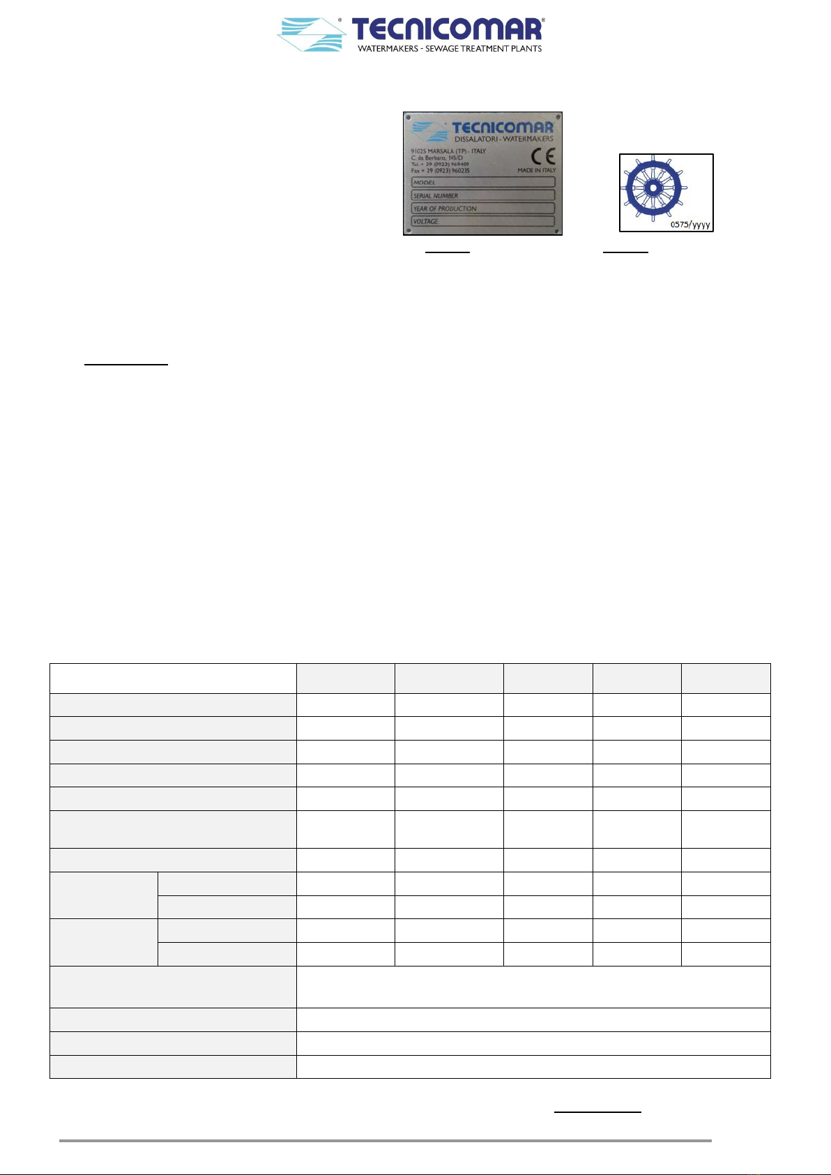
5TREATMENT CAPACITY
Marine Sanitation Device ECOmar20 S ECOmar 32 S ECOmar 45 S ECOmar 70 S ECOmar 145 S
Average capacity per day (lt.) 1500 2400 3375 5250 10875
Peak capacity per day (lt.)* 2000 3200 4500 7000 14500
Average capacity per hour (lt.) 62.5 100 140.625 218.75 453.125
Peak capacity per hour (lt.) 83.3 133.3 187.5 291.67 604.17
Sewage capacity treated per cycle (lt.) 33.75 52.8 66.5 107.865 241.5
Seawater / brackish water / fresh water load
per cycle (lt.) *** 24.3 38.016 47.88 71.91 124.2
Total volume per cycle (lt.) 58.05 90.816 114.38 179.775 365.7
Persons**, if
passenger ships Without vacuum plant 8 14 19 30 63
With vacuum plant 10 17 24 37 78
Persons**, if
other ships Without vacuum plant 11 17 25 38 80
With vacuum plant 14 23 33 51 107
Condition of heel up to
(max angle of pitch and roll) 22.5°
Range of environmental temperature 0°C ÷ 55°C
Humidity 95%
Salinity 55000 ppm
*System running 24 hours per day.
**Indicative maximum persons number, at peak treatment capacity per day (system running 24h/24h). Ask to Tecnicomar S.P.A. for a proper plant sizing.
***Designed to operate in salt, brackish and fresh water.
7
6SYSTEM DESCRIPTION
The ECOmar S STP can be supplied with two different configuration: 1 Tank Control or 2 Tanks Control.
The main differences between the two configurations are the number of the supplied filling pumps (1 or 2); the number of the
supplied anti-syphon valve set; the number of the supplied level probes; the number of the supplied level probe control boxes;
the dosing systems arrangement and the main control box arrangement.
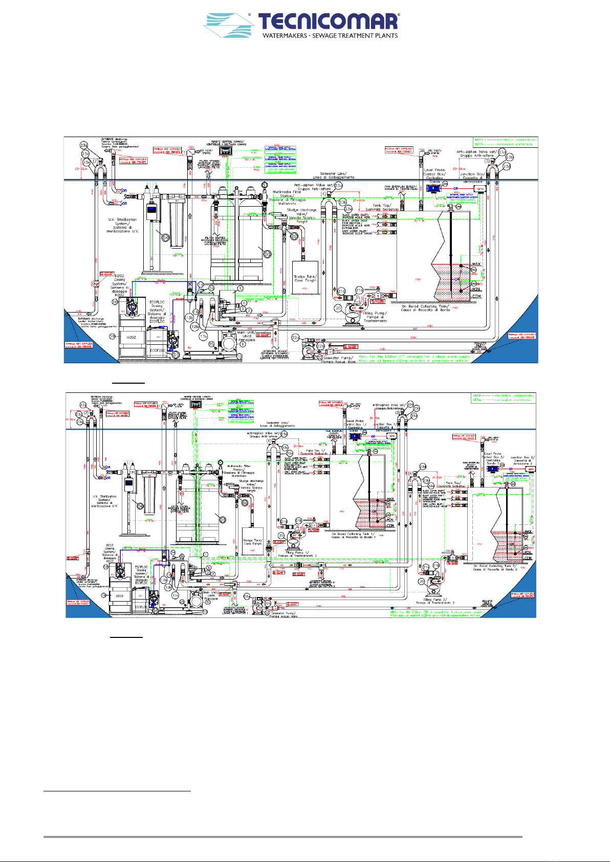
The diagrams below show a functional installation scheme of the plant with its main components for both configurations.
Fig. 6-1 - Functional installation scheme – 1 Tank Control - (see also annexed drawing)
Fig. 6-2 - Functional installation scheme – 2 Tanks Control - (see also annexed drawing)
As shown in the diagrams above, the system is composed by:
1. AMain Unit Skid made by:
1.1. A tank (Treatment Tank) made of PP (polypropylene) or SS (stainless steel)*, where the sewage water is treated;
1.2. A pump (Macerator or Macerating Pump) to treat and discharge the treated water;
1.3. A motorized Discharge Valve (V1) to divert the treated water to the sludge discharge valve (V2) inlet or back to the
treatment tank;
1.4. Level probes†, installed on the treatment tank, for the tank level monitoring;
1.5. A pressure sensor (Pressure Switch)‡to protect the treatment tank from overpressure;
1.6. A PCB control panel (Main Control Box) with motor protections, contactors, microprocessor, touch pad and liquid
crystal back-lighted display.
*For the ECOmar 70 S and 145 S; the treatment tank is available only in SS (stainless steel).
†Nr.1 Multi-point Ball Level Switch for ECOmar 20 S – 32 S – 45 S – 70 S – 145 S.
‡Only for the STP supplied with the treatment tank in PP (polypropylene).

8
Loose parts
2. An Additional Unit*made by:
2.1. Nr.1 ECOFLOC Dosing System composed by a tank and a dosing pump;
2.2. Nr.1 Sludge Discharge Valve (V2)to divert the treated water to the multimedia filter station inlet or to the sludge tank;
2.3. Nr.1 Multimedia Filter Station, to filtrate the cleared from the main treatment unit;
2.4. Nr.1 U.V. Sterilizer to remove any residual coliforms in the treatment water.
3. Nr.1†(or Nr.2‡) Filling Pump to move the sewage water from the collecting to the treatment tank.
4. Nr.1 Disinfectant Liquid (H2O2) Dosing System composed by a tank and a dosing pump.
5. Nr.1 Sea Water Pump to fill the treatment tank with sea water (diluent).
6. Nr.1†(or Nr.2‡) Level Probe for min/max level in the sewage water collecting tank on board (supplied uncut§).
7. Nr.1†(or Nr.2‡) Level Probe Control Box for collecting tank sewage level monitoring (to be connected to Level
Probe).
8. Installation Kit consisting in:
8.1. No.2†(or Nr.3‡) anti-siphon valve sets,
8.2. No.1 anti-siphon valve in case of discharge located below waterline,
8.3. No.4 vibration dampers,
8.4. No.1 manual diaphragm pump for disinfectant tank filling,
8.5. No. 2 injection valve for H2O2and ECOFLOC injection,
8.6. No. 1 tee fitting for H2O2and ECOFLOC injectors installation,
8.7. Pipe for chemicals injection and stainless steel clamps.
Optional
9. A Remote Control Panel that allows the start/stop of the unit.
The ECOmar S Sewage Treatment Plant (STP) is designed to auto-manage the sewage level inside the on board collecting
tank. The standard management system of the level inside the collecting tank is essentially composed by the supplied Level
Probe and by the relative Level Probe Control Box. When the management system of the level signals from the collecting
tank is correctly installed and connected (refer to the Management system of the level signals from the collecting tank
sensors and the INSTALLATION sections) to the Main Control Box of the Main Unit; the plant starts up every time the
sewage collecting tank (your supply) is full and continues to run until it is empty.
The sewage to be treated is pumped from the on board collecting tank to the Treatment Tank of the Main Unit by the Filling
Pump;which, if correctly installed (refer to the INSTALLATION section), also performs a pre-maceration on the sewage,
while transferring it. An anti-siphon valve set is supplied for the filling pump to prevent siphoning on the filling line.
When the transferred sewage reaches the min level of the Multi-point Ball Level Switch, installed on the Treatment Tank of
the Main Unit, the system Main Control Box stops the Filling Pump and activates the Disinfectant Liquid (H2O2) Dosing
System and the ECOFLOC Dosing System at the same time.
If correctly installed and set (refer to the INSTALLATION and to the System Settings sections) the Disinfectant Liquid
(H2O2) Dosing System injects, throughout the relative injector installed on the Treatment Tank, a pre-set quantity of H2O2
solution inside the tank to disinfect the water to be treated.
During the same time, (refer to the PCB CONTROL PANEL – Functional Description section), the ECOFLOC Dosing
System, if correctly installed and set (refer to the INSTALLATION and to the System Settings sections) injects, throughout
the relative injector installed on the Treatment Tank, a pre-set quantity of ECOFLOC solution inside the tank to activate the
sludge separation process.
At this point, the Main Control Box activates the Sea Water Pump; which, if correctly installed (refer to the INSTALLATION
section), pumps a set quantity of clean seawater from the on board seacock valve (your supply), to the Treatment Tank for the
sewage dilution. An anti-siphon valve set is also supplied for the seawater pump to prevent siphoning on the seawater line.
After this preliminary preparation phase, the sewage treatment that takes place almost exclusively on the plant Main Unit,
begins.All chemical-physical reactions necessary for the sewage treatment happens inside the Treatment Tank. This tank is
provided with a Multi-point Ball Level Switch, which is designed to stop the Filling Pump; when the set quantity of sewage
(refer to TREATMENT CAPACITY section) is inside the tank; and the Sea Water Pump, when the set quantity of dilution
seawater is added. Moreover the Multi-point Ball Level Switch is also designed to stop the plant in case of treatment tank
overflow (refer to PCB CONTROL PANEL – Functional Description section). Once filled the Treatment Tank, the Main
Control Box, to which is assigned the management of all the plant parts, activates the Macerating Pump, installed on the Main
Unit. This pump aspires the water to be treated from the treatment tank and resend it to the tank. Thanks to the thus realized
recirculation, the sewage is further macerated and mixed. This operation activates the sewage treatment process that requires
a certain time frame, to be completed successfully. Therefore, once stopped the macerating pump, the sewage is left inside the
tank for a further period of time. During this phase there is a separation of the clarified water from the residual sludge that
*The additional unit is standard supplied with all components as loose parts, but on request it can be supplied in any
customizable common skid configurations.
†If the plant is supplied with the 1 Tank Control Configuration.
‡If the plant is supplied with the 2 Tanks Control Configuration.
§It is important to know dimensions of the storage tank to evaluate type of sensors to supply and fit.

9
floats on the liquid free surface. In the treatment process, can be released some vapors which, if not correctly expelled from
the treatment tank air vent, could bring to harmful overpressure inside the tank, damaging it. The Treatment Tank is designed
to withstand a certain degree of internal overpressure. In particular for the model with the tank in PP (polypropylene), on the
Treatment Tank is installed a Pressure Switch that stops the system leading it in Overpressure Alarm mode, in case of
overpressure inside the tank. However, for a correct and safe operation of the ECOmar S STP it is recommended to connect
the Treatment Tank air vent as to have a vent piping (refer to the INSTALLATION section) free from any obstructions and
as straight as possible.
DO NOT USE ANY FILTERS
ALONG ALL THE AIR
RELIEF LINE
Once the treatment process is complete, stats the discharge phase. This phase begin is characterized by the status changing of
the Discharge Valve (V1). This 3-way motorized valve, installed on the Main Unit, has in fact the task of diverting the flow
from the Macerating Pump to the Treatment Tank, during the treatment phase; or to the Main Unit discharge outlet, during the
discharge phase.
Moreover, the discharge phase mainly comprises two sub-steps: the clarified water discharge step and the sludge discharge
step. The discrimination between the two sub-steps is assigned to the Sludge Discharge Valve (V2). This 3-way motorized
valve, part of the Additional Unit, has in fact the task of diverting the flow from the Main Unit discharge outlet to the inlet of
the Multimedia Filter Station, during the clarified water discharge step; or to the on board sludge tank (your supply), during
the sludge discharge step.
During the clarified water discharge step the water pass first throughout the Multimedia Filter Station. This component, part
of the Additional Unit, mainly consists of two stages. In the first stage the clarified water is treated by Zeolite to adjust its
residual content. In the second stage the clarified water is subjected to a filtration to eliminate any excessive presence of
suspended solids. Each of the Multimedia Filter Station stages consists of one or two filter that can be backwashed (refer to
SPECIAL PROCEDURES section) using fresh not-chlorinated water (your supply).
At least the clarified water pass throughout the U.V. Sterilizer, which ensure the bacterial removal from the treated water, just
before been discharged. This U.V. Sterilizer is supplied complete with a bag filter, which as the task to protect the U.V. lamps
from the presence of any gross particles. Moreover, an anti-siphon valve set is also supplied for the outboard discharge, in case
of discharge under the seawater line, to prevent siphoning on the outboard discharge line.
6.1 Management system of the level signals from the collecting tank sensors
The main control box of the ECOmar S STP has to interface with a min level signal (N.C.) and max level signal (N.O.) from
the level probes installed on the sewage collecting tank (your supply). The system does not manage the signal for the absolute
max level of the collecting tank. This signal (if provided by the installed probe) can only be used for local or remote signaling.
This signals can be derived from the level probe control box (standard supply), from a junction box connected with two or
three lateral level probe (supplied on request), or from any other levels detecting system (your supply), capable of sending the
correct level signals, as above specified, to the system control box.
When the system is correctly connected to the level sensors of the on board collecting tank and the level probes are configured
to give the correct signals to the system control box; the ECOmar S plant will operate as described below:

10
I. When the collecting tank is empty, the level of sewage is below
the minimum level and of course below the maximum level. The
min level sensor has to give a closed free voltage contact signal to
the ECOmar S main control box; and the max level sensor has to
give an open free voltage contact signal to the ECOmar S main
control box. In this way, the filling pump is set in standby.
II. When the sewage level of sewage reaches the minimum level, the
min level probe installed on the collecting tank has to give an open
free voltage contact signal to the ECOmar S control box; and the
max level sensor, has to continue to give an open free voltage
contact signal to the ECOmar S main control box. In this way, the
filling pump is still set in standby.
III. When the sewage level of sewage reaches the maximum level, the
min level probe, installed on the collecting tank, has to continue to
give an open free voltage contact signal to the ECOmar S control
box; and the max level sensor, has to give a closed free voltage
contact signal to the ECOmar S main control box. At this point the
ECOmar S control box will activate the filling pump, transferring
the sewage to the ECOmar S treatment tank up to the bottomsensor
in the treatment tank, then stops the sewage transfer and continues
the treatment cycle.
IV. At this stage, after the treatment cycle is completed, we can have two different sceneries:
Min level
Max level
Min level
Max level
Min level
Max level

11
Or
IV.1. The sewage level inside the collecting tank is still above
the minimum level. The min level probe installed on the
collecting tank, continues to give an open free voltage
contact signal to the ECOmar S control box; and the max
level sensor continu
es to give a closed free voltage
contact signal to the ECOmar S main control box. As a
consequence the ECOmar S control box will re-activate
the filling pump to start a new sewage transfer to the
ECOmar S treatment tank (if the level in the treatment
tank is below the min level), then stops the sewage
transfer and continues to run a new treatment cycle.
IV.2. The sewage level inside the collecting tank is below the
minimum level. The min level probe installed on the
collecting tank gives a closed free voltage contact signal
to the ECOmar S main control box; and the max level
sensor continues to give an open free voltage contact
signal to the ECOmar S main control box.
As a
consequence the ECOmar S control box will set the
filling pump in standby, waiting for the sewage level to
reach the max to start a new transfer.
6.1.1 Control box for level probe
The system is standard supplied with a 3 rods level probe*(supplied uncut) and a level probe control box for the management
of the level signals from the on board collecting tank (your supply).
The 3-rods level probe is supplied uncut and must be cut, according the collecting tank dimensions, in a way to have that the
rod related to the ‘COMMON’ signal is the longer, the one related to the min. level signal is the medium rod and the rod related
to Max level signal is the shorter. For a correct rods cutting procedure refer to the INSTALLATION section.
The level probe control box has a display with three colored LED lights, and a touch button for the alarm buzzer reset (available
only for the system supplied with a 4-rods level probe, ignore it if the system is supplied with the standard configuration).
The lights are related to three different levels (min, Max, and Absolute Max) inside the on board sewage collecting tank.
The green light (the lower on the display) is for the min level, the yellow light (the medium on the display) for the max level
and the red light (the upper on the display) for the absolute max level (available only for the system supplied with a 4-rods
*On request, the system can be supplied with a 4-rods level probe for alarm signaling in case of tank Absolute Max level.
Max level
Max level
Max level
Min level
Min level
Min level
Closed
Contact
Open
Contact
Open
Contact
N.O.
N.O.
N.C.
12
level probe, ignore it if the system is supplied with the standard configuration). There is no light for the COMMON level
related to the probe longer rod.
The level probe manage the 3-rods level probe as to translate the level signals coming from it into the appropriate free voltage
signals for the correct plant functioning.
When the collecting tank (your supply) is empty the level of sewage is below the longer electrode (rod) and all the lights are
off. As the sewage level touches the medium electrode (and of course the longer too) the green light turns ON. Finally, when
the sewage level touches the shorter electrode (and of course the longer and the medium too) the yellow light turns on. In this
case, both the green and yellow lights are ON and the filling pump starts to transfer the sewage to the ECOmar S treatment
tank up to the bottom sensor in the tank, then stops transferring.
The monitoring of the absolute max level of the collecting tank by the level probe control box, is available only if the plant is
supplied with a 4-rods level probe. In this case the rod, related to the absolute max level, must be cut in a way to be shorter
than the one related to the tank max level.
When the absolute max level monitoring is available, the red begin to flash and the alarm buzzer turns on as the sewage reaches
the electrode related to absolute max level. The buzzer can be turned off by pressing the related button on the level probe
control box, but the red light continues to flash until the sewage level touches the absolute max electrode.
However, in any case the ECOmar S plant functioning is not affected by the absolute max level of the collecting tank.
Fig. 6.1.1 - Level Probe Control Box

13
7SAFETY INSTRUCTIONS
7.1 Important Safety Information
Owners and operators of Tecnicomar ECOmar S STP are urged to read this manual thoroughly as, by understanding the
functional principles of the plant, operational problems will not occur and satisfaction with your unit will be obtained. It is
important to read this manual through before attempting to install, connect or run the system.
Most of accidents that happen during the ECOmar S STP use, maintenance and repair are caused by the not observance of
principals, rules or safety precautions. An accident can be avoided simply by knowing the potentially dangerous situation
before an accident happens. Staff must have been trained, in possess of the competence and instruments to operate in good way
and take care for potential risks.
The use, maintenance or repair executed in the wrong way can be dangerous and cause injuries of the staff or even death. Do
not use the system or execute operations of inspection, test, cleaning or maintenance until all the information about use,
inspections, test, cleaning or maintenance have been read.
This manual contains a summary of the information needed for knowledge, installation, conduct and maintenance, in safety
conditions, of the sewage treatment plant. For that reason, besides being an important bibliography containing the essential
rules for a good use of the system, it is also a guide for the installer. The remaining technical documentation supplied with the
ECOmar S STP (wiring schemes, layout drawings, and use and maintenance manuals of the subsystems items) represents
integral part of this manual.
A detailed maintenance is one of the most important factors for a good working of the unit. To neglect this factor can be a
source of danger for people and things and, obviously, for the system. The normal periodic maintenance and the daily controls
must be carried out with a prefixed program according to the instructions and prescriptions contained in the technical manuals
of the macerator pump, sea water pump, filling pump, dosing pumps, U.V. sterilizer and all the other main components. It is
good to set up a service schedule containing the operations to carry out where to note the working time, interventions,
maintenance operations and repair done. Supplementary maintenance, repairs and particular calibrations and settings must be
carried out only by qualified and authorised staff.
The careful reading of this manual by the installer is important for safety ends. Nevertheless, it must be considered that many
of the arguments and information contained have a specialist attribute and need a more specific knowledge in the
system/electromechanical field to be understood. For that reason the user should refer to a qualified technician for the
installation and maintenance of the system, following the instructions contained in the sections. Tecnicomar disposes of an
Aftermarket Service and of a Technical Office capable of supply, in every moment, every kind of technical information or tips
needed for good installation and good use of the system. The use and maintenance intervals refer to a normal working condition
that can change with particular conditions of use. The normal working, the life, the safety use, the operative economy of the
ECOmar S and all the subsystems depend on the observance of the recommendations and provisions contained in this manual.
The neglect of that and a bad or improper use of the systems, besides to being reason for invalidate the warranty, can lower the
safety and increase the operative costs. It is important to consider that the ECOmar S STP it is not intended to be used by not
professional users. All the activities linked to the operative part and to the life cycle of the system, must be carried out by
authorised and trained staff, with experience on mechanical, hydraulic and electrical systems.
7.2 Instructions and Warnings
All the warnings contained in this manual are referred to the subsystem items and to the whole ECOmar S STP. User must
follows the instructions, warnings and indications contained. Authorised operators will be aware of duties and, during operative
interventions, must be in perfect psychophysical conditions. Nevertheless it is to remember that this manual is necessary but
not enough to complete the training of the specialists that will operate the system, Tecnicomar is excluded from any contractual
or extra contractual responsibility for damage caused to people, things or pet, after the improper use of the sewage treatment
plant and non-observance of the norms and instructions contained in this manual. Every kind of opening and/or modification,
as well as use of non-original spare parts can compromise the system safety and cancel the warranty. System parts that are
damaged in the electrical and mechanical equipment can be reused only after an adequate check-up, carried out by Tecnicomar
authorised staff.
Pay attention to this symbol when reported in the manual. It means a possible dangerous situation.
14
Dangers can be of three levels:
WARNING
The “WARNING” sign means that if the operations described are not well done they can cause heavy lesions, death or long
term risks for health.
The instructions should be followed carefully to operate the ECOmar S STP correctly.
DANGER
The sign “DANGER” is the maximum sign of danger level warning and means that if the operations described are not well
done they can cause heavy lesions, death or long term risks for health.
The instructions should be followed carefully to avoid damage to the ECOmar S STP or to the operator.
CAUTION
“CAUTION” sign means that if the operations described are not well done they can cause damage to the system and/or to the
operator.
"NOTE" or "INFORMATION": The notes contain important information and useful hints for the ECOmar S STP operation.

15
7.3 CE Declaration of Compliance
The original copy of the CE Declaration of Compliance here reported in facsimile, is delivered along with the test report of the
ECOmar S plant, in the annexes of this manual.
Fig. 7.3 (Declaration of "CE" Conformity form)
16
7.4 Targets of the Manual
This manual represents the principal instrument for the authorised staff caring for the system in its whole. Here are listed all
the professional profiles, involved into the plant management.
USER: The user is the person, body or firm that bought or rented the system and wants to use it for the appropriate ends. He
has the responsibility of the system and of the training of the operating staff.
TECNICOMAR TECHNICIANS: Technical and authorised staff, available from Tecnicomar for system installation and staff
training. He is capable of carry out complex operations on the system and in particular situations.
SYSTEM MANAGER: Authorised and expert operator, trained by Tecnicomar technician on the working and maintenance of
the system. He must be present during every work on the system as the only manager and must overview the observance of the
accident prevention measures. He only must have the keys for access the system and for the activation of the operative modes.
He is, besides, responsible for the system maintenance. He is not authorised to carry out maintenance on the electrical system
or on mechanical parts.
MECHANICAL MAINTENANCE OPERATOR: Qualified technician, with perfect mechanical knowledge of the system,
capable of intervening on mechanical parts and drives to carry out all the maintenance and repairs needed. He is not authorised
to carry out maintenance on the electrical system.
ELECTRICAL MAINTENANCE OPERATOR: Qualified technical staff, capable of working in presence of voltage in cabinet,
electrical boards or connecting box. He is not authorised to carry out maintenance on mechanical parts.
DANGER:The use of operators and maintenance staff with different qualification other than what is required could
seriously compromise the safety of all the staff involved and of all the people near the system.
DANGER: All the maintenance and setting operations must be carried out, where not specified, with ECOmar S
STP turned off and power supply off, considering that also the remote management, if provided, must be turned off.
Before executing any maintenance operation it is necessary to switch off the power supply.
If the maintenance operations are well done, the advantage will be to the user since that at restarting of the work he will find
the system under the best conditions. If the operator is authorised and possess the necessary competence and capacity, he can
carry out the control operations and maintenance following the instructions reported in this manual. The complex maintenance
operations must be handled by qualified staff and not by the operator that is still responsible of the maintaining in good state
of the system. The validity and qualification of the maintenance operations are determinant factors for the system efficiency.
For that reason the maintenance must be adequate to avoid damage of the most stressed organs and to maintain a high system
reliability.
7.5 Safety Instructions and Prevention
7.5.1 Generalities
The safety of the operator represents one of the principal issue for a manufacturer. When producing a system, the manufacturer
tries to expect all the possible danger situation that can verify to adopt all the appropriate safety preventions. There are anyway
accidents caused by improper use of the system and equipment. It is good to remember that caution is necessary to prevent
accidents during the system working.
DANGER: It is forbidden to remove panels and protections of the module and of its loose parts,
especially during the working. Same for electrical equipment, that can also be a danger even when placed
in not operative mode for having parts on permanent voltage. Remember that to operate with partially
removed boarding and protections means to be in contact with hazardous voltages, moving parts or too
much hot parts that could provoking accidents even lethal. Nevertheless, in certain cases, for inspections
and/or maintenance activities it can be necessary to turn on the sewage treatment plant leaving open
some board or protections. These working conditions are only allowed to qualified and authorised staff,
aware of the possible danger, which must adopt all the possible precautions to avoid injuries.
The electrical board and all the electrical equipment are realized according to the applicable norms. The electrical safety is
assured by all the necessary equipment and precautions. This not mean that it cannot be source of danger and lethal accidents.
It is recommended to not remove or open boards unless upon possession of the necessary experience and knowledge in
electrical field and aware of the potential danger. The protection against electrical shock, caused by open contacts is only
assured with closed boards. It is not allowed to turn on the system without verification of the closure of the electrical boards.
WARNING:The use of ECOmar S STP causes the overheating of some parts of the system. So it is good that eventual
controls are done with system turned off and after cooling.
DANGER: The light of ultraviolet lamps may cause severe burning to unprotected skin and eyes. Avoid connecting
the appliance to the electricity supply before fitting the UV lamp into the socket and fitting the protective covers.
7.5.2 Noise
Before to approach the plant or any of its loosed parts it is necessary to equip protection instruments to protect the hearing
(headphones, plugs, etc.).
17
7.5.3 Protections
It is necessary to consider that even if a system possess all the precautions and protections, it will never represent a zero risk
level. DANGER:This paragraph highlights some aspects linked to the risk caused by thermal factors. The system
components that may be more subjected to overheating are the U.V. sterilizer, the filling, sea water and
macerating pumps. These components even if equipped with all the precautions needed to limit the dangers
from contact with hot parts, will never assure the absolute harmlessness since there are parts that could reach
temperature higher than 60°C.
WARNING: The trained operator when approaching the system must observe all the warning panels.
7.5.4 General Instructions for Safety Use
WARNING: Before start-up the system or any of its loose parts, it is recommended that the operator memorize
the previous paragraphs and all the following informations:
♦The manufacturer cannot prevent all possible dangerous situations in the conditions of use, installation and
maintenance of the ECOmar S STP;
♦The operations and/or procedures for use not recommended and/or indicated in the manual will always be notified to
Tecnicomar for confirmation;
♦If a not recommended procedure will be used, the user must check for safety of people, things and pet;
♦It is necessary to consider that even if a system possess all the precautions and protections, it will never represent a
zero risk level. It is forbidden to remove boards and protections of the system, especially during the working;
♦Same for electrical systems, they can represent a danger also when placed in not operative mode since they have parts
under permanent voltage;
♦The electrical board and all the electrical systems are realized according to the applicable norms.
WARNING: For safety, it is necessary to observe the following precautions:
♦Before operating the maintenance on the system or on any of its loose parts it is necessary to assure that it has been
turned off and no one can, accidentally, change its configuration or turn it on;
♦When turned on, the system presents moving parts, pay attention to not approach the system with flapping objects,
smocks, jackets, ties, chains, bracelets, etc.;
♦The system produces noise, the use of the headphones is necessary;
♦It is forbidden to turn on the system before finishing the installation and carrying out the test with positive result. Even
so, the system can represent source of danger and lethal accidents.
7.6 Before Turning on
7.6.1 Checks before Turning On
Before turning on the system, it is necessary to carry out the following controls:
Verify that every mechanical parts, included all the elements and fitting , are well installed;
Verify that instruments and materials are not left around;
Verify that the earthing system connections are correctly done;
Verify the efficiency of the system earthing;
Verify that the lamps of the U.V. sterilizer are correctly fitted into their sockets with the relative protective covers.
In case of three-phase supply, verify the phases correspondence between ECOmar S STP and electrical source;
Verify that the hydraulic circuit ensures a perfect seal.
7.6.2 Useful Advice
•Familiarize yourself with the sewage treatment plant so that you know all the details and to promptly report any
anomaly that, if neglected, could lead to heavy faults;
•Maintenance intervention and settings on the plant must be done with system turned off and with no power supply;
•Disposal of waste from maintenance operation of the system or of any of its subparts (exhausted oil, additives, etc.)
and management of the life cycle, must be done according to the local norms and to the ambient respect. They must
be delivered to the appropriate authorised firms or bodies for the disposal;
•Spare parts must be original ones;
•Do not carry out repair operations if not authorised and trained;
•Check the noise or vibration sources that can be cause of faults or failures;
•Immediately report leaks of oil, water or other liquid;

18
•Do not tamper with the components of the sewage treatment plant to obtain different performances than the ones
expected from the manufacturer;
•Do not wear fluttering clothes, rings and/or chains when working near moving parts;
•Use protective gloves and glasses:
oDuring the use of chemical products (hydrogen peroxide solution 35%, or similar others).
oDuring refilling of the tank for the hydrogen peroxide solution (H2O2);
oDuring refilling of the tank for the flocculants solution (ECOFLOC);
oDuring the replacement of the U.V. lamps;
•Immediately replace overalls and/or clothes wet or soaked with oil or grease;
•During work on under-voltage parts be sure to have dry hands and feet. Where necessary use isolating platforms; if
not able to carry out these operations let the qualified staff to intervene;
•Do not try repairing operations if not in possess of the competence;
•Keep the ECOmar S STP clean, removing oil spots and liquids;
•Put away soaked rags in flames-proof containers;
•Do not leave rags on the ECOmar S STP.
7.7 Danger Informations
Precautions and warnings for safety are in this manual and in the system, where many warning plates are present, be sure to
make them readable. Every damaged plate must be replaced or cleaned with a cloth.
When replacing a component with plates, be sure that the spare part too has a plate, otherwise put a new plate before installation.
Here are listed the safety labels of the system:
Fig. 7.7-1 (Safety Labels)
Where necessary, in the maintenance procedures are reported the following warnings:
PROCEDURE TO CARRY OUT WITH SYSTEM TURNED OFF.
Turn off the sewage treatment plant, and deactivate the remote management (if provided).Push the STOP SYSTEM key on the
electric box and switch off the external power supply.
Fig. 7.7-2 - (Warning tag) Fig 7.7-3 - (Individual Protection Devices-IPD)
Note: Signs and relative writings are reported in every procedure depending on necessity. When the shutdown of the ECOmar
S STP is needed before an operation, place the “Do not operate” warning sign near the command and control panel.
In general, adopt the following precautions:
•Do not wear big clothes or jewels that can get caught in moving and rotating parts;
•Wear helmet, gloves and any other protection clothes/devices needed;
•Be sure that all the protections and covers are well fixed on the moving and rotating parts;
•Remove from the ECOmar S STP any unrelated material;
•Remove rubbles, oil, instruments and other objects from platform, passages and steps;
•Do not keep maintenance liquids in glass containers;
•Discharge all liquids in an appropriate container;
•Ensure that no liquids come out when carry out an operation. Be prepared to gather the fluid in appropriate containers
when opening a compartment or disassembling components containing fluid. Under pressure liquid can cause splashes
and liquid projections causing heavy lesions;
•Always use a piece of cardboard or a panel to check for leak from a hole. A leak from an hole, even if little, can cause
heavy lesions;
•Dispose the exhausted materials observing the ambient norms in force.

19
7.8 Fire and Explosion Prevention
Most of the lubricants, disinfectant liquids and other chemicals solutions are inflammable. Spreading of these inflammable
substances can cause fires. Put away lubricants in appropriate marked containers away from not authorised people. Put away
soaked rags and inflammable materials in protective containers. Don’t smoke in areas used to keep inflammable materials. Do
not expose the ECOmar S STP, especially the dosing systems, to any kind of flames. Wiring must be in perfect condition, all
the electrical wires must be well placed and fixed. Remove all the disconnected and not necessary cables. Arc discharge or
sparks could cause a fire, electrical connections submitted to an appropriate maintenance will help to avoid arc discharge and
sparks formation. Check that the pipes and hoses are not worn and that they have adequate support and secure clamps. Keep
any free flame or sparks away from the ECOmar S STP, especially the dosing system and the U.V. sterilizer. Make sure that
there is always a fire extinguisher nearby, understand the operation of the fire extinguisher, carry out the regular maintenance
and follow the instructions on the label. Do not bend or hit high pressure piping. Do not install damaged piping and verify the
state of piping, do not check for leaks bare hands, use a cardboard or a brush.
If one of these condition is present, replace the component:
♦Damaged fittings or with leakages;
♦Damaged or cut external covers;
♦Cables with no protection;
♦Swelling of the external protection;
♦Parts of flexible tubes crushed;
♦Fittings moved.
Be sure that all the clamps, protections and heat shields are well installed.
7.9 Cuttings Prevention
Adequately support components when working under them. Stay away from moving and rotating parts, let the protections
installed until ready to perform the maintenance and reinstall them at the end.
7.10 Fluid Recommendations
7.10.1 Hydrogen Peroxide (H2O2) solution
The hydrogen peroxide solution is essential for the correct functioning of the sewage treatment process inside the treatment
tank. An absence or poor quantity of H2O2can cause a plant malfunctioning, affecting the efficiency of the sewage treatment
process with consequent outboard discharge of treated water that doesn't meet international standards (IMO-MARPOL
regulation). Check every day the hydrogen peroxide solution inside the tank and refill it if necessary as prescribed in the
Maintenance Instructions section.
For details of safe use of the Hydrogen Peroxide (H2O2) solution, refer to its Safety Data Sheet.
7.10.2 ECOFLOC solution
The flocculants solution is essential for the correct functioning of the sewage treatment process inside the treatment tank. An
absence or poor quantity of ECOFLOC can cause a plant malfunctioning, affecting the efficiency of the sewage treatment
process with consequent outboard discharge of treated water that doesn't meet international standards (IMO-MARPOL
regulation). Check every day the ECOFLOC flocculants solution inside the tank and refill it if necessary as prescribed in the
Maintenance Instructions section.
For details of safe use of the ECOFLOC solution, refer to its Safety Data Sheet.

20
8INSTALLATION
NOTE: This section concern only the standard supply configuration of the ECOmar S STP for the optional items
installation, refer to the specific item manual.
8.1 Components to be supplied by Owner*
Some plumbing and electric components are to be supplied by owner. These components are listed below:
a) On board sewage collecting tank; complete with all the necessary external interfaces (such as Air Vent, Tank Overflow
Outlet, etc.), arrangement for the supplied level sensor installation and all the filling pump suction line, complete with the
relative fittings and all the necessary accessories (refer to the Filling Section section);
b) 3-Way valve for untreated sewage outboard discharge, according to IMO/MARPOL regulation (refer to the SPECIAL
PROCEDURES section), with all the filling pump delivery line, with the relative fittings and all the necessary accessories;
c) Seacock, with all the clean sea water line, complete with the relative fittings and all the necessary accessories (it issuggested
to use for the salty water lines the proper material, corrosion resistant such as naval bronze, PVC, Stainless Steel, etc.);
d) Air Relief for the Treatment Tank of the Main Unit; with all the vent line, complete with the relative fittings and all the
necessary accessories (refer to the Installing the air relief section);
e) Outboard discharge to the sea line, complete with the relative fittings and all the necessary accessories;
f) On board sludge tank; with all the sludge discharge line, complete with the relative fittings and all the necessary accessories;
g) Connection piping between the discharge outlet of the Main Unit and the inlet of the Sludge Discharge Valve (V2), complete
with the relative fittings and all the necessary accessories;
h) Connection piping between the outlet of the Multimedia Filter Station and the inlet of the U.V. Sterilization System,
complete with the relative fittings and all the necessary accessories;
i) Connection piping between the clarified water outlet of the Sludge Discharge Valve (V2) and the inlet of the Multimedia
Filter Station, complete with the relative fittings and all the necessary accessories;
j) Backwash Discharge outlet of the Multimedia Filter Station, complete with the relative fittings and all the necessary
accessories (refer to the Installing the Multimedia Filter Station section);
k) Fresh not-chlorinated water supply for the Backwash inlet of the Multimedia Filter Station, complete with the relative
piping, fittings and all the necessary accessories (refer to the Installing the Multimedia Filter Station section);
l) Power cable with the proper power protection based on the system power consumption. Power supply line must be protected
by an automatic all-pole thermal and differential protection/disconnection device;
m) Floating level probe for Sludge Tank Absolute Maximum Level to be connected to main control box;
n) All the electrical cables needed for the connections of the supplied loose parts (each part supplied standard with 3m cable).
8.2 Qualification of the Installation Crew
Technicians must have technical knowledge and ability in the following fields:
• Electrical, electronic, electric motors and circuits.
• Electromechanical and mechanical systems.
• Hydraulic and liquid pressure and flow systems.
• Piping and plumbing systems.
• Water suction and pressure lines.
• Thru-hull fitting below and above water level.
8.3 Fixing the skid
The Main Unit skid should be plain fixed on the 4 vibration damping supplied and then to the floor by 8 screws (M8),
split/grower washer and washer. While the Level Probe Control Box and Ant-syphon Valve set are arranged for wall mounting
using the appropriate bolts; all the other loose parts are installed each one on a base-frame to be fixed on horizontal stable plain
*Some items such as inox clamps and some hoses are supplied with the installation kit.
This manual suits for next models
5
Table of contents
Popular Water Dispenser manuals by other brands


Zojirushi
Zojirushi CD-EPC22 operating instructions

SENTRY II
SENTRY II 954SM Series Operation and maintenance manual

Alhafidh
Alhafidh DHA-49AUW user manual

Borg & Overstrom
Borg & Overstrom b4 Install & Operation Manual

Swiss Ecoline
Swiss Ecoline SD1000 installation instructions

Pentair
Pentair Riversoft user guide