tecnoelettra TE809 User manual

GSM-TE809-EN_rev2.doc Page 1/8
PREFACE
Thanking you for preference, TECNOELETTRA SRL hopes that the use of this equipment could be a reason of
satisfaction. This manual is designed to put you in a position to intervene on the equipment and different performs of
installation and connection. In order to ensure efficient operation and durability, it is recommended the strict observance of
the rules laid down here. Thanks in advance for the suggestions that we will be given to possible further improvements of
the equipment. For any question always consult the TECNOELETTRA Technical Department.
TECNOELETTRA S.r.l.
Note:
The manufacturer reserves the right to modify equipment for any manufacturing or commercial need, without the
obligation to promptly update this installation and using manual.
This manual cannot be modified without authorization by TECNOELETTRA.
This material is the exclusive property of TECNOELETTRA, and cannot be used or disclosed for purposes other than those
contractual.
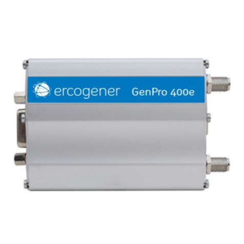
GSM modem
Instruction
s
Manual

GSM-TE809-EN_rev2.doc Page 2/8
Index
1- GSM COMMUNICATION .............................................................................................................................................3
1- 1 GSM Preliminary connection instructions .........................................................................................................................3
1- 1.1 Serial cable connection..................................................................................................................................................................... 3
1- 1.2 Antenna connection........................................................................................................................................................................... 3
1- 1.3 Power connection.............................................................................................................................................................................. 3
1- 1.4 SIM card settings............................................................................................................................................................................... 4
1- 1.5 LED diagnosis.................................................................................................................................................................................... 4
1- 1.6 On-board settings.............................................................................................................................................................................. 4
1- 2 SMS command and control .................................................................................................................................................5
1- 2.1 Phone numbers setting..................................................................................................................................................................... 5
1- 2.2 SMS commands................................................................................................................................................................................. 5

GSM-TE809-EN_rev2.doc Page 3/8
1- GSM COMMUNICATION
1- 1 GSM Preliminary connection instructions
The controller is equipped with a TE809 GSM system easy
to use.
1- 1.1 Serial cable connection
You can easily connect the GSM modem through the serial
cable 9 poles (code 51C3) male-female.
This cable consists of two connectors:
a) the male connector for the GSM modem
b) the female connector at TE809 side
Connect the cable as shown in the pictures 1 and 2: in figure
1 you can see the connection to the TE809.
In figure 2 you can see the connection with the GSM
modem.
1- 1.2 Antenna connection
Connect the antenna to the GSM modem as shown in the
figure. When the antenna connector is fixed to the antenna
and free from barriers you should have a good signal
quality. This antenna has a magnetic base that allows it to
be attached to metal supports without tools.
1- 1.3 Power connection
(8-32Vdc power supply)
Use the included power cord. These are the terminals of the
power cord:
c) free wires for power-on
d) connector on the GSM side
1
B
A
2
C
D

GSM-TE809-EN_rev2.doc Page 4/8
Connect the cables (figure below) to the power supply:
You have to connect the black and the brown together to the
battery negative, and the green and the blue together to the
battery positive.
Then, connect the other side of the connector to the GSM
modem:
1- 1.4 SIM card settings
When the system is connected, you must insert the SIM card
in the GSM modem. Before doing this, you should follow
these steps to make sure the SIM settings are correct:
- Insert the SIM card inside a mobile phone
- Turn on the phone and if asked the PIN code:
•Enter parameters in the "security" of the phone,
then disable the option to request a PIN.
•Turn off your phone then turn on again, should not
require a PIN. Otherwise, go back into security
menu and try again.
•VERY IMPORTANT! The PIN code request must be
disabled. Try sending an SMS message to another
phone, and reply with the receiver to the message
of the phone. If it doesn’t work, check in the
configuration of SMS if the phone "SMS Service
Number" is set correctly and then try again.
•When the system works, remove the SIM card from
the phone and put it into the GSM modem.
1- 1.5 LED diagnosis
When you power up the GSM modem, the LED flashes to
show that it is running. Also, after switching on:
- For a few seconds, it blinks slowly every 1 second: normal
condition of pre-operation
- After a few seconds after supply, it starts flashing every 2-
3 seconds: normal condition, operation enabled
- if it continues to blink slowly, something may be wrong.
Possible causes:
- SIM card not included
- PIN is not disabled
- GSM signal absent or very low, try to change the
place where the antenna is located
1- 1.6 On-board settings
It’s necessary to configure the serial port of the TE809 for the
GSM communication (see Connectivity setup of TE809):
If you use the RS232 port:
- Parameter D: Gsm modem
- Parameter E: 9600
If you use the RS485 port (if you have a RS232/RS485
converter, for example):
- Parameter B: Gsm modem
- Parameter C: 9600

GSM-TE809-EN_rev2.doc Page 5/8
1- 2 SMS command and control
1- 2.1 Phone numbers setting
Automatically when the GSM modem and the controller
TE809 are connected together, the TE809 sets the GSM
modem for all parameters. You only need to set the
parameters for automatic call (if different from the preset
from the factory) and mobile phone numbers.
WARNING:
Text messages must be wrote exactly following uppercase or
lowercase characters.
Follow exactly the syntax, paying attention not to insert any
“space” character in the message.
- Setting the numbers
To set up mobile phone numbers which the board must send
the messages to, it’s necessary to send to the TE809 a SMS
message that contains the number that you want to enable.
The syntax is the following (example for the first mobile
phone number):
SET1:+393451234567
As confirm about these settings, the TE809 answers the
phone with the following message:
SMS number +393451234567 set in position: 1
- Replace the numbers
If you wish, you can send (via your phone) other messages
to the GSM modem to set up additional numbers (up to 5),
for example:
SET2:394441112223
sets the second mobile phone number to which SMS will be
sent.
If you have already established a mobile number as Set 2,
and you want to change it, you can do so by sending
another
message with the new number, e.g:
SET2:+1199999999
the former is automatically deleted and replaced.
- Delete the numbers
If you want to permanently delete a phone number in the
heading of TE809, you can send a message with an "empty
number", for example:
SET3:
TE809 receives the message and sets the third mobile
number as empty.
1- 2.2 SMS commands
If you wish, you can also send commands to the TE809
which will then be automatically executed. This is the list of
commands:
Command Action
Man It selects the manual mode on the TE809
Aut It selects the automatic mode on the TE809
Test TE809 passes to test mode
Off It selects the Off mode on the TE809
Reset It permits to reset the alarms of the TE809
Start TE809 starts the generator in manual mode
Stop TE809 stops the generator in manual mode
Info TE809 responds with an SMS with all the
important informations and measures about the
system
Kr TE809 closes the mains contactor
Kg TE809 closes the generator contactor
Lock TE809 shows the alarm “system block” (set for
engine stop and doesn’t permit to start). To
make the alarm disappear, send again the
message “Lock”
The measures available in message "Info" are:
MODE: 0=Man, 1=Auto, 2=Reset/Off
VM: Mains voltages (only in TE809A and TE809Ats)
VG: Generator voltages
FG: Generator frequency
Vb: Battery voltage
H: Work hours
KG: Generator contactor status (0 = open, 1 = closed) (only
in TE809A and TE809Ats)
En: State of the motor (0 = Stop, 1 = started)
KR: Mains contactor status (1 = open, 0 = closed) (only in
TE809A and TE809Ats)
Fuel: Amount of fuel in the tank (in percentage) (only in
TE809A and TE809G)
kW: Active power
Info= sample message:
VGen:400; 403; 400; FG:50; Vbat:12,3; h:100; Eng:1;
Fuel%:100; KG:1; kW:23;
You can also send several commands in the same message
to the TE809 as:
Man;Start;Info
In this case, the TE809 will go into manual mode, starts the
generator will then sends a message like "Info" to read the
measurement.

GSM-TE809-EN_rev2.doc Page 6/8

GSM-TE809-EN_rev2.doc Page 7/8

GSM-TE809-EN_rev2.doc Page 8/8
Authorized distributor
Table of contents
