Radyne DMD50 User manual

DMD50
Universal Satellite Modem
Installation and Operation Manual
TM118
Revision 1.1
Radyne Corporation •3138 E. Elwood St. •Phoenix, AZ 85034 •(602) 437-9620 •Fax: (602) 437-4811 •www.radn.com


DMD50 Universal Satellite Modem Warranty Policy
TM118 – Rev. 1.1 iii
Warranty Policy WP
Radyne Corp. (Seller) warrants the items manufactured and sold by Radyne Corp. to be free of defects in
material and workmanship for a period of two (2) years from date of shipment Radyne Corp.’s obligation
under its warranty is limited in accordance with the periods of time and all other conditions stated in all
provisions of this warranty.
This warranty applies only to defects in material and workmanship in products manufactured by Radyne
Corp. Radyne Corp. makes no warranty whatsoever concerning products or accessories not of its
manufacture. Repair, or at the option of Radyne Corp., replacement of the Radyne Corp. products or
defective parts therein shall be the sole and exclusive remedy for all valid warranty claims.
Warranty Period
The applicable warranty period shall commence on the date of shipment from a Radyne Corp. facility to the
original purchaser and extend for the stated period following the date of shipment. Upon beginning of the
applicable Radyne Corp. warranty period, all customers’ remedies shall be governed by the terms stated or
referenced in this warranty. In-warranty repaired or replacement products or parts are warranted only for the
remaining unexpired portion of the original warranty period applicable to the repaired or replaced products or
parts. Repair or replacement of products or parts under warranty does not extend the original warranty
period.
Warranty Coverage Limitations
The following are expressly not covered under warranty:
1. Any loss, damage and/or malfunction relating in any way to shipping, storage, accident, abuse,
alteration, misuse, neglect, failure to use products under normal operating conditions, failure to use
products according to any operating instructions provided by Radyne Corp., lack of routine care
and maintenance as indicated in any operating maintenance instructions, or failure to use or take
any proper precautions under the circumstances.
2. Products, items, parts, accessories, subassemblies, or components which are expendable in
normal use or are of limited life, such as but not limited to, bulbs, fuses, lamps, glassware, etc.
Radyne Corp. reserves the right to revise the foregoing list of what is covered under this warranty.
Warranty Replacement and Adjustment
Radyne Corp. will not make warranty adjustments for failures of products or parts, which occur after the
specified maximum adjustment period. Unless otherwise agreed, failure shall be deemed to have occurred
no more than seven (7) working days before the first date on which Radyne Corp. receives a notice of
failure. Under no circumstances shall any warranty exceed the period stated above unless expressly agreed
to in writing by Radyne Corp.
Liability Limitations
This warranty is expressly in lieu of and excludes all other express and implied warranties, Including but not
limited to warranties of merchantability and of fitness for particular purpose, use, or applications, and all
other obligations or liabilities on the part of Radyne Corp., unless such other warranties, obligations, or
liabilities are expressly agreed to in writing by Radyne Corp.
All obligations of Radyne Corp. under this warranty shall cease in the event its products or parts thereof
have been subjected to accident, abuse, alteration, misuse or neglect, or which have not been operated and
maintained in accordance with proper operating instructions.

Warranty Policy DMD50 Universal Satellite Modem
iv TM118 – Rev. 1.1
In no event shall Radyne Corp. be liable for Incidental, consequential, special or resulting loss or damage of
any kind howsoever caused. Radyne Corp.’s liability for damages shall not exceed the payment, if any,
received by Radyne Corp. for the unit or product or service furnished or to be furnished, as the case may be,
which is the subject of claim or dispute.
Statements made by any person, including representatives of Radyne Corp., which are inconsistent or in
conflict with the terms of this warranty, shall not be binding upon Radyne Corp. unless reduced to writing
and approved by an officer of Radyne Corp.
Warranty Repair Return Procedure
Before a warranty repair can be accomplished, a Repair Authorization must be received. It is at this time
that Radyne Corp. will authorize the product or part to be returned to the Radyne Corp. facility or if field
repair will be accomplished. The Repair Authorization may be requested in writing or by calling:
Radyne Corp.
3138 E. Elwood St.
Phoenix, Arizona 85034 (USA)
ATTN: Customer Support
Phone: (602) 437-9620
Fax: (602) 437-4811
Any product returned to Radyne Corp. for examination must be sent prepaid via the means of transportation
indicated as acceptable to Radyne Corp. Return Authorization Number must be clearly marked on the
shipping label. Returned products or parts should be carefully packaged in the original container, if possible,
and unless otherwise indicated, shipped to the above address.
Non-Warranty Repair
When a product is returned for any reason, Customer and its shipping agency shall be responsible for all
damage resulting from improper packing and handling, and for loss in transit, not withstanding any defect or
nonconformity in the product. By returning a product, the owner grants Radyne Corp. permission to open
and disassemble the product as required for evaluation. In all cases, Radyne Corp. has sole responsibility
for determining the cause and nature of failure, and Radyne Corp.’s determination with regard thereto shall
be final.

DMD50 Universal Satellite Modem Preface
TM118 – Rev. 1.1 v
Preface P
This manual provides installation and operation information for the Radyne DMD50 Universal
Satellite Modem. This is a technical document intended for use by engineers, technicians, and
operators responsible for the operation and maintenance of the DMD50.
Conventions
Whenever the information within this manual instructs the operator to press a pushbutton switch
or keypad key on the Front Panel, the pushbutton or key label will be shown enclosed in "less
than" (<) and "greater than" (>) brackets. For example, the Reset Alarms Pushbutton will be
shown as <RESET ALARMS>, while a command that calls for the entry of a ‘7’ followed by
‘ENTER’ Key will be represented as <7,ENTER>.
Cautions and Warnings
A caution icon indicates a hazardous situation that if not avoided, may result in minor or moderate
injury. Caution may also be used to indicate other unsafe practices or risks of property damage.
A warning icon indicates a potentially hazardous situation that if not avoided, could result in death
or serious injury.
A note icon identifies information for the proper operation of your equipment, including helpful
hints, shortcuts, or important reminders.

Preface DMD50 Universal Satellite Modem
vi TM118 – Rev. 1.1
Trademarks
Product names mentioned in this manual may be trademarks or registered trademarks of their
respective companies and are hereby acknowledged.
Copyright
©2007, Radyne Corp. This manual is proprietary to Radyne Corp. and is intended for the
exclusive use of Radyne Corp.’s customers. No part of this document may in whole or in part, be
copied, reproduced, distributed, translated or reduced to any electronic or magnetic storage
medium without the express written consent of a duly authorized officer of Radyne Corp.
Disclaimer
This manual has been thoroughly reviewed for accuracy. All statements, technical information,
and recommendations contained herein and in any guides or related documents are believed
reliable, but the accuracy and completeness thereof are not guaranteed or warranted, and they
are not intended to be, nor should they be understood to be, representations or warranties
concerning the products described. Radyne Corp. assumes no responsibility for use of any
circuitry other than the circuitry employed in Radyne Corp. systems and equipment. Furthermore,
since Radyne Corp. is constantly improving its products, reserves the right to make changes in
the specifications of products, or in this manual at any time without notice and without obligation
to notify any person of such changes.
Record of Revisions
Revision
Level
Date Reason for Change
1.0 1-13-06 Initial Release
1.1 5-31-07 Update to reflect Web Browser Quick Setup Guide, Efficient Drop & Insert,
TCP/IP Internet, HSSI/G.703, HSSI/Ethernet, Updated Clock options,
Updated M&C descriptions, Added Near Side AUPC
Comments or Suggestions Concerning this Manual
Comments or suggestions regarding the content and design of this manual are appreciated. To
submit comments, please contact the Radyne Corp. Customer Service Department.

DMD50 Universal Satellite Modem Table of Contents
TM118 – Rev. 1.1 vii
Table of Contents ToC
Section 1 - Introduction ............................................................................................................. 1-1
1.0 Overview ______________________________________________________________ 1-1
1.1 Configurations __________________________________________________________ 1-1
1.1.1 Features/Options Installed at Time of Order__________________________________ 1-2
1.1.2 Feature Upgrades______________________________________________________ 1-2
1.1.3 Hardware Options______________________________________________________ 1-2
1.1.4 Radyne Installed Options________________________________________________ 1-2
1.2 Function Accessibility_____________________________________________________ 1-2
Section 2 - Installation ............................................................................................................... 2-1
2.0 Installation Requirements__________________________________________________ 2-1
2.1 Unpacking _____________________________________________________________ 2-2
2.2 Removal and Assembly ___________________________________________________ 2-2
2.3 Mounting Considerations __________________________________________________ 2-3
2.4 Initial Configuration Check _________________________________________________ 2-3
2.5 Modulator Checkout______________________________________________________ 2-5
2.5.1 Initial Power-Up________________________________________________________ 2-5
2.5.2 Factory Terminal Setup__________________________________________________ 2-5
2.6 Storage________________________________________________________________ 2-5
Section 3 - Theory of Operation................................................................................................ 3-1
3.0 Hardware ______________________________________________________________ 3-1
3.0.1 L-Band/IF Printed Circuit Card ____________________________________________ 3-1
3.0.2 Baseband Processing Printed Circuit Card___________________________________ 3-2
3.0.3 Enhanced Interface Printed Circuit Card_____________________________________ 3-3
3.1 Functional Block Diagram _________________________________________________ 3-3
3.1.1 Front Panel ___________________________________________________________ 3-4
3.1.2 Baseband Processing___________________________________________________ 3-4
3.1.3 Tx Baseband Processing ________________________________________________ 3-5
3.1.4 Rx Baseband Processing ________________________________________________ 3-5
3.2 Monitor & Control (M&C) Subsystem_________________________________________ 3-5
3.2.1 Terminal Port __________________________________________________________ 3-6

Table of Contents DMD50 Universal Satellite Modem
viii TM118 – Rev. 1.1
3.2.2 Modem Remote Communications (RLLP) ____________________________________ 3-6
3.2.3 Ethernet M&C Port _____________________________________________________ 3-6
3.2.4 Modem Monitor Status __________________________________________________ 3-6
3.3 Async Port / ES-ES Communications ________________________________________ 3-7
3.4 Internal Clock___________________________________________________________ 3-7
3.5 Loopback Features (Terrestrial & IF) _________________________________________ 3-8
3.6 Clocking Options________________________________________________________ 3-11
3.6.1TX Clock Options ______________________________________________________ 3-11
3.6.1.1 SCTE: Serial Clock Transmit External ____________________________________ 3-12
3.6.1.2 SCT: Serial Clock Transmit ____________________________________________ 3-12
3.6.2 RX Buffer Clock Options _______________________________________________ 3-12
3.6.2.1 RX SAT Clock_______________________________________________________ 3-13
3.6.2.2 SCTE: Serial Clock Transmit External ____________________________________ 3-13
3.6.2.3 SCT: Serial Clock Transmit_____________________________________________ 3-13
3.6.2.4 EXT CLK/EXT BNC: External Clock, J16__________________________________ 3-13
3.6.2.5 EXT IDI: Insert Data In________________________________________________ 3-13
3.6.3 EXT REF: External Reference, Top BNC Port, J10 ___________________________ 3-14
3.7 RS530/422/V.35 Interfafce (Standard)_______________________________________ 3-14
3.7.1 G.703 Interface (Optional)_______________________________________________ 3-14
3.7.2 HSSI Interface (Optional) _______________________________________________ 3-14
3.7.3 Ethernet Data Interface (Optional) ________________________________________ 3-14
3.8 Reed-Solomon Codec ___________________________________________________ 3-15
3.8.1 Reed-Solomon Operation in the DMD50____________________________________ 3-15
3.8.2 Reed-Solomon Code Rate ______________________________________________ 3-15
3.8.3 Interleaving __________________________________________________________ 3-15
3.9 Asynchronous Overhead Operation (Framing/Multiplexer Capability) _______________ 3-17
3.10 Standard IBS Mode ____________________________________________________ 3-19
3.11 Asynchronous Multiplexer Mode__________________________________________ 3-19
3.12 ESC Backward Alarms__________________________________________________ 3-20
3.12.1 To Disable the ESC Backward Alarms ____________________________________ 3-21
3.13 Satellite Control Channel (SCC)___________________________________________ 3-21
3.13.1 SCC Framing Structure________________________________________________ 3-21
3.13.2 Aggregate Data Rate _________________________________________________ 3-22
3.13.3 Overhead Rate Comparison ____________________________________________ 3-22
3.13.4 Actual Overhead Rate Calculation _______________________________________ 3-23
3.13.5 SCC Overhead Channel Setup__________________________________________ 3-24
3.14 EDMAC Satellite Framing/Deframing Mode__________________________________ 3-25

DMD50 Universal Satellite Modem Table of Contents
TM118 – Rev. 1.1 ix
3.15 Locating the ID Code Operational Procedure ________________________________ 3-25
3.16 Strap Codes__________________________________________________________ 3-25
Section 4 - User Interfaces ........................................................................................................ 4-1
4.0 User Interfaces__________________________________________________________ 4-1
4.1 Front Panel User Interface_________________________________________________ 4-1
4.1.1 LCD Front Panel Display_________________________________________________ 4-2
4.1.2 Cursor Control Arrow Keys _______________________________________________ 4-2
4.1.3 Numeric Keypad _______________________________________________________ 4-2
4.1.4 Front Panel LED Indicators_______________________________________________ 4-3
4.2 Parameter Setup ________________________________________________________ 4-3
4.3 Front Panel Control Screen Menus __________________________________________ 4-4
4.3.1 Main Menus___________________________________________________________ 4-4
4.3.2 Modulator Menu Options and Parameters ___________________________________ 4-5
4.3.3 Demodulator Menu Options and Parameters ________________________________ 4-11
4.3.4 Interface Menu Options and Parameters ___________________________________ 4-16
4.3.6 Monitor Menu Options and Parameters ____________________________________ 4-21
4.3.7 Alarms Menu Options and Parameters_____________________________________ 4-23
4.3.8 System Menu Options and Parameters ____________________________________ 4-31
4.3.9 Test Menu Options and Parameters _______________________________________ 4-39
4.4 Terminal Mode Control___________________________________________________ 4-41
4.4.1 Modem Terminal Mode Control___________________________________________ 4-41
4.4.2 Modem Setup for Terminal Mode _________________________________________ 4-41
4.5 Terminal Port User Interface ______________________________________________ 4-41
4.6 Connecting the Terminal _________________________________________________ 4-42
4.7 Terminal Screens_______________________________________________________ 4-42
4.8 RS485 Remote Port Interface (RLLP Protocol) ________________________________ 4-42
4.8.1 Protocol Structure _____________________________________________________ 4-43
4.9 Ethernet Remote Port Interface (SNMP & Web Browser) ________________________ 4-43
Section 5 - Rear Panel Interfaces.............................................................................................. 5-1
5.0 Connections____________________________________________________________ 5-1
5.1 Compact Flash__________________________________________________________ 5-2
5.2 Power Input Modules _____________________________________________________ 5-2
5.2.1 AC Power Input Module _________________________________________________ 5-2
5.2.2 DC Power Input/Switch __________________________________________________ 5-2
5.3 Chassis Connections (Standard)_____________________________________________ 5-2
5.3.1 EXT REF (J10) ________________________________________________________ 5-2

Table of Contents DMD50 Universal Satellite Modem
x TM118 – Rev. 1.1
5.3.2 TX IF (J11) ___________________________________________________________ 5-2
5.3.3 TX L-Band IF (J12) _____________________________________________________ 5-2
5.3.4 RX IF (J13) ___________________________________________________________ 5-2
5.3.5 RX L-Band IF (J14) _____________________________________________________ 5-3
5.3.6 ALARM (J15)__________________________________________________________ 5-3
5.3.7 EXT CLK (J16) ________________________________________________________ 5-3
5.3.8 ASYNC (J17)__________________________________________________________ 5-4
5.3.9 J18 _________________________________________________________________ 5-4
5.3.10 EIA-530 (J19) ________________________________________________________ 5-4
5.3.11 REMOTE (J20) _______________________________________________________ 5-5
5.3.12 ETHERNET (J21) _____________________________________________________ 5-6
5.4 G.703 IDR/IBS Interface (Optional) __________________________________________ 5-6
5.4.1 ESC ALARM (J1) ______________________________________________________ 5-6
5.4.2 64K AUDIO (J2) _______________________________________________________ 5-7
5.4.3 8K DATA (J3) _________________________________________________________ 5-8
5.4.4 G.703 BAL (J4) ________________________________________________________ 5-8
5.4.5 SWITCH INTERFACE (J5) _______________________________________________ 5-9
5.4.6 SD (DDI) (J6) ________________________________________________________ 5-12
5.4.7 DDO (J7)____________________________________________________________ 5-12
5.4.8 IDI (J8) _____________________________________________________________ 5-12
5.4.9 SD (IDO) (J9) ________________________________________________________ 5-12
5.5 Ethernet Data Interface (Optional) __________________________________________ 5-12
5.6 High-Speed Serial Interface (HSSI) (Optional)_________________________________ 5-13
5.6.1 HSSI (J6)____________________________________________________________ 5-13
5.7 ASI/DVB/M2P Interface (Optional)__________________________________________ 5-14
5.7.1 ASI IN (J1)___________________________________________________________ 5-14
5.7.2 ASI OUT (J2)_________________________________________________________ 5-14
5.7.3 DVB/M2P IN (J3)______________________________________________________ 5-14
5.7.4 DVB/M2P OUT (J4)____________________________________________________ 5-16
5.8 Ethernet Data Interface (Optional) __________________________________________ 5-18
5.9 HSSI / G.703___________________________________________________________ 5-18
5.9.1 64K AUDIO (J2) ______________________________________________________ 5-19
5.9.2 8K DATA (J3) ________________________________________________________ 5-20
5.9.3 G.703 BAL (J4) _______________________________________________________ 5-21
5.9.4 ESC ALARM (J5) _____________________________________________________ 5-22
5.9.5 SD (DDI) (J6) ________________________________________________________ 5-22
5.9.6 DDO (J7)____________________________________________________________ 5-22

DMD50 Universal Satellite Modem Table of Contents
TM118 – Rev. 1.1 xi
5.9.7 IDI (J8) _____________________________________________________________ 5-23
5.9.8 SD (IDO) (J9) ________________________________________________________ 5-23
5.10 HSSI / Ethernet (J1) ____________________________________________________ 5-23
5.11 Ethernet Data Interface _________________________________________________ 5-24
5.12 GigE Interface_________________________________________________________ 5-24
Section 6 - Maintenance and Troubleshooting........................................................................ 6-1
6.0 Periodic Maintenance_____________________________________________________ 6-1
6.0.1 Clock Adjustment ______________________________________________________ 6-1
6.1 Troubleshooting _________________________________________________________ 6-1
6.1.1 Alarm Faults __________________________________________________________ 6-2
6.1.1.1 Major Tx Alarms______________________________________________________ 6-2
6.1.1.2 Major Rx Alarms______________________________________________________ 6-3
6.1.1.3 Minor Tx Alarms______________________________________________________ 6-3
6.1.1.4 Minor Rx Alarms______________________________________________________ 6-4
6.1.1.5 Drop and Insert Alarms ________________________________________________ 6-5
6.1.1.6 Common Major Alarms ________________________________________________ 6-5
6.1.2 Alarm Masks __________________________________________________________ 6-6
6.1.2.1 Active Alarms ________________________________________________________ 6-6
6.1.2.1.1 Major Alarms_______________________________________________________ 6-6
6.1.2.1.2 Minor Alarms_______________________________________________________ 6-6
6.1.2.1.3 Common Equipment Faults____________________________________________ 6-6
6.1.2.2 Latched Alarms ______________________________________________________ 6-6
6.1.2.3 Backward Alarms _____________________________________________________ 6-7
6.2 IBS Fault Conditions and Actions____________________________________________ 6-7
Section 7 - Technical Specifications ........................................................................................ 7-1
7.0 Data Rates_____________________________________________________________ 7-1
7.1 Modulator______________________________________________________________ 7-1
7.2 Demodulator____________________________________________________________ 7-2
7.3 Plesiochronous Buffer ____________________________________________________ 7-2
7.4 Monitor and Control ______________________________________________________ 7-2
7.5 DMD50 Drop and Insert (Optional)___________________________________________ 7-3
7.6 Terrestrial Interfaces _____________________________________________________ 7-3
7.7 IDR/ESC Interface (Optional)_______________________________________________ 7-3
7.8 IBS/Synchronous Interface (Standard)________________________________________ 7-3
7.9 High-Speed Serial Interface (HSSI) __________________________________________ 7-3
7.10 ASI __________________________________________________________________ 7-3

Table of Contents DMD50 Universal Satellite Modem
xii TM118 – Rev. 1.1
7.11 DVB/M2P _____________________________________________________________ 7-3
7.12 Ethernet Data Interface (Optional) __________________________________________ 7-3
7.13 HSSI / G.703___________________________________________________________ 7-4
7.14 HSSI /ETHERNET ______________________________________________________ 7-4
7.15 IDR/ESC T3/E3/STS11 Interface (Optional) __________________________________ 7-4
7.16 Environmental _________________________________________________________ 7-4
7.17 Physical ______________________________________________________________ 7-4
7.18 DMD50 Data Rate Limits _________________________________________________ 7-5
7.18.1 Non-DVB____________________________________________________________ 7-5
7.18.2 DVB________________________________________________________________ 7-6
7.19 BER Specifications _____________________________________________________ 7-8
7.19.1 BER Performance (Viterbi) ______________________________________________ 7-8
7.19.2 BER Performance (Sequential)___________________________________________ 7-9
7.19.3 BER Performance (Viterbi with Reed-Solomon) _____________________________ 7-10
7.19.4 BER Performance (Turbo)______________________________________________ 7-11
7.19.5 BER Performance (8PSK Trellis) ________________________________________ 7-13
7.19.6 BER Performance (8PSK Turbo) ________________________________________ 7-15
7.19.7 BER Performance (16QAM Viterbi)_______________________________________ 7-16
7.19.8 BER Performance (16QAM Viterbi with Reed-Solomon) ______________________ 7-17
7.19.9 BER Performance (16QAM Turbo) _______________________________________ 7-18
7.19.10 BER Performance ((O)QPSK Turbo) ____________________________________ 7-19
7.19.11 BER Performance (8PSK Turbo) _______________________________________ 7-19
7.19.12 BER Performance (16QAM Turbo) ______________________________________ 7-19
7.19.13 AGC Output Voltage _________________________________________________ 7-24
Appendix A - Product Options ..................................................................................................A-1
A.0 Hardware Options _______________________________________________________ A-1
A.0.1 G.703/IDR ESC Interface ________________________________________________ A-1
A.0.2 Internal High Stability ___________________________________________________ A-1
A.0.3 DC Input Prime Power __________________________________________________ A-1
A.0.4 ASI/RS-422 Parallel ____________________________________________________ A-1
A.0.5 ASI/LVDS Parallel______________________________________________________ A-1
A.0.6 HSSI ________________________________________________________________ A-1
A.0.7 Ethernet Data Interface__________________________________________________ A-1
A.0.8 HSSI / G.703 _________________________________________________________ A-1
A.0.9 HSSI / ETHERNET ____________________________________________________ A-2
A.0.10 Turbo Product Codec / Variable Reed-Solomon Codec card____________________ A-2
A.1 Customized Options _____________________________________________________ A-2

DMD50 Universal Satellite Modem Table of Contents
TM118 – Rev. 1.1 xiii
Appendix B - Front Panel Upgrade Procedure ........................................................................B-1
B.0 Introduction ____________________________________________________________ B-1
B.1 Required Equipment _____________________________________________________ B-1
B.2 Upgrade Procedure ______________________________________________________ B-1
B.3 Demonstration Procedure _________________________________________________ B-3
B.3.1 Running in Demonstration Mode __________________________________________ B-5
B.3.2 Canceling Demonstration Mode ___________________________________________ B-6
Appendix C - Carrier Control.....................................................................................................C-1
C.0 States ________________________________________________________________ C-1
C.1 Carrier Off _____________________________________________________________ C-1
C.2 Carrier On _____________________________________________________________ C-1
C.3 Carrier Auto____________________________________________________________ C-1
C.4 Carrier VSat____________________________________________________________ C-1
C.5 Carrier RTS ____________________________________________________________ C-2
Appendix D - Strap Codes .........................................................................................................D-1
D.1 Strap Codes____________________________________________________________ D-1
D.2 Sample Applications _____________________________________________________ D-4
D.2.1 Operational Case Examples______________________________________________ D-5
Appendix E - TCP/IP Ethernet Setup ........................................................................................E-1
E.0 Introduction_____________________________________________________________ E-1
E.1 TCP/IP Network Configuration ______________________________________________ E-1
E.2 Network Configuration Summary ____________________________________________ E-3
E.3 Ethernet Test ___________________________________________________________ E-3
E.3.1 Connecting the Modem Ethernet Cable to a Network Link ______________________ E-3
E.3..2 Connecting the Modem Ethernet Cable Directly to a Computer (without a Network) __ E-3
E.3.3 Testing the Ethernet connection using the Ping Program (Optional)_______________ E-6
Appendix F - Web Browser Setup Guide ................................................................................. F-1
F.0 Introduction ____________________________________________________________ F-1
F.1 WEB Users Configuration _________________________________________________ F-1
F.1.1 Change Web User Name ________________________________________________ F-3
F.1.2 Change Authentication Password__________________________________________ F-3
F.1.3 Change Access Rights __________________________________________________ F-3
F.2 Modem Web Site ________________________________________________________ F-4
F.3 Web Page Appearance ___________________________________________________ F-5

Table of Contents DMD50 Universal Satellite Modem
xiv TM118 – Rev. 1.1
Appendix G - AUPC Operation ................................................................................................. G-1
G.1 Automatic Uplink Power Control (AUPC Operation) _____________________________ G-1
G.1.1 Radyne AUPC_________________________________________________________ G-1
G.1.2 EF AUPC____________________________________________________________ G-2
G.1.3 Near Side AUPC _______________________________________________________ G-2
Appendix H - Drop and Insert (D&I)____________________________________________ H-1
H.0 Drop and Insert (D&I) ____________________________________________________ H-1
H.0.1 Drop Only ____________________________________________________________ H-3
H.0.2 Insert Only ___________________________________________________________ H-3
H.0.3 Mode Selection________________________________________________________ H-5
H.0.3.1 PCM-30 ____________________________________________________________ H-5
H.0.3.2 PCM-30C___________________________________________________________ H-5
H.0.3.3 PCM-31 ____________________________________________________________ H-5
H.0.3.4 PCM-31C___________________________________________________________ H-5
H.0.3.5 T1-D4/T1-D4-S ______________________________________________________ H-6
H.0.3.6 T1-ESF/T1-ESF-S ____________________________________________________ H-6
H.0.4 Multi Destinational Systems ______________________________________________ H-6
H.0.5 Drop and Insert Mapping ________________________________________________ H-7
H.1 Configuring the Modem for Drop and Insert ___________________________________ H-9
H.1.1 Data Rate ____________________________________________________________ H-9
H.1.2 Operational Network Specification ________________________________________ H-10
H.1.3 Terrestrial Framing - Drop Mode/Insert Mode _______________________________ H-10
H.1.3.1 Insert Terrestrial Frame Source_________________________________________ H-11
H.1.4 D&I Sample Configurations and D&I Clock Setup Options______________________ H-11
H.2 D&I Maps and Map Editing _______________________________________________ H-15
Appendix I - Efficient Drop & Insert........................................................................................... I-1
I.0 Introduction______________________________________________________________ I-1
I.1 Prerequisite______________________________________________________________ I-1
I.2 Efficient Drop & Insert Mode_________________________________________________ I-2
I.2.1 Calculating the Required Satellite Bandwidth___________________________________ I-3
I.2.2 Calculating the Basic Efficient D&I Rate_______________________________________ I-3
I.2.3 Calculating the Efficient D&I Rate with E1 Signaling______________________________ I-3
I.2.4 Calculating the Efficient D&I Rate with Enhanced Asynchronous Overhead ___________ I-3
Glossary ...................................................................................................................................... J-1

DMD50 Universal Satellite Modem Table of Contents
TM118 – Rev. 1.1 xv


DMD50 Universal Satellite Modem Introduction
TM118 – Rev. 1.1 1-1
Introduction 1
This chapter provides an overview of the DMD50 Universal Satellite Modem. When describing
the equipment, it may be referred to as “the modem”, or “the unit”.
1.0 Overview
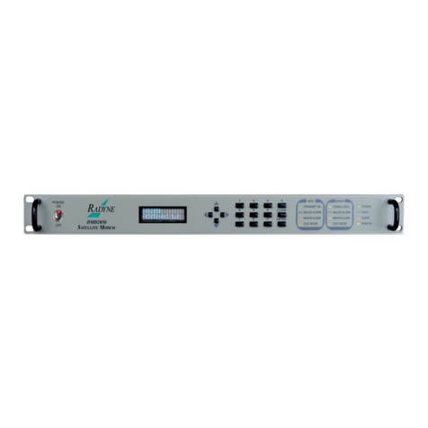
The Radyne Universal Satellite Modem (Figure 1-1) offers the best features of a sophisticated
programmable IBS/IDR and Closed Network Modem, at an affordable price.
Figure 1-1. Universal Satellite Modem Front Panel
This versatile equipment package combines unsurpassed performance with numerous user-
friendly Front Panel Programmable Functions. The unit provides selectable functions for different
services: Intelsat IDR and IBS, as well as closed networks. All of the configuration and Monitor
and Control (M&C) Functions are available at the Front Panel. Operating parameters, such as
variable data rates, FEC Code Rate, modulation type, IF Frequencies, IBS/IDR Framing and
interface type can be readily set and changed at the Front Panel by earth station operations
personnel.
The modem operates at all standard IBS and IDR Data Rates up to 8.448 Mbps. Selection of any
data rate is provided over the range of 2.4 Kbps to 52 Mbps in 1 bps steps.
For applications requiring system redundancy, the Modem may be used with the Radyne RCS11
1:1 Redundancy Switch or the RCS20 M:N (N < 9) Redundancy Switch. An Internal Engineering
Service Channel Unit is available to provide voice, data, and alarms for Intelsat IDR applications.
A full range of Industry Standard Interfaces are available. Interface types are selectable from
V.35, RS-232, RS-422/-530, ITU G.703, HSSI, ASI, DVB/M2P and Ethernet Bridge.
1.1 Configurations
The unit can be configured in the following ways:
features and options that are installed when the unit is ordered
feature upgrades
hardware options that are installed to a unit that is sent to a Radyne facility
hardware options that the user can install at their own location

Introduction DMD50 Universal Satellite Modem
1-2 TM118 – Rev. 1.1
1.1.1 Features/Options Installed at Time of Order
Features installed at the time of ordering are the options pre-installed/initialized in the factory prior
to shipment. These can be reviewed from the front panel. Refer to Section 4, User Interfaces for
information on how to view these features.
Factory installed options are chassis and board configurations that are introduced during
manufacture.
1.1.2 Feature Upgrades
Feature Upgrades are a simple and quick way of changing the feature set of an installed modem.
Feature upgrades are how most options are implemented. Features may be purchased at any
time by contacting a Radyne Corp. salesperson. Refer to Section 4 and Appendix D, for
information on how upgrade features are enabled.
1.1.3 Hardware Options
Hardware options (refer to Appendix A) are purchased parts that can be installed into the unit at
the customer’s site. A screwdriver is normally the only tool required. Please contact the Radyne
Corp. Customer Service Department for information not limited to availability and to shipping
costs.
Only authorized service personnel should handle and install optional
hardware options.
1.1.4 Radyne Installed Options
Units may also be sent to the Radyne Corp. facility for hardware option installation. Please
contact the Radyne Corp. Customer Service Department for information not limited to availability
and to shipping costs.
1.2 Function Accessibility
All functions can be accessed with a terminal or personal computer via a serial link for complete
remote monitoring and control capability.

DMD50 Universal Satellite Modem Introduction
TM118 – Rev. 1.1 1-3
Other manuals for DMD50
1
This manual suits for next models
1
Table of contents
Other Radyne Modem manuals

Radyne
Radyne OM20 User manual

Radyne
Radyne DMD20 LBST User manual

Radyne
Radyne DMD2401 LB User manual

Radyne
Radyne DMD2050 Manual

Radyne
Radyne DMD2050 User manual

Radyne
Radyne DMD15 User manual

Radyne
Radyne DMD20 LBST User manual

Radyne
Radyne OM20 User manual

Radyne
Radyne DMD50 User manual

Radyne
Radyne DMD2401 IBS User manual
Popular Modem manuals by other brands

Aztech
Aztech UM9800-A user manual

ZyXEL Communications
ZyXEL Communications Prestige 841 quick start guide

CTI Products
CTI Products SLM SiteLync user guide

Eicon Technology
Eicon Technology Diva T/A reference guide

Draytek
Draytek Vigor 160 Series quick start guide

MaxStream
MaxStream 9XCite-PKG-R product manual