TecnoVideo PTZ250D-CRLED User manual

PTZ250D-CRLED
Stainless Steel PTZ Camera Station
with
integrated IR LED illuminator
Installation manual
Issue 20200115

TA LE OF CONTENTS
Page
INSTALLING THE UNIT 03
CERTIFICATIONS 03
IR LED ILLUMINATOR ELECTRICAL CONNECTIONS 04
IR LED calibration and s ttings 04
SETTING THE UNIT ADDRESS 05
PERFORM PTZ ELECTRICAL CONNECTIONS 05
Auxiliary functions (availabl on CR v rsions only) 06
Password and r s t button (availabl on CR v rsions only) 06
D fault limits 07
Changing th d fault limits 07
Pr s t 07
Sp cial auxiliary functions (availabl on CR v rsions only) 07
INSTALLING THE NOZZLE BRACKET 07
DIMENSIONS 08
2

INSTALLING THE UNIT
i
Prior to installation and op ration, r ad car fully all instructions in this manual and h d all warnings.
Unpack this quipm nt and handl it car fully. If th packag app ars to b damag d, notify th shipp r imm diat ly.
Us th original packaging to transport th unit. Disconn ct pow r supply b for moving it. In cas of r turning th quipm n
t,
th original packaging must b us d.
Mak sur that th installation surfac can support at l ast four
tim s th w ight of th unit in normal op rating conditions. In cas
of xc ssiv xt rnal str ss ( .g. vibration, strong winds or impact), th quipm nt may n d additional m ans of prot ction.
Prop r stainl ss st l hardwar should b car fully chos n to fast n th unit to th surfac s.
Us caution wh n lifting and ass mbling th unit. It is r comm nd d that non-
slip prot ctiv glov s b worn during installation.
Th unit could b ar sharp dg s.
Trying to manually forc th motors will r sult in damaging th d vic and will void th warranty.
WARNING: Hazardous moving parts: th d vic is r mot ly controll d and may chang position at any tim . Wh n installing,
choos a plac wh r moving parts could not hit anyon or any obj ct, cr ating hazardous situations.
To maintain th IP rating of th unit, ad quat cabl glands must b us d. Th unit must b tightly clos d wh n op rating and
th
cabl glands must b tight n up till an 8 Nm torqu ratio. Ch ck th prop r position of th s al in its groov on th flang s.
For s curity r asons, do not install th unit in th proximity of wat r contain rs and n v r push obj cts or pour liquids int
o th unit.
Th unit can b saf ly us d in damp nvironm nts or outdoors, as long as th conn ctors ar prop rly s al d.
Compl t th installation p rforming th l ctrical and vid o conn ctions according to th instructions in th cam ra install
ation
manual.
Vid o and data cabl s should not shar th sam conduit with supply voltag cabl s. Wh n v r EMC is
an issu , ad quat ly
shi ld d cabl s must b us d.
Op n only th cov rs point d out in this installation manual. Oth r cov rs should b op n only by th manufactur r.
Tight ning/loosing th scr ws using automatic tools such as drill driv rs may r sult in damag d thr ads.
This quipm nt has b n d sign d to fit in harsh nvironm nts r quiring littl or no maint nanc . Sugg st d insp ction int rv
al
is 6 months, but xtr m ly harsh nvironm nts may r quir mor fr qu nt insp ction and maint nanc ch cks. O
n ach insp ction
ch ck th O-ring s als and th v ntual window wip r blad int grity. R plac th m if n c ssary.
Ch ck cabl s, l ctrical conn ctions and mounting hardwar for int grity and tightn ss. R plac or tight n any damag d/loos
part.
Aft r th installation of th unit, th d siccant bag must b plac d insid th Pan & Tilt unit, assuring it won't b damag d
by
rotating and moving parts.
Pr s t Recall 99 calibrat s th Cam ra Pots in cas of motoriz d l ns (n d d th first tim th cam ra is conn ct d).
Op rating t mp ratur : -20° +60° C (-4° +140° F).
H ating l m nt may still b hot for som tim , v n aft r b ing shut off.
h
B for
p rforming any op ration, turn off th pow r. Th installation of th unit can b p rform d only by qualifi d p rsonn l in
accordanc with th r gulations in forc . Do not conn ct th unit to a supply circuit unl ss th installation is compl t d.
Ch ck car fully th supply voltag mark d on th lab l. Incorr ct Pow r Supply Voltag may damag th unit. Do not ov rload t
h
t rminal conn ction, as it may caus a fir or l ctrical shock hazard. Supply voltag tol ranc = ±10%.
An all-pol mains
switch with an op ning distanc b tw n th contacts at l ast 3 mm in ach pol must b incorporat d in th
l ctrical installation. Th switch must b quipp d with prot ction against th fault curr nt towards th ground (diff r nti
al) and
th ov rcurr nt
(magn toth rmal, maximum 15A). It must b v ry quickly r cognizabl and r adily acc ssibl . A suitabl blow fus
must also b install d for prot ction.
For conn ction to th mains, us a multipolar cabl having minimum 3x1,5 mm
2
(15 AWG). Th main cabl
must b at l ast
prot ct d by an ordinary PVC sh ath.
Fast n all th cabl s insid th housing with cabl s ti s or oth r fixing m ans to avoid th l ctrical contact with surround
ing parts
in cas that t rminal blocks scr w off.
El ctrical
conn ctions (such as plugs and cords) must b prot ct d from pot ntial hazardous nvironm ntal factors ( .g. foot traffic,
hitting obj cts).
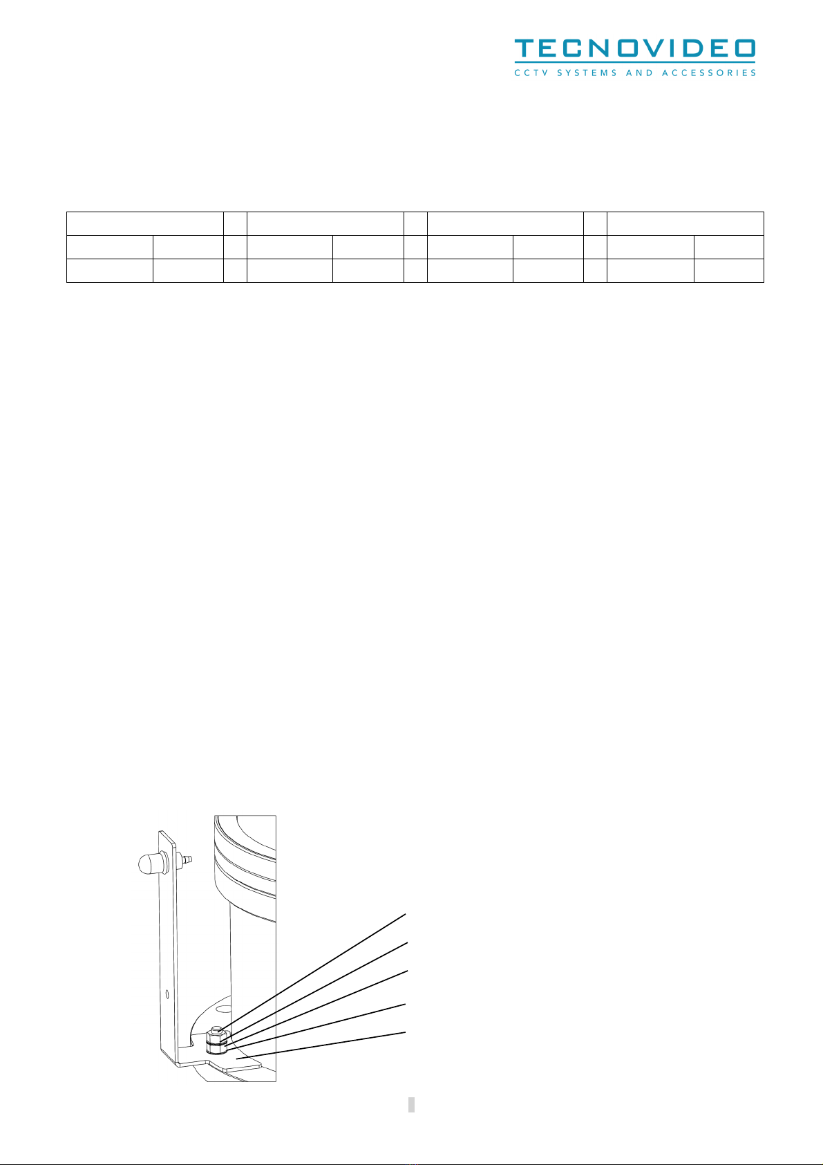
Ensur that th unit cas is prop rly arth d, conn cting all th arth ground studs. Earth cabl should b about
10mm long r than
th oth r cabl s on th conn ctor, in such way that it won't b accid ntally disconn ct d if th cabl is str tch d or pull d.
Wh n l aving th unit unus d for long p riods, disconn ct supply cabl s.
CERTIFICATIONS
Ingr ss Prot ction (EN 60529) IP66/IP67
EMC EN 61000-6-3:2007; EN 50130-4:1995 + A1:1998 + A2:2003
LVD EN 60950-1:2006 + A11:2009
RoHS 2011/65/EU
WEEE 2012/19/EU
3

IR LED ILLUMINATOR ELECTRICAL CONNECTIONS
Connector
Pin
Connector
Pin
M1
1 GND
M4
1 Not conn ct d
2 24V~/V
⎓
(V2/-) 2 Not conn ct d
3 24V~/V
⎓
(V1/+)
M5
1 +12V
⎓
AUX
M2
1 IR LEDs (V+) 2 0V
⎓
AUX
2 IR LEDs (V-)
M6
1 IN cmd START C+ or Dry contact
3 Light s nsor photoc ll C +
2 IN cmd START E- or Dry contact
4 Light s nsor photoc ll E -
M3
1 OUT Day&Night_COM photor lay
2 OUT Day&Night_NO photor lay
3 IN cmd STROBO C+
4 IN cmd STROBO E-
Connector Name Notes
M1
AC/DC Pow r supply Input
/
M2
IR LEDs pow r & Light s nsor photoc ll
Supply voltag to th IR LEDs &
xt rnal
l
ight s nsor
photoc ll
signal
M3
Day&Night
photor lay
Output signal for day/night mod (night=ON, day=OFF).
M4
Factory R s rv d
Not conn ct d
M5
DC output
For
auxiliary quipm nt: do not xc d 0.1A
M6
Inputs
Dry contact/Op n coll ctor (NPN) input for IR LEDs activation
(Exampl : xt rnal cam ra output)
IR LED calibration and settings
Th IR01 board install d insid th IR LED illuminator is quipp d with four LEDs. Th DL1 LED (gr n) is on wh n th board is corr ctly
pow r d. Th DL2 LED (y llow) is on wh n th IR LEDs ar int rrupt d (op n-l d). Th DL3 LED (r d) is on wh n th IR LEDs ar not
activat d or wh n th IR LEDs ar in short-circuit if activat d. Th DL4 LED (y llow) is on wh n th IR LEDs ar in th activation phas
during its hyst r sis d lay-tim .
S1 button is us d for manual IR LEDs activation t st.
TR3 trimm r is us d for adjusting th s nsitivity of th light s nsor photoc ll.
Count r clockwis rotation d cr as s s nsitivity. Clockwis rotation incr as s it.
S tting it to 0 disabl th activation from light s nsor photoc ll.
J6 jump r is us d for instant or d lay d IR LEDs Activation.
Conn ction b tw n 1 and 2 trigg rs on hyst r sis d lay d activation and d activation (in this cas , DL4 shows th d lay d phas ).
Conn ction b tw n 2 and 3 trigg rs on instant activation and d activation (in this cas , DL4 is always OFF).
4

SETTING THE UNIT ADDRESS
Th d vic can b controll d from a PC with RS 485 conv rt r using a suitabl program (for xampl : Visual Studio).
To pr v nt damag s and to assur a pr cis pr s t position, th r c iv r slows th motion as it g ts n ar to th pr s t position.
Th r c iv r is quipp d with four LEDs. Th L1 LED (gr n) is on wh n th r c iv r is corr ctly pow r d. Th L2 LED (gr n) puls s
wh n th r c iv r r c iv s data. Th L3 LED (y llow) puls s wh n th r c iv r s nds data. Th L4 LED (r d) puls s wh n th r c iv r
is ov rh at d.
Th 8 way dip-switch on th t l m try r c iv r (DIS1) can b us d to s t up th unit addr ss (binary).
Wh n a switch is on th ON position, th r lativ digit has valu 1, oth rwis th valu is 0. Switch 1
is r f rr d to th l ast significant digit (2
0
), whil switch 8 is r f rr d to th most significant digit (2
7
).
For xampl , th addr ss 13 (00001101 in binary) can b s t up turning ON th switch 1, 3 and 4 (s
figur ).
PERFORM PTZ ELECTRICAL CONNECTIONS
Op n th bas junction box and p rform th conn ctions on th MF_RTX int rfac board. Conn ctions through th plug-in blocks ar
mad by T cnovid o, whil scr w t rminal blocks ar us d for th fi ld installation. It must b not d that ach plug-in conn ctor is
diff r nt in shap and/or colour to avoid any wrong conn ction. Th conn ctions should b p rform d according to th b low:
Field installation
ID Name Notes
M1 Supply voltag D p nding on mod l: 24V
~
or 230V
~
50/60Hz. Maximum curr nt r quir d: 5A.
M4 Data input (RS485) Standard: P lco D Protocol to control T cnovid o t l m try r c iv rs.
M6 Auxiliary DC
output
12V
⎓
. Max: 0,4A. Any conn ction of this Aux must b p rform d insid th bas junction box.
M7 Auxiliary AC output D sign d to activat wash r syst ms. G n rally activat d via AUX 2 in P lco D. Th activation lasts
5 s conds.
M9 Auxiliary data input If n d d, contact T cnovid o for furth r information.
CN2 Eth rn t Signal out and/or POE supply voltag . Us shi ld d or unshi ld d cabl according to th n ds.
CH1_OUT Analogic output Us a high quality coaxial cabl with a shi ld d BNC conn ctor.
Tecnovideo connectors
ID Name Notes
M3 Supply voltag Supply voltag for t l m try r c iv r and any 24V
~
d vic insid th unit.
M5 RS485 bus Communication bus (RS485) for t l m try r c iv r. This provid s th auxiliary DC output (M7).
M8 Auxiliary AC output Auxiliary AC output conn ct d to AUX 2 of t l m try r c iv r.
CN1 Eth rn t Signal and/or POE supply voltag .
CH1_IN Analogic output Analogic vid o conn ct d to th cam ra.
CN3 Auxiliary conn ctor Us d for custom configurations.
CN4 Sam as abov Duplication of CN3.
5
1 2 3 4 5 6 7 8
ON (1)

Fuse values
Th following fus valu s ar us d, d p nding on th supply voltag :
24 VAC supply voltage
Fuse name
Fuse value
F1 10A T 250V~ 5x20
F2 10A T 250V~ 5x20
230 VAC supply voltage
Fuse name Fuse value
F1 6,3A T 250V~ 5x20
F2 10A T 250V~ 5x20
All th fus must b T typ (tim lag).
Diff r nt supply voltag can b suppli d and may r quir diff r nt fus valu s. In such cas s, pl as contact T cnovid o.
Auxiliary functions (available on CR versions only)
Th unit has 8 auxiliary functions, as d scrib d b low:
-
Aux1 is us d for Wip r activation only (this function will activat th wip r for approx. 10 s conds).
-
Aux2 is us d for Wash r pump activation only (this function will activat th wash r pump for approx. 5 s conds).
-
Aux3 is us d for Wash-Wip r STOPPABLE automatic cycl (this function will activat th wash-wip r cycl approx. 30
s conds).
-
Aux4 is us d for Wash-Wip r UNSTOPPABLE automatic cycl (this function will activat th wash-wip r cycl approx. 30
s conds).
-
Aux5 is us d for Autofocus r fr sh (only for xt rnal motoriz d l ns s).
-
Aux6 is factory r s rv d.
-
Aux7 is factory r s rv d.
-
Aux8 is factory r s rv d.
Password and reset button (available on CR versions only)
Th unit is password prot ct d to pr v nt unint nd d limits s tting. To unlock this function, th password is 16325 (Pr s t Call
1+6+3+2+5; v ry Pr s t must b call d within 10 s conds from th pr vious on ). Limits unlock is nabl d until a disabl password is
s t.
To lock th limits modification, th password is 65324 (Pr s t Call 6+5+3+2+4; v ry Pr s t must b call d within 10 s conds from th
pr vious on ).
Pushing S1 button on th t l m try r c iv r board for at l ast 15 s conds will s t th factory d fault limits and lock th limits modification.
6

Default limits
Th unit is s t with d fault valu s to achi v th following angl s: +/- 90° Pan (l ft/right); +/- 90° Tilt (up/down). CR v rsions do not hav
d fault pan limits.
Factory limits ar about +/- 175° Pan (l ft/right) and +/- 100° Tilt (up/down). CR v rsions do not hav factory pan limits.
Changing the default limits
Left Limit Right Limit Up Limit Down limit
Pr s t Set 70 Cl ar limit Pr s t Set 71 Cl ar limit Pr s t Set 72 Cl ar limit Pr s t Set 73 Cl ar limit
Pr s t Set 80 S t limit Pr s t Set 81 S t limit Pr s t Set 82 S t limit Pr s t Set 83 S t limit
Not : s tting th Pan limits (s t 80 and 81) will d l t all th pan sav d pr s ts.
Preset
Pr s t from 1 to 69 and from 100 to 150 can b us d to s t/call sp cific positions. Th oth r pr s ts ar factory r s rv d and cannot b
us d to s t/call sp cific positions.
On th first command r c iv d, th unit will p rform a z ro-axis (in which th unit won't acc pt any furth r command). S tting pr s t
84 chang s this b haviour and mak th unit p rform th z ro-axis on startup. S tting pr s t 74 switch s back th b haviour of th unit
to p rform th z ro-axis on th first command r c iv d aft r th startup. Calling pr s t 92 p rforms a pan and tilt z ro-axis, whil call
90 p rforms a pan z ro axis and 91 p rforms a tilt z ro axis. Calling pr s t 93 mov s th unit to z ro position (0°) both on pan and tilt
axis.
Pr s t Call 87 activat s th front window cl aning cycl on CR v rsions with wash r syst ms (similar to Pr s t Call 200).
Pr s t Call 88 activat s auxiliary output AUX1 (wip r). Auto off aft r 10 s conds.
Pr s t Call 89 activat s auxiliary output AUX2 (wash r). Auto off aft r 5 s conds.
Pr s t Call 99 calibrat s th Cam ra Pots in cas of motoriz d l ns (needed the first time the camera is connected).
Pr s t Call 200 activat s th front window cl aning cycl on both CR and NO-CR v rsions with wash r syst ms (similar to Pr s t Call
87).
Special auxiliary functions mode (available on CR versions only)
Th unit has a Sp cial auxiliary functions mod . This mod is us ful wh n n ith r auxiliary output nor pr s t abov 86 ar availabl .
In this mod , th unit works as d scrib d b low:
Pr s t Call 1 activat s wip r (sam as auxiliary output AUX1 and Pr s t Call 88). Auto off aft r 10 s conds.
Pr s t Call 2 activat s wash r (sam as auxiliary output AUX2 and Pr s t Call 89). Auto off aft r 5 s conds.
Pr s t Call 3 activat s th front window cl aning cycl on CR v rsions with wash r syst ms (sam as auxiliary output AUX3 and Pr s t Call 200).
To nt r Sp cial auxiliary functions mod , th password is 11163 (Pr s t Call 1+1+1+6+3; v ry Pr s t must b call d within 10 s conds from
th pr vious on ).
To xit Sp cial auxiliary functions mod , th password is 22251(Pr s t Call 2+2+2+5+1; v ry Pr s t must b call d within 10 s conds from th
pr vious on ).
INSTALLING THE NOZZLE RACKET*
M6 nut
2x M6 wash rs
M6 nut
M6 wash r
brack t
* Only on CR versions with washer system
7

DIMENSIONS
FRONTAL VIEW SIDE VIEW
MOUNTING PATTERN
Dim nsions in millim tr s – Tol ranc s according QMS – D sign and product sp cifications subj ct to chang without notic
Pr s rv this manual as a r f r nc for futur n ds
Us d l ctrical, l ctronic and stainl ss st l
products should not b mix d with g n ral wast .
For prop r tr atm nt, r cov ry and r cycling of old products, pl as tak th m to applicabl coll ction points, in accordanc with your national l gislation
and th Dir ctiv s 2002/95/EC and 2002/96/EC.
By disposing of th s products corr ctly, you will h lp to sav valuabl r sourc s and pr v nt any pot ntial n gativ ff cts on human h alth and th
nvironm nt which could oth rwis aris from inappropriat wast handling.
For mor information about coll ction and r cycling of old products, pl as contact your local municipality or your wast disposal s rvic .
P nalti s may b applicabl for incorr ct disposal of this wast , in accordanc with national l gislation.
Th manufactur r d clin s all liability for any cons qu nc r sulting from improp r installation practic s, tamp ring or improp r us s of th product.
Th d scriptions and illustrations contain d in this manual ar not binding. Th manufactur r r s rv s th right to mak any alt rations d m d
appropriat for th t chnical, manufacturing and comm rcial improv m nt of th product, whil l aving th ss ntial product f atur s unchang d, at
any tim and without und rtaking to updat th pr s nt publication.
TECNOVIDEO S.r.l.
Via A. D Gasp ri, 3 36030 Villav rla (VI) ITALY
T l. +39.0445.350444 Fax +39.0445.357259
-mail: info@t cnovid occtv.com – www.t cnovid occtv.com
Table of contents
Other TecnoVideo Security Camera manuals