TDTS1C230B TIME PROGRAMMER
WEEK’S - SINGLE-CHANEL INSTRUCTION MANUAL
Teconex sa, Rue de Magnée 108
4610 Beyne-Heusay, Belgium
web: www.teconex.eu
Teco_gb_zcm-11 | 05.02.21
Do not dispose of this device with other
waste! In order to avoid harmful effects on
the environment and human health, the
used device should be stored in designated
areas. For this purpose, you can dispose of household
waste free of charge and in any quantity to a collection
point set up, as well as to the shop when you buy new
equipment.
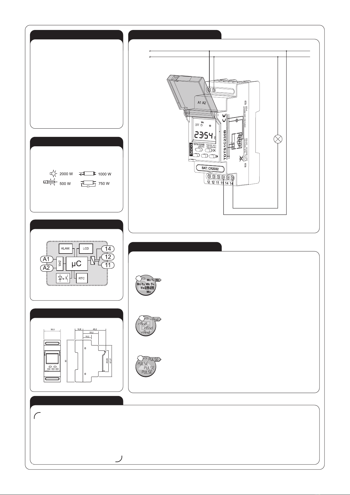
TECHNICAL DATADESCRIPTION
Power supply terminals: A1, A2
Input rated voltage: 230 V AC (-15 ÷ +10 %)
Nominal frequency: 50 / 60 Hz
Rated power consumption: 1,60 W /17 VA 1,50 W /3 VA
Number of channels: 1
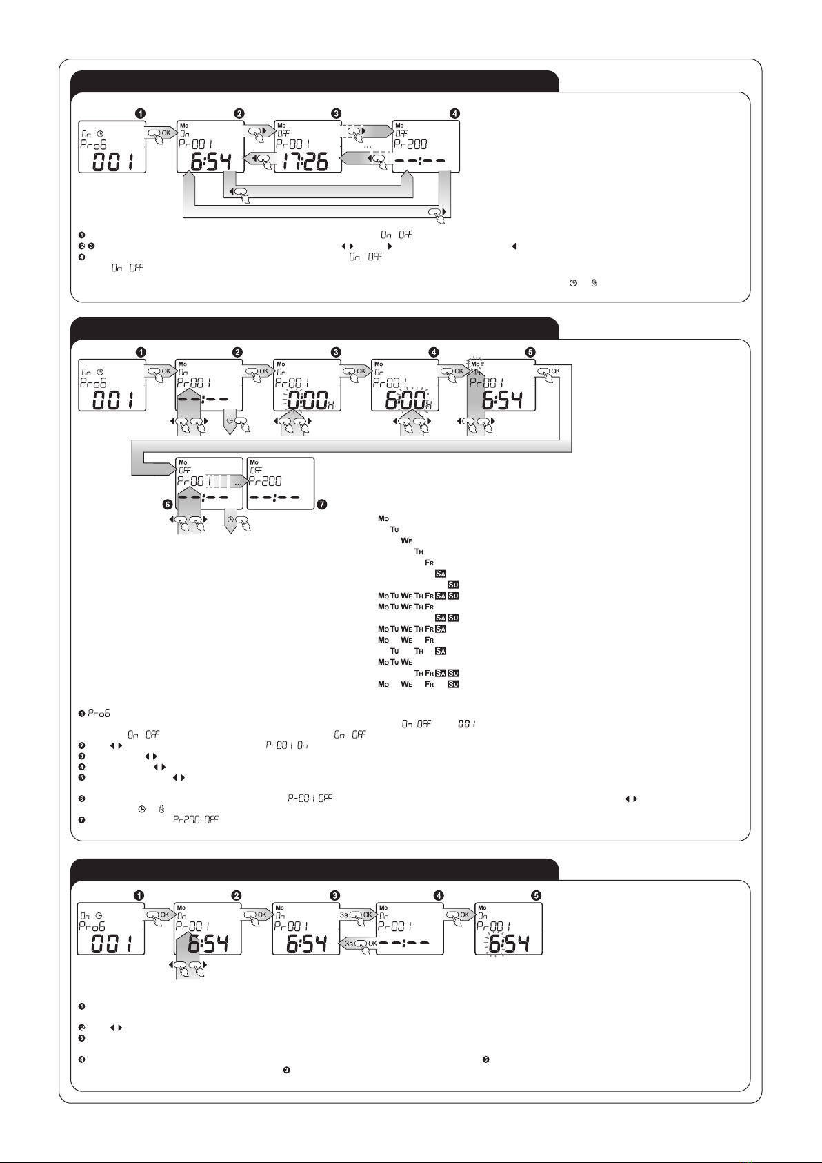
Program quantity: 400 (200 On/Off pairs)
Program: daily, week’s
Operating modes: manual, automatic, random, impulse
Change of season summer/ winter: automatic, manual
Accuracy of time measurement: max ±1 s / 24 h at temp. 25 °C
Time of clock maintenance: 3 years
Time of programme maintenance: 10 years
Receiver input (supply) terminals: 11, 12, 14
Output relay parameters: 1 NO/NC-16 A/250 V AC1 4000 VA
Number of terminal clamps: 8
Section of connecting cables: 0,2 ÷ 2,50 mm2
Ambient temperature range: -20 ÷ +60 oC
Operating position: freely
Mounting: rail TH 35 (EN 60715)
Protection degree: IP20 (EN 60529)
Overvoltage category: II
Pollution degree: 2
Dimensions: double-modular (35 mm) 90 x 35 x 66 mm
Weight: 0,140 kg
Reference standards: EN 60730-1; EN 60730-2-7
EN 61000-4-2,3,4,5,6,11
FEATURES
• week’s cycle control in dependence of
the current hour,
• double-module casing with a protec-
tion flap,
• many programmes enabling various
applications,
• mounted on TH 35 rail.
Digital control time switches
TDTS1C230B are used to realise the
time functions in automation and control
systems. Weekly programmers realise
output relay control operations accord-
ing to program adjustments (day, time).
The device depending on its type has
some additional functions e.g., a random
function, which can be used to simulate
presence, a control input function, which
is used to change the operating mode of
a system by means of an external push-
button. The design of the casing allows
the system to be mounted on a TH-35rail
and eventually to seal the device. The
design of the system provides a battery
back-up system for all adjustments in
case of no voltage supply.
In order to protect the battery during
storage, the TDTS1C230B series pro-
grammers have a default setting, the
so-called storage mode in which the
battery power consumption is limited
to a minimum.
The device should be connected to
a singlephase system according to
current standards. The device con-
nections will be described in this
manual. Only qualied electricians
are allowed to mount, connect and
adjust the device. It is necessary to read this
manual and know the unit functions before the
device mounting. Do not disassembly the device
casing or you will lose any warranty rights and ex-
pose yourself to the electric shock hazard. Before
mounting operation make sure of disconnecting
the connection wires from the electric network.
Use a cross-head screwdriver of 3.5 mm diam-
eter to mount the device. The relay should be car-
ried, stored and used in an appropriate way. Do
not mount the device in case of any device parts
lack, damage or deformation. In case of malfunc-
tion please notify the manufacturer.
CAUTION
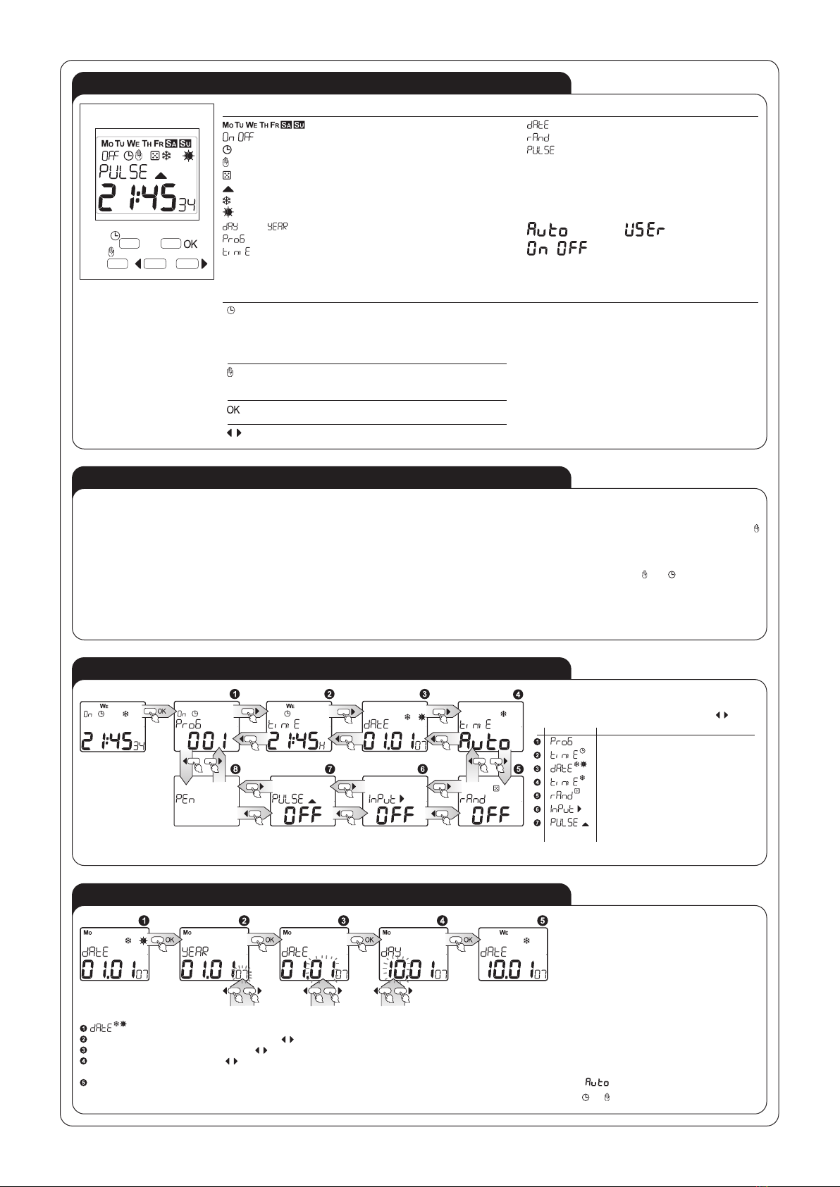
APPEARANCE
Winter time
Summer time
Random mode
Manual mode
Automatic mode
Week’s day
Relay state
Info eld
Current time
(gg:mm:ss)
Power terminals
(A1, A2)
LCD display
Replaceable battery
Control buttons
Relay output terminals
(12, 12, 11, 11, 14, 14)
Do not dispose of this device with other
waste! In order to avoid harmful effects
on the environment and human health,
the used device should be stored in
designated areas. For this purpose, you
can dispose of household waste free of
charge and in any quantity to a collection
point set up, as well as to the shop when
you buy new equipment.