TECshow GREY II 8 User manual

P. 1
| Tecshow Grey II 8
GREY II 8
Analog mixer - 8 Mic/line inputs +
1 stereo channel
USER MANUAL / MANUAL DE USUARIO
PLEASE READ THE INSTRUCTIONS CAREFULLY BEFORE USE
POR FAVOR LEA LAS INSTRUCCIÓNES ANTES DE USAR

P. 2
Tecshow Grey II 8 |
Grey II 8
Analog mixer - 8 Mic/line inputs + 1 stereo channel
Grey II 8 is the second generation of Grey mixers,
that features 8 Mic/line inputs with balanced XLR/
TRS connectors, 1 stereo input, 4-band equaliza-
tion per channel and a mp3 player with USB port.
The mixer also sports 1 auxiliary input/output, 16
types of adjustable delays, phantom power for all
its inputs and a general 7-band stereo equalization.
Grey II 8 stands out due to the quality of its low
noise preampliers that deliver exceptional sound
clarity with strong anti-interference ability, the
quality of its sliding faders and its solid construc-
tion, providing a quality alternative for small scale
applications.
Specications
General
• Mono Channels: 8
• Stereo Channels: 1
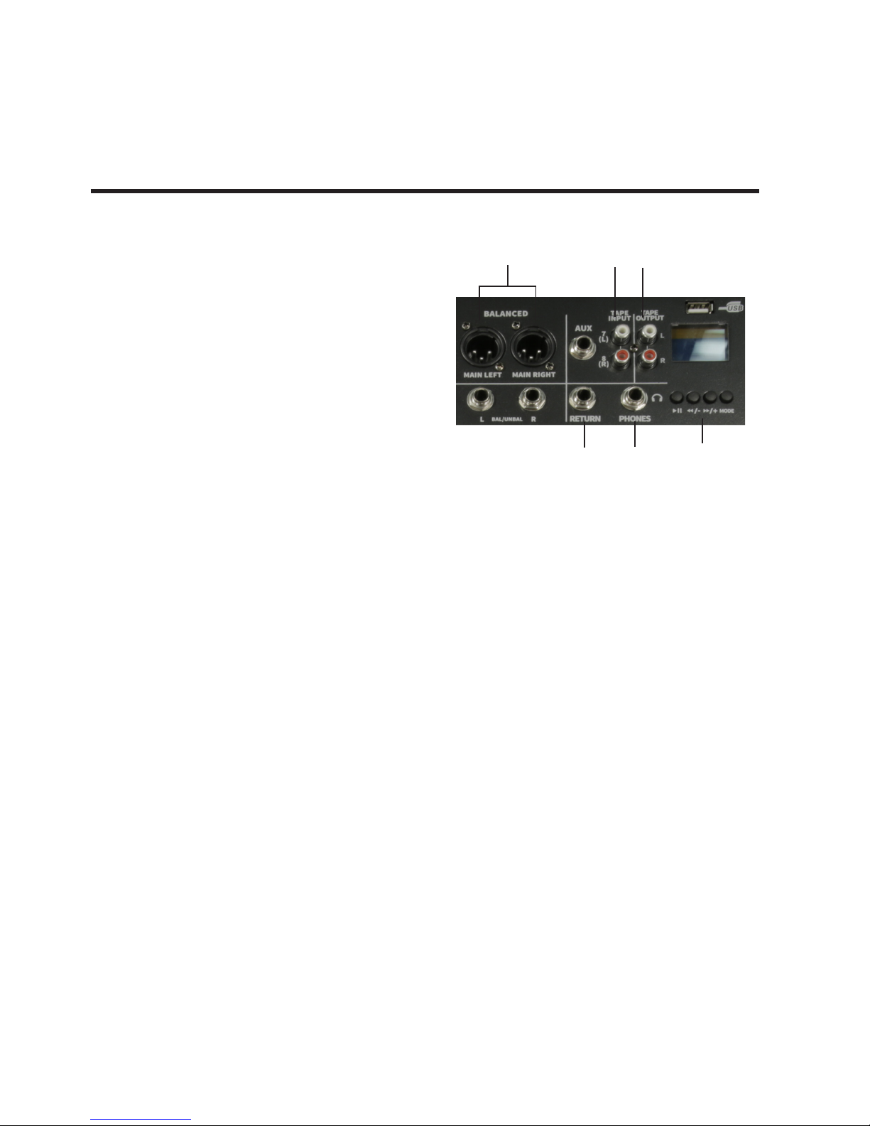
• Output connectors: 2 XLR & 2 TRS 1/4" Jacks
• Maximum levels: Mic: 30dBu / Line: 21dBu /
Stereo: 22dBu
• Input sensitivity: Mic: -60dB / Stereo:-40dB / FX
Send/Return:-20dB
• THD: <0.007%, +4 dBu @ 1KHz, unity gain
• Gain Control: -60dB~-20dB
• Input impedance:
- Mic: 4.7Ohm
- Line: >10KOhm
• Crosstalk: <-82dBu
• Earphone output power: 500-800mW
• Output impedance: < 120-Ohm
• Signal-to-Noise ratio: -80dB
• Frequency Response // Mic Input to main out-
put: +0,-1 dB, <10Hz to 80kHz, +0,-3 dB, <10Hz to
120kHz
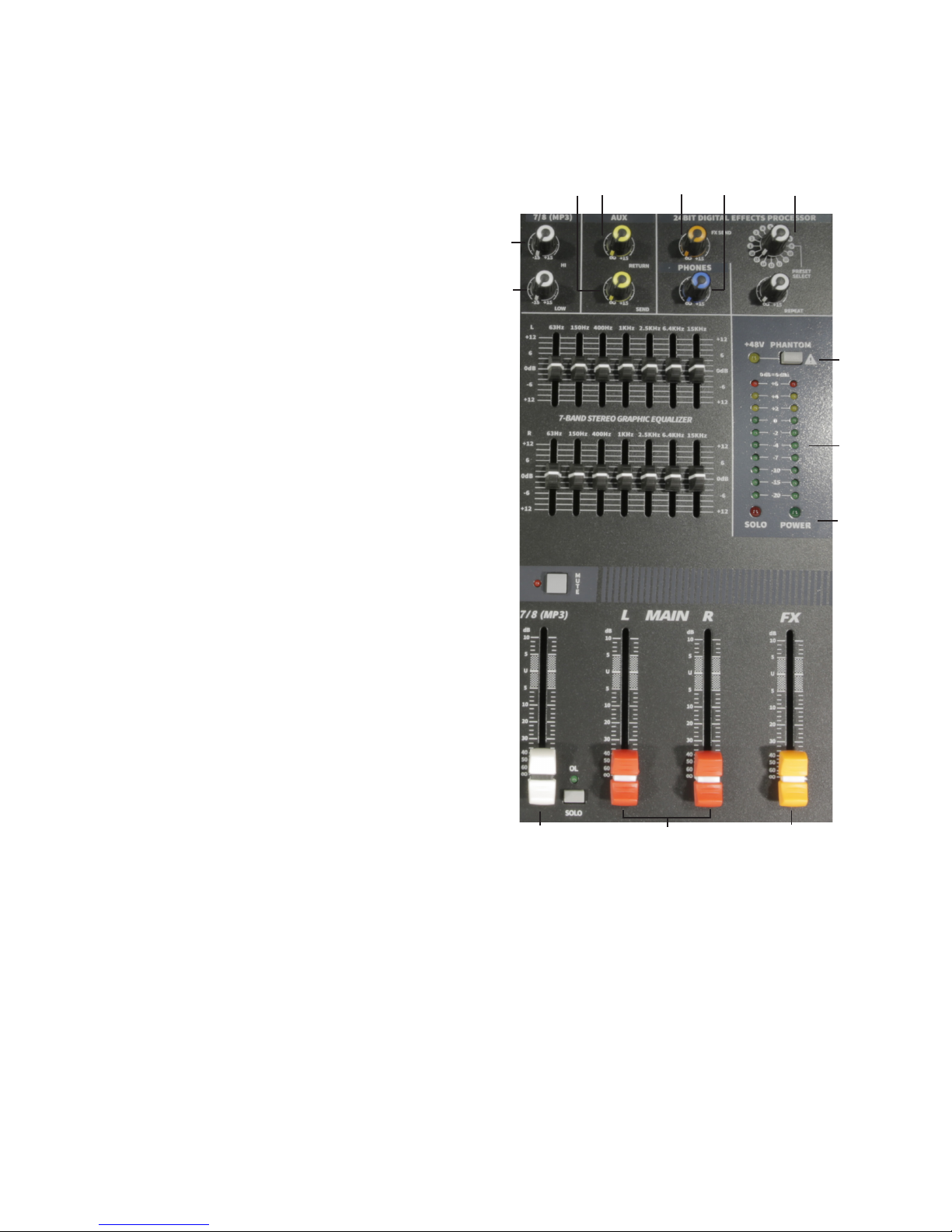
• 2 x 7 graphic equalizer
• Max output level: 22dBu
• +48V phantom power
• 1 auxiliar output
• 16 built-in HQ delay eects
• MP3 player with USB port
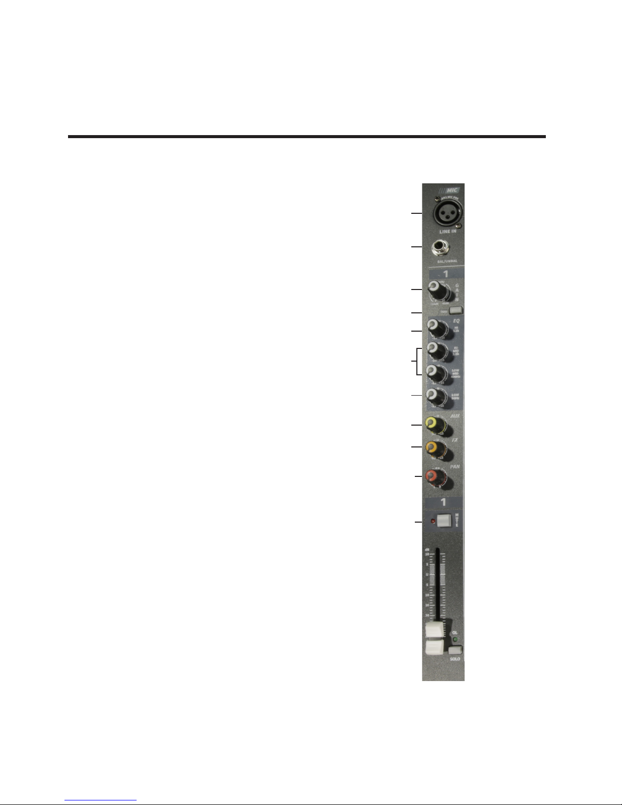
Per channel
• Mic Input: Electronically balanced XLR
• Line Input: TRS 1/4" Jack
• Stereo inputs: 2 RCA
• Equalization - mono:
- HF: 12KHz ± 15dB
- HMF: 2.5KHz ± 15dB
- LMF: 400Hz ± 15dB
- LF: 80Hz ± 15dB
• Equalization - stereo:
- HF: 12KHz ± 15dB
- LF: 80Hz ± 15dB
• Low-noise preamplier with strong anti-jam-
ming power
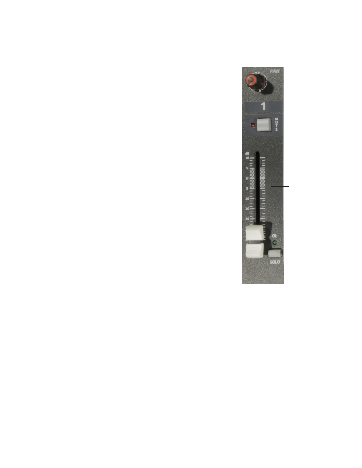
• Mute and solo selector
• Low Cut (75Hz)
• Peak indicator
Physical
• Dimensions: 410x455x100 mm. / 16.1x17.9x3.9
in.
• Weight: 7.5 Kg. / 16.5 Lbs.
Electrical
• Input voltage range: AC100–240V, 50-60Hz
• Power consumption: 30W
1. OVERVIEW
English version

P. 3
| Tecshow Grey II 8
English version
2. INPUT CHANNEL SECTION
1. Balance Input
Electronically Balanced inputs acceptable a stand-
ard XLR male connector. +48V Phantom Power
available on each input Mic socket. And this switch
is on Rear Phantom Power.
2. Line Input
The unbalanced Mic input is provided for the use
of a unbalanced mic and is designed to accept a
unbalanced high impedance input signal (This use
for connection Deck, Turntable, Keyboard ect.).
3. Gain Control
Adjusts input sensitivity from -60dB to -20dB with
the -20dB pad switch in the out position, and -40dB
to 0dB when the -20 dB pad switch is pushed.
4. Low Cut
The LOW CUT switch, 75Hz at a rate of 18dB per
octave.
5/6/7.4-Band Fixed - Frequency EQ
The stereo channels (9-16) have a 4-bandxed -
frequency equalization: LOW shelving at 80Hz, LOW
MlD peaking at 400Hz, HIMID peaking at 2.5kl-lz,
and Hl shelvingat 12kHz.Each of these lters pro-
vides up to 15dB of boost or cut. As with the mono
channels the circuit is at (no boost or cut)at the
center detent positions.
8. Aux Send
Use this control to set the level of signal from ex-
ternal stereo source and the main signal control is
recontrolled by STEREO or MONO section.
9. EFF
Use this control when you want to get eect sound
by adjustment of input signal. When you dont use
external source, digital delay will be working which
installed inside.
1
2
3
4
5
6
7
8
9
10
11

P. 4
Tecshow Grey II 8 |
English version
10. Pan
The pan control sends comtinuosly variable
amounts of the post fader signal to either the le
or right main busses. In the center position equal
amounts of signal are sent to the le and right
busses.
11. Mute
All output from the channel are enabled when the
MUTE switch released and muted when the switch
is down.
12. Channel Fader
This is function to adjust the volume of signal con-
nection in to each channel and adjust the volume of
output, together with master fader. Normal oper-
ation is at the O mark, providing 4dB of gain above
that point, if required.
13. OL (peak level indicator)
A red LED indicates a signal level at the insert return
point, pre master fader, It illuminates at approxi-
mately 5dB below clipping.
14. Solo
This lovable switch allows you to hear signals
through your head phones or control room without
having to route them to the main mix. You dont
even have to have the channels fader turned up.
Folks use solo in live work to preview channels
before they are letin to the mix, or to just check out
what a particular channel is up to any time during a
session. You can solo as many channels at a time as
you like.
10
12
11
13
14

P. 5
| Tecshow Grey II 8
English version
3. MASTER SECTION
15. Stereo Graphic Equalizer
2X7-band equalizer is provided for tone control over
each frequency, and for precise high quality sound
by nal tone control.
16. Phantom Power Switch/LED
Depressing this switch applies 48VDC across all
microphone input channels connectors for remote
powering of condenser microphones. The LED will
be runed on when phantom power start working.
17. Outputs Level Indicator
Condition on the way of operation. Therefore, you
can see output condition thru this master level
indication.
18. Power LED
The POWER LED will be turned on when start
working.
19. FX Level
Using by this control, you can adjust signal level of
echo repeat & exterior eect.
20. Output Main Fader
This is a master fader for adjustment for volume of
le/right output. Unity gain is the top their travel.
21. 9/10 VOLUME
Using by this control, you can adjust signal level of
9/10(mp3).
22. HI(high)
You can adjust of 9/10 channel. See the "6.HIGH".
23. Low
You can adjust of 9/10 channel. See the "8.LOW".
15
16
17
18

P. 6
Tecshow Grey II 8 |
English version
24. Aux Return
This is used of adjusting volume of echo AUX sound.
When return AUX singal to used jack.
25. Aux send
When this button is up, Post signal work as send
signal. When this button is down, post signal work
as eect singal.
26. FX Send
This is used for adjusting volume of echo fx sound,
when sending echo sound to send jack in eect
panel.
27. Phone
This is a single volume control sends the level to the
headphones and main monitors.
28. Eects Control
This is a 24BIT digital eects processor control.
23
22
25 24 26 27 28
16
17
18
21 20 19

P. 7
| Tecshow Grey II 8
English version
4. MIXER OUTPUT SECTION
29. Stereo output
These line level outputs connect the main mix to
the outside world. Connect them to the balanced
inputs of a power amplier or powered speakers.
30. Tape input Jack
This jack is to be connected with cassette deck
when playing back.
31. Tape output Jack
This jack is to be connected with cassette deck
when recording the mixed output.
32 MP3 Player
This MP3 input and playback.
33. Stereo AUX Returns & Sends
This can be used to connect all kinds of eects form
outside.
34. Phones Jack
This is used for monitoring them master signal and
individually monitoring each channel with PFL, L/R.
29 30 31
33 34 32

P. 8
Tecshow Grey II 8 |
English version
5. POWER SECTION
6. FAULT FINDING GUIDE
35. Power Switch
Push marked, when you want to operate, The LED
(SEE NO.20) will be turned on when working.
36. Power Jack
This is out of connect the power suplly jack.
Repaining a sound mixing console requires special-
ist, but basic fault nding is whitin the scope of any
user if a few badic rules followed.
• Get to know the block Diagram of your console.
• Get to know what each component in the sys-
tem is supposed to do.
• Learn where to look for common trouble spots.
The Block diagram is a representative sketch o fall
the components of the console; showing how they
connect together and how the signal ows through
the system. Once you have become familiar with
the various component have gained a valuable
understand of the internal structure of the console
and tracking down the problem by elimination.
• Swap input connections to check that the
source is really present. Check both Mic and
Line inputs.
• Eliminate sections of the channel by using
the insert point to re-route the signal to other
inputs that are konbs to be working.
• Route channels to dierent outputs or to aux
sends to identify problems on the master sec-
tion.
• Compare a suspect channel with an adjacent
channel which had been set up identically. Use
PFL to monitor the signal in each section.
35 36

P. 9
| Tecshow Grey II 8
English version
7. CAUNTIONS ON INSTALLATION
Please take care of the following points for installa-
tions.
1. Install this product at place of good ventilation
and keep a interval over 30cm from the other
objects.
2. Install this product at rear side for non-touching
of somebody, if possible and avoid an installa-
tion of a aisle & the front side of the stage.
3. Cause an obstacle and an drop of product from
the vibration of speaker, if you put this product
one speaker for a long time.
4. Avoid strong or using product in condition of
excessive heat or cold, or in position where it is
likely to be subject to vibration, dust or mois-
ture.
5. Connect the plug into an outlet by the check
of power source "AC 220V" of the installation-
place.
6. Install the speaker more front side than the
used mic and for away from mic, if possible.
7. Insert a plug of cord closely into the speaker
jack at the speaker connection.
8. Clean this product by using so dry cloth &
poly-wax.

P. 1 0
Tecshow Grey II 8 |
English version
8. HOW TO OPERATE
7. INSTALLATION
1. Above all, it is necessary to conrm power
voltage.
2. Make sure this appliance power switch is o
when connecting the plug of power cord with
outlet.
3. Set easy controls to the positions stated belows
to avoid lord blasts, Loud blasts may couse
damage for your speaker system or you rears
when you are wearing headphone. Master fad-
ers L/R, Sub faders AUX, Eect fader and Each
channel faders.
• Gain control: Turn to the le completely.
• Hi, Mid, Low: Turn to the center position.
• Aux 1-2 & Eect control: Turn to the le com-
pletely.
• Pan control: Turn to the center position.
• Set other turn to the le completely.
4. Push power switch marked(1), then the LED will
be turned on when start working.
5. Set Master faders L-R to the position between
min & mid, aer working.
6. Set a certain Channel faders which you want
to use to the position between min and mid.
Aer that, Connect input section with external
source.
7. To make sound thur external sources, turn the
Gain control to the right.
8. Adjust tone controls in accordance with your
taste.
9. Adjust between Eect fader control towards
max from min & eect control to the right,
when you want to get echo eect a certain
channel, aer set a certain channel, adjust
delay control & repeat control, then you can get
various echo eect sound.
FIGURE 1
UNBALANCES 1/4" PLUG TIP: POSITIVE (hot+)
SLEEVE GROUND (shield)

P. 11
| Tecshow Grey II 8
English version
FIGURE 1-1
FIGURE 1-2
FEMALE 3 PIN CONNECTOR 2. HOT +
1. GROUND (shield)
3. GOLD -
STEREO SHIELDED CABLE

P. 12
Tecshow Grey II 8 |
English version

P. 13
| Tecshow Grey II 8
Versión Español
Grey II 8
Mezcladora analógica conable de 8 entradas Mic/
Línea y 1 estéreo
Grey II 8 es la segunda generación de mezcladores
Grey, que cuenta con 8 entradas mic/línea con con-
exiones balanceadas XLR/TRS, 1 entrada estéreo,
ecualizador de 4 bandas y reproductor mp3 con
puerto USB. La consola provee 1 salida auxiliar,
16 tipos de delays regulables, potencia phantom
para todas sus entradas y una ecualización gener-
al estéreo de 7 bandas. Grey II 8 se destaca de la
media por la calidad de sus preamplicadores de
bajo ruido que entregan una claridad de sonido
excepcional con grandes cualidades anti interferen-
cia, por la calidad de sus faders deslizables y por su
sólida construcción, brindando así una alternativa
de calidad para aplicaciones de pequeña escala.
Especicaciones
General
• Canales mono: 8
• Canales estéreo: 1
• Conectores de salida: 2 XLR & 2 Plug TRS 1/4"
• Niveles máximos: Mic: 30dBu / Línea: 21dBu /
Estéreo: 22dBu
• Sensibilidad de entrada: Mic: -60dB/ Estére-
o:-40dB / FX Send/Return:-20dB
• THD: <0.007%, +4 dBu @ 1 KHz, unidad de
ganancia
• Control de ganancia: -60dB~-20dB
• Impedancia de entrada:
- Mic: 4.7Ohm
- Línea: >10KOhm
• Crosstalk: <-82dBu
• Potencia de salida - auriculares: 500-800mW
• Impedancia de salida: < 120Ohm
• Relación señal-a-ruido : -80dB
• Respuesta de frecuencia / Entrada de micró-
fono a salida main: +0,-1 dB, <10Hz a 80kHz,
+0,-3 dB, <10Hz a 120kHz
• Ecualizador gráco 2 x 7
• Nivel máximo de salida: 22dBu
• +48V potencia phantom
• 1 salida auxiliar
• 16 FX de delay integrados
• Reproductor MP3 con puerto USB
Por canal
• Entrada de micrófono: XLR electrónicamente
balanceado
• Entrada de línea: TRS 1/4" Plug
• Entradas estéreo: 2 RCA
• Ecualización - mono:
- HF: 12KHz ± 15dB
- HMF: 2.5KHz ± 15dB
- LMF: 400Hz ± 15dB
- LF: 80Hz ± 15dB
• Ecualización - estéreo:
- HF: 12KHz ± 15dB
- LF: 80Hz ± 15dB
• Preamplicador de bajo ruido
• Selector de silencio y solo
• Low Cut: Corte de bajas frecuencias (75Hz)
• Indicador de picos
Físico
• Dimensiones: 410x455x100 mm. /
16,1x17,9x3,9 pulg.
• Peso: 7,5 Kg. / 16,5 Lbs.
Eléctrico
• Rango de voltaje de entrada: AC100–240V,
50-60Hz
• Consumo de potencia: 30W
1. DESCRIPCIÓN

P. 14
Tecshow Grey II 8 |
Versión Español
2. CANALES DE ENTRADA
1. Entrada balanceada
Las entradas electrónicamente balanceadas son
compatibles con los conectores macho XLR es-
tándar. Cada entrada de micrófono cuenta con
alimentación fantasma de +48 V. El interruptor se
ubica en la sección principal.
2. Line Input (entrada de línea)
Conecte micrófonos no balanceados en esta en-
trada de línea no balanceada que es compatible
para recibir señal de entrada de alta impedancia no
balanceada (para plataformas de conexión, toca-
discos, teclados, etc).
3. Gain (control de ganancia)
Para regular la sensibilidad de entrada entre -60 dB
y -20 dB, tire el atenuador PAD hacia afuera. Para
regularla entre -40 dB y 0 dB, presione el atenuador
y luego gírelo.
4. Corte de graves
Interruptor de corte de graves, 75 Hz a 18 dB por
octava.
5/6/7 EQ (ecualizador de frecuencia
ja de 4 bandas)
Los canales estéreo (9-16) cuentan con ecualización
de frecuencia ja de 4 bandas: meseta de bajos en
80 Hz, meseta de medios bajos en 400 Hz (pico),
meseta de medios altos en 2,5 kHz y meseta de
altos en 12 kHz. Cada uno de estos ltros ofrece 15
dB de amplicación o atenuación. Como los cana-
les mono, el circuito es plano en posición central.
8. Aux
Congure el nivel de señal de una fuente estéreo
externa mientras envía el control de señal principal
a la sección STEREO o MONO.
9. EFF
Genere efectos de sonido regulando la señal de en-
trada. Si no emplea una fuente externa, se utilizará
el retardo digital integrado.
1
2
3
4
5
6
7
8
9
10
11

P. 15
| Tecshow Grey II 8
Versión Español
10. Pan
Utilice el control de pan para enviar señal post-
deslizador de forma continua a los buses princi-
pales izquierdos o derechos. Ajustado en posición
central, se enviará el mismo volumen de señal a los
buses derechos e izquierdos.
11. Mute
Todas las salidas de canal se silenciarán cuando se
active la opción MUTE.
12. Deslizador de canal
Regule el volumen de señal de cada canal y el
volumen de salida junto con el deslizador maestro.
Suele utilizarse en posición "0", pero de ser necesa-
rio provee hasta 4 dB de ganancia.
13. OL (indicador de pico)
Un indicador LED rojo señala el nivel de señal en el
punto de retorno del deslizador maestro. Se ilumi-
na aproximadamente 5 dB por debajo del nivel de
saturación.
14. Solo
Esta tecla le permite escuchar la señal con auricu-
lares o en una sala de control sin tener que enviarla
a la mezcla principal. Tampoco es necesario regular
el deslizador del canal. SOLO se utiliza normal-
mente en trabajos en vivo para tener una vista pre-
via de los canales antes de incluirlos en la mezcla
o para vericar el estado de un canal durante una
sesión. Puede utilizar esta función en la cantidad
de canales que necesite.
10
12
11
13
14

P. 1 6
Tecshow Grey II 8 |
Versión Español
3. SECCIÓN PRINCIPAL
15. Ecualizador gráco estéreo
Utilice el ecualizador de bandas 2x7 para ajustar
todas las frecuencias de tonos y para un control
preciso del sonido.
16. Phantom (alimentación fantasma)
Utilice esta tecla para suministrar 48 V/CC a todos
los canales de entrada de los micrófonos y así
habilitar la alimentación externa de los micrófonos
condensadores. El indicador LED se iluminará cuan-
do esté activa la alimentación fantasma.
17. Indicador del nivel de salida
Los niveles de salida están sujetos a la operación
de los canales izquierdo y derecho. El usuario podrá
ver el estado del nivel de salida a través del indica-
dor de nivel.
18. Power
El indicador se iluminará cuando se encienda la
consola.
19. Deslizador FX
Regule el nivel de señal del eco, la repetición y efec-
tos exteriores.
20. Deslizadores main L/R
Regule el volumen de las salidas izquierdas/dere-
chas con este deslizador maestro. Lleve el desliza-
dor hacia arriba para obtener ganancia unitaria.
21. VOLUMEN 9/10
Regule el nivel de señal de los archivos MP3 (9/10).
22. HI (frecuencias altas)
Regule la frecuencia del canal 9/10. Para más infor-
mación, vea el punto 6. HIGH.
15
16
17
18

P. 17
| Tecshow Grey II 8
Versión Español
23. LOW (frecuencias bajas)
Regule la frecuencia del canal 9/10. Para más infor-
mación, vea el punto 8. LOW.
24. Aux Return
Utilice el retorno auxiliar para regular el volumen
de eco de un sonido auxiliar.
25. Aux send
Si gira la perilla hacia la derecha, la señal "post"
funcionará como señal de envío. Si gira la perilla
hacia la izquierda, la señal "post" funcionará como
señal de efecto.
26. FX Send
Utilice el envío de FX para regular el volumen de
eco de un efecto de sonido, si se envía mediante el
conector SEND del panel de EFFECT.
27. Phone
Control único de volumen que envía señal a los
auriculares y monitores principales.
28. Control de efectos
Procesador de efectos digitales de 24 bits.
23
22
25 24 26 27 28
16
17
18
21 20 19

P. 18
Tecshow Grey II 8 |
Versión Español
4. CONTROLES DE SALIDA
29. Salida Stereo
Estas salidas de nivel de línea conectan la mezcla
principal con el mundo exterior. Conéctelas a las
entradas balanceadas de un amplicador de poten-
cia o de un altavoz activo.
30. Tape input
Utilice esta entrada para conectar un reproductor
de casetes durante la reproducción.
31. Tape output
Utilice esta salida para conectar un reproductor de
casetes durante la grabación de salidas mezcladas.
32. Reproductor MP3
Entrada y reproducción de archivos MP3.
33. AUX Returns & Sends
Utilice el envío y retorno de auxiliares estéreos para
conectar cualquier tipo de efectos externos.
34. Conector Phones
Escuche la señal principal de salida y monitoree
los diferentes canales con las funciones PFL, L/R
(izquierda/derecha).
29 30 31
33 34 32

P. 1 9
| Tecshow Grey II 8
Versión Español
5. SECCIÓN ELÉCTRICA
35. Interruptor de encendido/
apagado
Presione la tecla para encender el equipo. El indica-
dor LED (ver nro. 20) se iluminará.
36. Power Jack
Esto está fuera de conectar el conector de alimen-
tación de energía
35 36

P. 2 0
Tecshow Grey II 8 |
Versión Español
6. RESOLUCIÓN DE PROBLEMAS
7. INSTALACIÓN
A continuación encuentra una guía de problemas
habituales que el usuario puede solucionar con
facilidad. Sin embargo, si el problema persiste y
necesita reparar su consola, póngase en contacto
con el servicio técnico autorizado.
• Familiarícese con el diagrama de bloques de su
consola.
• Conozca los componentes del sistema y su
función.
• Aprenda a localizar las zonas con problemas
habituales.
El diagrama de bloques es un boceto representati-
vo de todos los componentes de la consola, donde
se muestra cómo se conectan los componentes y
cómo uye la señal por el sistema. Una vez que se
Durante la instalación del equipo preste atención a
los siguientes puntos:
1. Coloque el equipo en un lugar con buena venti-
lación y mantenga una distancia mínima de 30
cm de otros objetos.
2. Instale el equipo lejos del alcance de las perso-
nas. Evite colocarlo en pasillos, la parte frontal
de un escenario o zonas muy transitadas.
3. Instale el equipo sobre una supercie plana y
nivelada para evitar vibraciones, deslizamien-
tos y posibles caídas.
4. Evite utilizar el equipo en condiciones de calor
o frío extremos, y manténgalo protegido del
polvo y la humedad.
5. Verique que el rango de voltaje de entrada
coincida con el requerido por la consola.
6. Utilice el equipo lejos de altavoces y micró-
haya familiarizado con los distintos componentes,
habrá comprendido la estructura interna de la con-
sola y podrá descartar problemas fácilmente.
• Intercambie las conexiones de entrada para
comprobar que la fuente esté bien conectada.
Corrobore las entradas de línea y de micrófono.
• Utilice el punto de inserción para redirigir la
señal a otras entradas que sepa que funcionan
correctamente con el n de eliminar secciones
del canal.
• Envíe los canales a distintas salidas o envíos
auxiliares para identicar problemas en la sec-
ción principal o master.
• Compare el canal que considera defectuoso
con un canal contiguo congurado de la misma
forma. Utilice el PFL para monitorear la señal
en cada sección.
fonos.
7. Inserte el enchufe del cable en la toma del
altavoz.
8. Limpie la consola con un paño seco y un pro-
ducto a base de cera.
This manual suits for next models
1
Table of contents
Languages:
Other TECshow Music Mixer manuals
Popular Music Mixer manuals by other brands

Broadcast Tools
Broadcast Tools SUM-4 Installation and operation manual

Rodec
Rodec MX180 MKIII operating instructions

airinspace
airinspace RHEA Satellite user manual

ALLEN & HEATH
ALLEN & HEATH GLD CHROME EDITION user guide

Ross
Ross Wheatstone D-Series setup sheet

GRASS VALLEY
GRASS VALLEY INDIGO AV MIXER quick start guide