teenage engineering oplab User manual

8/5/2019 teenage engineering – oplab module guide
https://teenage.engineering/guides/op-z/modules/oplab 1/5
oplab
module
connectivity
module for OP-Z user guide
ガイド
v.1.0
notice
.
read
this
first
.
never connect the 3.5mm plugs coming from module
connectors to any mic or line-level audio equipment
such as inputs or outputs on sound cards, mixers and
synthesizers. for example:
phantom power coming from a mic-input on a sound
cards could destroy the ports on the oplab module.
•
the voltage coming from oplab moudule's cv or gate
could damage a line input or line output stage.
•
FCC ID: Z23012AIC: 9915A-012A
this device complies with part 15 of the fcc rules.
operation is subject to the following two conditions: (1)
this device may not cause harmful interference, and (2)
this device must accept any interference received,
including interference that may cause undesired
operation.this device complies with industry canada
licence-exempt rss standard(s). operation is subject to
the following two conditions: (1) this device may not
cause interference, and (2) this device must accept any
interference, including interference that may cause
undesired operation of the device.
warranty: the oplab module is fully factory tested and
comes with a 12 month (from purchase date) warranty.
this does not include malfunction due to misuse of the
device, such as being dropped, crushed or use in an
application of inappropriate voltages to the device
’
s
connectors or improperly designed or executed
modifications.store small parts out of the reach of
children and infants. if accidentally swallowed, contact a
doctor immediately. make sure to avoid touching
sensitive components and be aware of static discharge
(esd).
the general guarantee policy does not cover esd
damaged products due to improper handling. the
warranty does not cover shipping charges. make sure
to read the terms & conditions on our website.
what
'
s
in
the
box
check that the following items are
included when you open the box
oplab module. user's guide. midi adapter cable.
8/5/2019 teenage engineering – oplab module guide
https://teenage.engineering/guides/op-z/modules/oplab 2/5
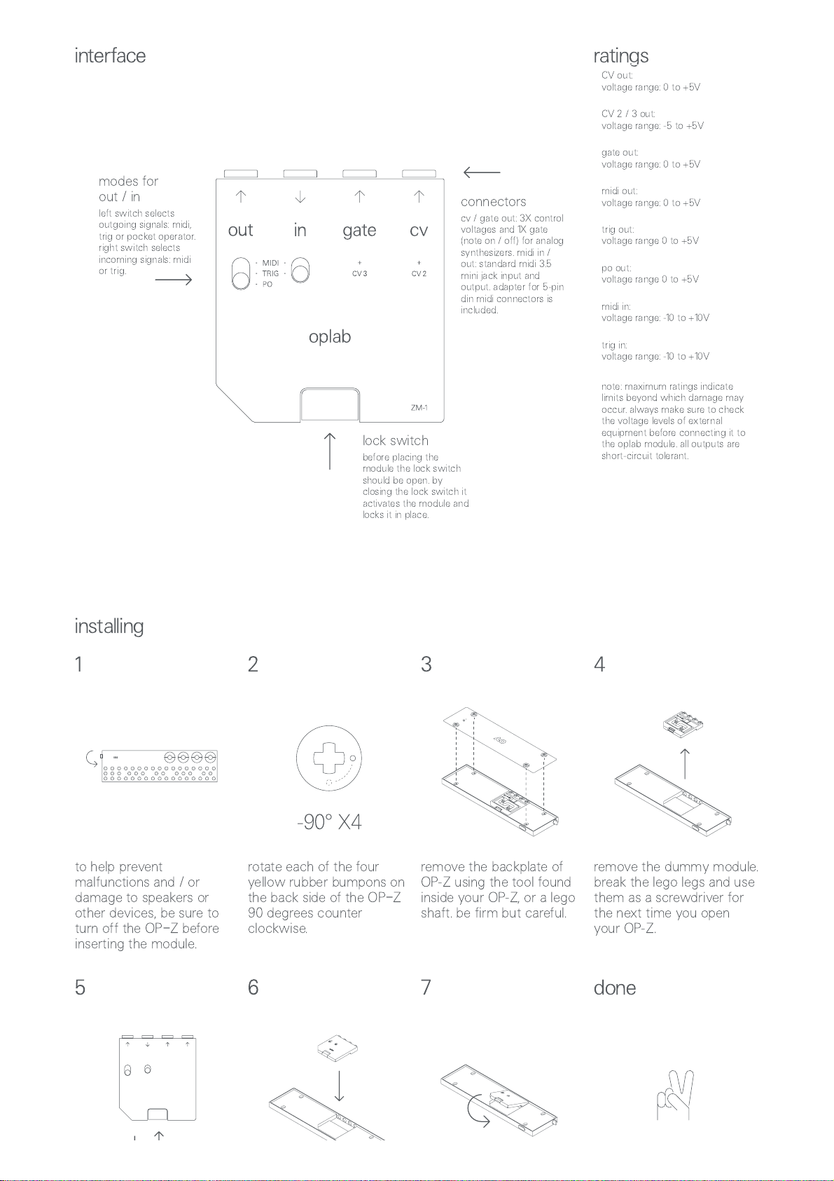
interface ratings
connectors
cv / gate out: 3X control
voltages and 1X gate
(note on / off) for analog
synthesizers. midi in /
out: standard midi 3.5
mini jack input and
output. adapter for 5-pin
din midi connectors is
included.
lock switch
before placing the
module the lock switch
should be open. by
closing the lock switch it
activates the module and
locks it in place.
modes for
out / in
left switch selects
outgoing signals: midi,
trig or pocket operator.
right switch selects
incoming signals: midi
or trig.
installing
1 2 3 4
-90° X4
to help prevent
malfunctions and / or
damage to speakers or
other devices, be sure to
turn off the OP
–
Z before
inserting the module.
rotate each of the four
yellow rubber bumpons on
the back side of the OP
–
Z
90 degrees counter
clockwise.
remove the backplate of
OP-Z using the tool found
inside your OP-Z, or a lego
shaft. be firm but careful.
remove the dummy module.
break the lego legs and use
them as a screwdriver for
the next time you open
your OP-Z.
5 6 7
done
!
CV out:
voltage range: 0 to +5V
CV 2 / 3 out:
voltage range: -5 to +5V
gate out:
voltage range: 0 to +5V
midi out:
voltage range: 0 to +5V
trig out:
voltage range 0 to +5V
po out:
voltage range 0 to +5V
midi in:
voltage range: -10 to +10V
trig in:
voltage range: -10 to +10V
note: maximum ratings indicate
limits beyond which damage may
occur. always make sure to check
the voltage levels of external
equipment before connecting it to
the oplab module. all outputs are
short-circuit tolerant.
8/5/2019 teenage engineering – oplab module guide
https://teenage.engineering/guides/op-z/modules/oplab 3/5
!
make sure the module is off
by pressing the lock switch
toward the top connectors.
make sure the artwork is
facing toward you and that
the angled corner is on the
left hand side.
insert the top part first
–
the
jacks should go through the
holes on the top side of the
OP-Z. once inserted, pull
down the lock switch and
put back the OP-Z back
plate.
now you're done and the
oplab module is ready to be
used.
regularly check the website
for the latest ZM-1 firmware:
teenage.engineering/downloads
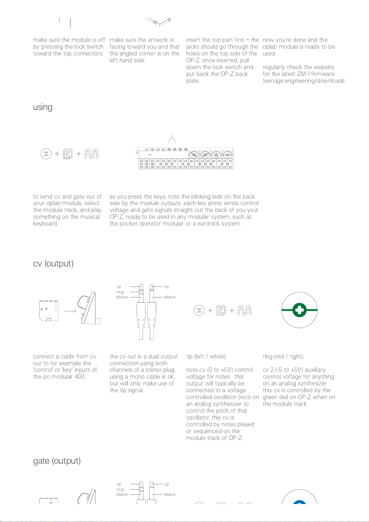
using
to send cv and gate out of
your oplab module, select
the module track, and play
something on the musical
keyboard.
as you press the keys, note the blinking leds on the back
side by the module outputs. each key press sends control
voltage and gate signals straight out the back of you your
OP-Z, ready to be used in any modular system, such as
the pocket operator modular or a eurorack system.
cv
(
output
)
tip
ring
sleeve
tip
sleeve
connect a cable from cv
out to for example the
'control' or 'key' inputs of
the po modular 400.
the cv out is a dual output
connection using both
channels of a stereo plug.
using a mono cable is ok,
but will only make use of
the tip signal.
tip (left / white).
note cv (0 to +5V) control
voltage for notes. this
output will typically be
connected to a voltage
controlled oscillator (vco) on
an analog synthesizer to
control the pitch of that
oscillator. this cv is
controlled by notes played
or sequenced on the
module track of OP-Z.
ring (red / right).
cv 2 (-5 to +5V) auxiliary
control voltage for anything
on an analog synthesizer.
this cv is controlled by the
green dial on OP-Z when on
the module track.
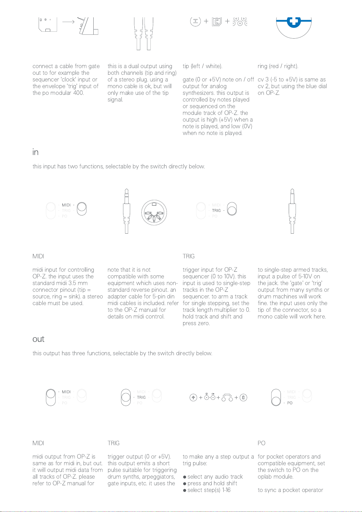
gate
(
output
)
tip
ring
sleeve
tip
sleeve
8/5/2019 teenage engineering – oplab module guide
https://teenage.engineering/guides/op-z/modules/oplab 4/5
connect a cable from gate
out to for example the
sequencer 'clock' input or
the envelope 'trig' input of
the po modular 400.
this is a dual output using
both channels (tip and ring)
of a stereo plug. using a
mono cable is ok, but will
only make use of the tip
signal.
tip (left / white).
gate (0 or +5V) note on / off
output for analog
synthesizers. this output is
controlled by notes played
or sequenced on the
module track of OP-Z. the
output is high (+5V) when a
note is played, and low (0V)
when no note is played.
ring (red / right).
cv 3 (-5 to +5V) is same as
cv 2, but using the blue dial
on OP-Z.
in
this input has two functions, selectable by the switch directly below.
MIDI
midi input for controlling
OP-Z. the input uses the
standard midi 3.5 mm
connector pinout (tip =
source, ring = sink). a stereo
cable must be used.
note that it is not
compatible with some
equipment which uses non-
standard reverse pinout. an
adapter cable for 5-pin din
midi cables is included. refer
to the OP-Z manual for
details on midi control.
TRIG
trigger input for OP-Z
sequencer (0 to 10V). this
input is used to single-step
tracks in the OP-Z
sequencer. to arm a track
for single stepping, set the
track length multiplier to 0.
hold track and shift and
press zero.
to single-step armed tracks,
input a pulse of 5-10V on
the jack. the 'gate' or 'trig'
output from many synths or
drum machines will work
fine. the input uses only the
tip of the connector, so a
mono cable will work here.
out
this output has three functions, selectable by the switch directly below.
MIDI
midi output from OP-Z is
same as for midi in, but out.
it will output midi data from
all tracks of OP-Z. please
refer to OP-Z manual for
TRIG
trigger output (0 or +5V).
this output emits a short
pulse suitable for triggering
drum synths, arpeggiators,
gate inputs, etc. it uses the
to make any a step output a
trig pulse:
select any audio track•press and hold shift•select step(s) 1-16•
PO
for pocket operators and
compatible equipment, set
the switch to PO on the
oplab module.
to sync a pocket operator

8/5/2019 teenage engineering – oplab module guide
https://teenage.engineering/guides/op-z/modules/oplab 5/5
details on midi
implementation. tip of the connector, so a
mono cable is fine. press jump•press value key 0•release shift•press play and verify
led activity
•
to an OP-Z:
connect oplab out with
PO input (left side)
•
set PO to SY2 or SY3•press play on PO•press play on OP-Z•
connector
overview
the CV interface sends on MIDI channel 1 and listens to channel 1 and 15.
jack cv gate in out
mode
– –
midi trig po midi trig
tip cv (note) gate source trigger sync source trigger
ring cv 2 cv 3 sink
– –
sink
–
sleeve ground ground
–
ground ground ground ground
Popular Control Unit manuals by other brands

Espressif Systems
Espressif Systems ESP32-WROOM-32UE user manual

Civacon
Civacon NV4000 Installation & maintenance manual

Hansen
Hansen MCV Installation, service instructions & parts

Wilo
Wilo RS485 Installation and operating instructions

SICK
SICK CDB650 operating instructions

Zurn Wilkins
Zurn Wilkins 4-ZW207 Installation, Troubleshooting, Maintenance Instructions


