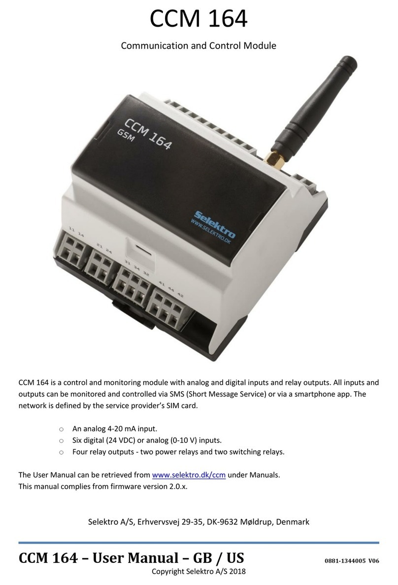
Selektro CCM 164 User manual

CCM 164 –User Manual –GB / US 0881-1344005 V09
Copyright Selektro A/S 2022
CCM 164
Communication and Control Module
CCM 164 is a control and monitoring module with analog and digital inputs and relay outputs. All inputs and
outputs can be monitored and controlled via SMS (Short Message Service) or via a smartphone app. The
network is defined by the service provider’s SIM card.
oAn analog 4-20 mA input.
oSix digital (12-24 VDC) or analog (0-10 V) inputs.
oFour relay outputs - 2 power relays and 2 switching relays.
oTwo power supply versions, 240Vac and 24VDC
The User Manual can be retrieved from www.selektro.dk/ccm under Manuals.
This manual complies from firmware version 2.1.x.
This manual complies from hardware version 5 and forward.
Selektro A/S, Erhvervsvej 29-35, DK-9632 Møldrup, Denmark

CCM 164 –User Manual –GB / UK
2
Contents
Description of the control lamps, buttons and SIM card .......................................................................... 5
Connection................................................................................................................................................. 7
Getting started .......................................................................................................................................... 8
Configuration............................................................................................................................................. 9
4.1. Module name .................................................................................................................................... 9
4.2. Language............................................................................................................................................ 9
4.3. Phone book...................................................................................................................................... 10
4.4. Locking (Security)............................................................................................................................. 11
Input and Output Definition.................................................................................................................... 13
5.1. Current input ................................................................................................................................... 13
5.2. Voltage input ................................................................................................................................... 13
5.3. Digital input ..................................................................................................................................... 14
5.4. Relay output .................................................................................................................................... 14
5.5. Bit Register....................................................................................................................................... 14
5.6. Clock module................................................................................................................................... 15
5.7. Message Inputs/Macros.................................................................................................................. 16
Rules between inputs and outputs.......................................................................................................... 17
6.1. Reaction rate for rules..................................................................................................................... 18
6.2. Extension of <condition> for rules .................................................................................................. 19
6.3. Extension of <Action> number for rules.......................................................................................... 20
6.4. Extension of <Action> options for Q and B ..................................................................................... 20
6.5. Relationships between several rules............................................................................................... 22
6.6. Significance of supply outages for rules and outputs...................................................................... 25
Read values.............................................................................................................................................. 26
7.1. Message Input/Macro histories ...................................................................................................... 27
Read Definitions ...................................................................................................................................... 28
Delete definition / set to default............................................................................................................. 29
Smart Functions................................................................................................................................... 30
10.1. Service information ..................................................................................................................... 30
10.2. Special functions.......................................................................................................................... 30
10.3. Supply outages ............................................................................................................................ 31
10.4. Supply Output Overload.............................................................................................................. 31
10.5. System management and information........................................................................................ 32
10.6. Configure outputs manually........................................................................................................ 35
Good to know… ................................................................................................................................... 36

CCM 164 –User Manual –GB / UK
3
11.1. Removing a PIN code from+ a SIM card ...................................................................................... 36
11.2. Manually unlocking the configuration......................................................................................... 36
11.3. Manual restart module................................................................................................................ 36
11.4. Language restrictions, SMS length (GSM 7 bit / Unicode 16 bit) ................................................ 36
11.5. Recommended configurations .................................................................................................... 37
Problem resolving (troubleshooting) .................................................................................................. 38
Overview of commands (short form) .................................................................................................. 40
13.1. General command definitions:................................................................................................ 40
Firmware update ................................................................................................................................. 48
Responsibility and guarantee .............................................................................................................. 51
15.1. Responsibility for CCM 164 and its use ....................................................................................... 51
15.2. Guarantee.................................................................................................................................... 51
Electrical specifications ....................................................................................................................... 52

CCM 164 –User Manual –GB / UK
4
Warning
Always read this User Manual prior to installation.
Installation and use must be in accordance with
applicable rules and good practice.
Warning
Persons with reduced physical capability, sensory or
mental status, must not use this product unless under
appropriate direct supervision or have been instructed
by a person responsible for their safety. Minors must
not use or play with this product.
Warning
The module is not suited for monitoring sensitive
factories or time-critical processes. GSM network
failures of disruptions in net power can affect safety
and monitoring reliability. Do not use OFF outputs to
implement safety-related functions for
systems/machines.
Warning
The module must not be placed in a dangerous
explosive area or in close proximity to medical
equipment.

CCM 164 –User Manual –GB / UK
5
Description of the control lamps, buttons and SIM card
Control lamps
STATUS
Constantly on
on
off
Module recently connected to the power
supply and backup battery is charging.
Slow long flashing
on
off
Module is initializing.
Slow flashing
on
off
Module is ready and everything is OK.
Quick flashing
on
off
There is an error. Refer to MODEM STATUS.
50% on
50% flashing
on
off
EEPROM Error.
Turned off
on
off
No supply voltage. If MODEM STATUS is
flashing the module is using the backup.
NET
STATUS
Slow flashing
on
off
MODEM is operational.
Fast flashing
on
off
Network not accessible.
Turned off
on
off
MODEM is turned off.
MODEM STATUS
Slow long flashing
on
off
MODEM is initializing.
Slow short flashing
on
off
Module is using backup. MODEM STATUS
LED is turned off.
Slow flashing
on
off
MODEM is ready with NET connection.
Two quick flashes
on
off
SIM card error.
Quick flashing
on
off
GSM network error.
Turned off
on
off
MODEM is turned off.
50% on/off flashing
on
off
Modem transmitting
NET STATUS
Flashes when the
MODEM is powered
ON.
OUTPUTS
Displays levels for the
4 relay outputs.
MODE
Used for confirmations
and unlocking.
SIM card
Refer to “0 SIM card”
Remember that the
card must not have a
PIN code.
STATUS
Flashes slowly when all
is OK. Flashes quickly
when the unit starts or
if there is an error. For
further details refer to
the table below.
MODEM STATUS
Flashes slowly when
the MODEM is ready.
For further details refer
to the table below.
INPUTS
Displays the digital value of
the 6 combined digital and
analog inputs.

CCM 164 –User Manual –GB / UK
6
Button
The MODE button beneath the cover can be used to unlock the module. Refer to “11.2.
Manually unlocking the configuration”.
SIM card
Newer versions of the CCM 164 hardware (V2) uses SIM card Nano 12.3 x 8.8 mm type and is
compatible with 1.8V and 3V SIM cards.
Older versions of the CCM 164 hardware (V1) uses SIM card Mini 85.6 x 53.98 mm type and is
compatible with 1.8V and 3V SIM cards.
Note : There must not be a PIN code on the SIM card.
Refer to “11.1. Removing a PIN code from+ a SIM card”.
Accessories
Stub antenna Planar antenna
•Stub antenna, order number: 0991-70010001
•Planar antenna, order number: 0991-70010003

CCM 164 –User Manual –GB / UK
7
Connection
CCM 164 - 24V
CCM 164 - 230V
CCM 164 - 24VDC
CCM 164 - 230VAC
Supplyterminal
+V og 0 V
Supplyterminaler
L og N
DC- Supply output
+V
Outout Supply
20-24 V DC @ 100 mA
•AI1
Current input 4-20mA, reference in relation to 0V.
•I1 –I6
These inputs are per default configured as digital inputs (12-24V), they can be
configured as analog inputs (0-10V). When the inputs are configured for
digital, the input resistance is approx. 3 kΩ and the analog approx. 20 kΩ.
•Q1
Relay contact set 1, terminal 11 –14 is closure (NO).
•Q2
Relay contact set 2, terminal 21 –24 is closure (NO).
•Q3
Relay contact set 3, terminal 31 –34 is closure (NO)
and 31 –32 is break (NC).
•Q4
Relay contact set 4, terminal 41 –44 is closure (NO)
and 41 –42 is break (NC).
For further technical details refer to “16. Electrical specifications”.
External
fuse

CCM 164 –User Manual –GB / UK
8
Getting started
1) Mount the module as described in “2. Connection”and in accordance with the specifications in
“16. Electrical specifications”.
2) Insert a SIM card into the holder beneath the cover. Note that the SIM card must not have a PIN
code. Refer to “11.1. Removing a PIN code from+ a SIM card”.
3) Turn on the power supply and wait 30 seconds until the internal backup battery has charged.
The module is ready when the STATUS lamp flashes slowly.
If an error occurred this is indicated with the STATUS LED and/or the MODEM STATUS LED. E.g. in
case of EEPROM error this is indicated with the STATUS LED. Please refer to “1. Description of the
control lamps, buttons and SIM card”for an overview of error indications.
4) Send an SMS to the telephone number of the SIM card inserted in the module.
Use the text: #sys info
If the module answered locked in sys info, then the module must be unlocked before you can
continue with the configuration.
Refer to “11.2. Manually unlocking the configuration”.
5) If an information message is received, then the module is good to go.
Example: ”Randersvej 44. 0d 00:01:04. CCM164 - GSM-230 V FW &v2.1.0& EN. mem:78/1100
Log:8/27 F=0000 - Lock0 (User) Clock:09:30D3”
6) You can now configure/read values/set values via an SMS or the App.
a) See section “4. Configuration” for a detailed description of SMS commands.
Or go to "13. Overview of commands (short form)” for an overview of SMS commands.
b) Selektro CCM is available in both the Google Play Store (Android) and the App Store (IOS)
7) To update to the latest firmware version, go to “14. Firmware update”.

CCM 164 –User Manual –GB / UK
9
Configuration
When using several controllers, each with their own CCM 164 module, a module name can be added
which is the first thing that appears in SMS messages sent from the module.
#N (<name>)
<name> is the name of the module
Maximum 40 characters
Refrain from using # [] () *
Example: Configure/change the module name.
CCM 164 supports the following languages: Danish, English, German, Russian, French and Spanish.
From the factory, the language is set to English. The language can be changed using the command
below.
#LANG <language>
<language> is the module’s language
Options:
DA, EN, DE, RU, FR, ES
NB: Russian, French and Spanish use Unicode (for sending special characters), i.e. SMSs are getting
slower and the App can’t be used for large configurations (see section 11.4 for more info regarding
this).
Example: Change language setting to Danish.
Typical errors:
NB: May only contain the options: DA, EN, DE, RU, FR, ES
#N (Module 12)
OK: N defined
#LANG DA
OK: LANG defined
#LANG Danish
Error command unknown: DANISH

CCM 164 –User Manual –GB / UK
10
CCM 164 has a phone book which contains a list of up to 8 phone numbers [P1..P8]. These phone
numbers can be configured to receive messages from the module. P8 is the place for the administrator,
and can only be changed in lock 0 mode (the module is unlocked).
#Pn <countrycode><phonenumber>
n is the place number in the phone book
Options: 1,2,3…8
<countrycode> is the country code
Contains only numbers and the ‘+’
sign
<phonenumber> is the phone number
Contains only numbers
Example: Place 1 in the phone book is a Danish phone number 10101010.
Place 3 in the phone book is a Danish phone number 20202020. The country code for both is therefore
+45.
Typical errors:
NB: There may not be any spaces between <countrycode> and <phonenumber>.
Each command needs to be written in its own message.
#P1 +4510101010
OK: P1 defined
#P3 +4520202020
OK: P3 defined
#P2 +45 20202020
Error command unknown:
#P2 + 45 20202020
#P1 +4510101010 #P2 +4520202020
Error command unknown:
#P1 +4510101010
#P2 +4520202020

CCM 164 –User Manual –GB / UK
11
The module can be locked at 5 different lock levels, depending on who you want to have access to the
module. The module has 3 access levels. The command can only be written by the phone number P8.
#LOCK <x>
<x> are different lock levels that change what the different
access levels have access to
Options: 0,1,2,3,4
(Default: Lock 0)
Admin: Full control
Advanced: Read inputs and outputs, change outputs, change phone numbers
User: Send message input/macro (see “5.4 Message Inputs/Macros” for more info regarding this)
Admin
Advanced
User
For Lock 0
Anyone
Anyone
Anyone
For Lock 1
P8
Anyone
Anyone
For Lock 2
P8
P1…8
Anyone
For Lock 3
P8
P1…8
P1…8
For Lock 4
P8
P8
P1…8
Example: Configures the module to Lock 3, such that only P8 (admin) can change the configuration and
only phone numbers from the phone book can read input and output values, change outputs and send
message inputs/macros.
Example: Configures the module to Lock 0, such that everyone has access to all functions
#LOCK 3
OK: Access control enabled
Admin: P8
Advanced: P1…8
User: P1…P8
#LOCK 0
OK: Access control disabled
Admin: ALL
Advanced: ALL
User: ALL

CCM 164 –User Manual –GB / UK
12
#UNLOCK
#LOCK
Temporary unlocking of the module for 60 minutes.
P8 gets unlocked to Lock 0.
P1…7 get unlocked to Lock 1 (only in Lock 2 and 3).
Locks back to the previous configuration.
Has to be done within the 60 minutes.
Examples:
oAdmin (phone number P8) sets Lock 3.
oThe Unlock function unlocks the module to Lock 0 for 60 minutes.
oThe Lock function locks the module back to Lock 3.
oAdvanced user (P1) sends Unlock and unlocks the module to Lock 1 for 60 minutes.
(P8)
(P8)
(P8)
NB: #Lock changes back to the previous definition
(P1)
#LOCK 3
OK: Access control enabled
Admin: P8
Advanced: P1…8
User: P1…P8
#UNLOCK
OK: Access control disabled
(60min)
Admin: ALL
Advanced: ALL
User: ALL
#LOCK
OK: Access control enabled
Admin: P8
Advanced: P1…8
User: P1…P8
#UNLOCK
OK: Access control enabled
(60min)
Admin: P8
Advanced: ALL
User: ALL

CCM 164 –User Manual –GB / UK
13
Input and Output Definition
CCM164 has one 4-20 mA power input. For configuring different types of sensors with different
measuring ranges, use the following command:
#AIn (<txt>) R<resolution> U<unit> L<low> H<high>
n is the power input’s number
Options: 1
<txt> the name of the input
May not be empty
Maximum 16 characters
Refrain from using # [] () *
<resolution> how many decimal numbers are used
Options:
1, 0.1, 0.01, 0.001
<unit> Unit text up to 5 characters
E.g. “Bar” for the unit of pressure
<low> Low value at 4 mA
Options: -99999…99999
<high> High value at 20 mA
Options: -99999…99999
Example: Configure power input as a 0-10 m water level.
Typical errors:
NB: the text field may not be empty
CCM164 has 6 inputs, each of which can be configured to either analogue or digital. By default, all 6
inputs are digital. The following should be used to configure an analogue voltage input:
#In (<txt>) R<resolution> U<unit> L<low> H<high>
n is the input’s number
Options: 1,2…6
<Txt> the name of the input
May not be empty
Maximum 16 characters
Refrain from using # [] () *
<resolution> how many decimal numbers are used
Options:
1, 0.1, 0.01, 0.001
<unit> Unit text up to 5 characters
E.g. “Bar” for the unit of pressure
<low> Low value at 0V
Options: -99999…99999
<high> High value at 10V
Options: -99999…99999
Example: Configure voltage input to 0-10 bars of pressure.
Example: Configure voltage input at a -5m to 5m water level.
#AI1 (Waterlevel) R0.1 Um L0.0 H10.0
OK: AI1 defined
#AI1 R0.1 Um L0.0 H10.0
Error command unknown:
#AI1 R0.1 Um L0.0 H10.0
#I1 (Pressure) R0.01 Ubar L0.00 H10.00
OK: I1 defined
#I2 (Waterlevel) R1 Um L-5 H5
OK: I2 defined

CCM 164 –User Manual –GB / UK
14
CCM164 has 6 inputs, each of which can be configured to either analogue or digital. By default, all 6
inputs are digital. The following should be used to configure an input as digital:
#In (<txt>) D
n is the power input’s number
Options: 1,2…6
<txt> the name of the input
May not be empty
Maximum 16 characters
Refrain from using # [] () *
Example: Configure Input 3 to be a digital start button.
Example: Configure Input 4 to be a digital stop button.
CCM164 has 4 relay outputs. By default, the outputs are named Q1, Q2.. Q4. These can be changed
with the command:
#Qn (<txt>)
n is the output’s number
Options: 1,2…4
<Txt> the name of the output
May not be empty
Maximum 16 characters
Refrain from using # [] () *
Example: Let Output 3 be called “motor”
CCM164 has 8 internal bit registers which can be used in rules (see section “6.5 Relationship between
several Rules” for more info regarding this). By default, the bit registers are named B1, B2...8. These
can be changed with the command:
#Bn (<txt>)
n is the bit register’s number
Options: 1,2…8
<Txt> the name of the bit register
May not be empty
Maximum 16 characters
Refrain from using # [] () *
Example: Let Bit Register 3 be called “Reaction3”
#I3 (Start) D
OK: I3 defined
#I4 (Stop) D
OK: I4 defined
#Q3 (motor)
OK: Q3 defined
#B3 (Reaction3)
OK: B3 defined

CCM 164 –User Manual –GB / UK
15
CCM164 has a built-in clock module with 4 individual time settings. W1…4 are all high/low based on a
defined time and day of the week. The following explains how to configure when they are set as high
(ON) and when they are set as low (OFF).
#Wn (<txt>) ON:<hh>:<mm><dd> OFF:<hh>:<mm><dd>
n is the input’s number
Options: 1,2…4
<Txt> the name of the input
May not be empty
Maximum 16 characters
Refrain from using # [] () *
<hh> are the hours of the time
Options: 00,01…23
<mm> are the minutes of the time
Options: 00,01…59
<dd> is on which days of the week
Options: D1…7
1: Monday 2: Tuesday 3: Wednesday
4: Thursday 5: Friday 6: Saturday
7: Sunday
Empty corresponds to D1234567
NB: The time in the module is continuously retrieved from the network of the module’s SIM card. It is
possible to make a time shift in relation to the network’s time zone (for more info on this, see the
“#sys offset” section 10.5).
NB: The time will not be updated if the SIM card is removed. If the module is started without a
network connection, the time will be invalid.
Example: Configure the W2 value as high, every day between 17:00 to 22:00
Example: Configure the W2 value as high, every night until a weekday, and then as low again the next
morning.
Example: Configure the W2 value as high, from Friday at 16:00 to Monday morning at 8.00
#W2 (evening) ON:17:00 OFF:22:00
OK: W2 defined
#W1 (night) ON:22:00D71234
OFF:06:00D12345
OK: W1 defined
#W3 (Weekend) ON:16:00D5
OFF:08:00D1
OK: W1 defined

CCM 164 –User Manual –GB / UK
16
CCM164 can receive messages from the user that are seen as an input. The message can also be used
as an output, seeing as it saves the number from the phone that last sent the command. The value of
the message is high until it is used, after which it becomes low again. When and who sent correct
messages to the module can also be saved in a history. Regarding how to read the history, see 7.1
Message Input/Macro histories.
#Mn (<txt>) (<input>) LOGm
n is the message’s number
Options: 1,2…8
<Txt> the name of the message’s function. This is also the
reply text when the message is sent
May not be empty
Maximum 16 characters
Refrain from using # [] () *
<input> the command text written to set the input as high
May not be empty
Maximum 20 characters
Refrain from using # [] () *
You may not start with spaces
Not dependent on caps or spaces
m max number of Macros saved in the history
Options: 1,2…21
Empty, LOGm corresponds to LOG1
Example: Message to turn the lights on
‘No answer’
NB: If the input is incorrect, the message will not be responded to.
It doesn’t matter if the input has uppercase/lowercase letters and spaces.
Example: Code for activating M1
#M2 (received) (turn light on)
OK: M2 defined
Turn the light on
Turn Light on
OK: received
#M1 (code received) (1234abc) LOG3
OK: M1 defined
1234abc
OK: code received

CCM 164 –User Manual –GB / UK
17
Rules between inputs and outputs
CCM164 has 16 programme lines which hereinafter will be referred to as ‘rules’, and called A1,
A2,..A16. The rules define how the module should react if a particular action takes place. The rules are
therefore the most significant factor involved when it comes to controlling the module. The first points
in the section 6 show simple examples of rules, and then the examples become more advanced.
#An (<txt>) <condition> <action>
n the place number of the rule
Options: 1,2,3…16
<txt> the name of the rule and the text sent in the SMS
message.
Maximum 40 characters
recommended
Refrain from using # [] () *
<condition> an expression that needs to be true before
<action> is performed
Options:
AIn, In, Mn, Bn, An, !AIn, !In, !Mn
!Bn, !An
<action> The action performed when a <condition> is true
Options:
Qn, Bn, P12...8, M12...8, !Qn, !Bn,
May be empty
Example: When Digital Input 1 is high, Output 1 is set to high.
Example: When Digital Input 1 is low, Output 1 is set to low.
Example: When Digital Input 1 goes high, a message is sent with the name of the module to tel.no. P1.
I1 = low
→
high
Example: When Digital Input 1 goes high, a message is sent to tel.nos. P2, P4 and P7.
Example: When <input> to M1 is received, Output 1 is set to high.
#A1 (On) I1 Q1
OK: A1 defined
#A1 (Off) !I1 !Q1
OK: A1 defined
#A1 (Motor On) I1 P1
OK: A1 defined
Module 12: Motor On
#A1 (Alarm started) I1 P247
OK: A1 defined
#A1 (On) M1 Q1
OK: A1 defined

CCM 164 –User Manual –GB / UK
18
Each rule line has its own reaction rate. The reaction rate determines how quickly the rule’s input
condition gets responded to.
#Zn <RT> <RF> <RD>
n the place number of the rule
Options: 1,2,3…16 or empty
<RT> seconds <condition> is true before <action> applies/is performed
0…3600
(Default: 1)
<RF> seconds <condition> is false before <action> doesn’t apply
0…3600
(Default: 1)
<RD> seconds <condition> is true before text messages are sent
1…3600
(Default: 120)
NB: 0 performs <action> as fast as possible, but in no faster time than 20 ms.
Example: When Digital Input 1 is high, Output 1 is set to high and P1 receives a message.
Example: When Voltage Input 1 is high for too long, a message is sent to P1.
NB: Messages are only sent again if <condition> is false in time <RF>
Example: Configure the reaction rate of all rules to the same value.
#A1 (Open) I1 Q1 P1
OK: A1 defined
#Z1 20 10 30
OK: Z1 = 20 10 30
#A1 (Alarm) I1>4 P1
OK: A1 defined
#Z1 1 100 100
OK: Z1 = 1 100 100
#Z 1 1 5
OK: Z = 1 1 5
Alarm
Alarm
Alarm
Open

CCM 164 –User Manual –GB / UK
19
Extension of <condition>
<con1><op><con2>
<con1> an input
Options:
AIn, In, Mn, Bn, An, !AIn, !In, !Mn, !Bn, !An
<op> the relation between the 2 inputs
Options:
< (less than), > (greater than), & (and), + (or)
<con2> an input
Options:
AIn, In, Mn, Bn, An, !AIn, !In, !Mn, !Bn, !An
Example: When Digital Inputs 1 and 2 are high (the expression is true), Output 1 is set to high.
Example: If the value of Voltage Input 1 is greater than the value 10, Output 1 is set to low.
Example: If the value of Voltage Input 1 is less than the value of Voltage Input 2, Output 1 is set to low.
Example: If Voltage Input 1 or Voltage Input 2 goes low, a message is sent to tel.no. P1.
I1 = high and I2 = high
→
low
Typical errors:
NB: <condition> can only have 2 inputs and one operator.
There may not be any spaces in the <condition> expression.
#A1 (On) I1&I2 Q1
OK: A1 defined
#A1 (Larger than) I1>10 !Q1
OK: A1 defined
#A1 (Less than) I1<I2 !Q1
OK: A1 defined
#A1 (thermal error) !I1+!I2 P1
OK: A1 defined
thermal error
#A1 (Open) I1<I2<I3 !Q1
Error in command parameters:
I1<I2<I3
#A1 (Open) I1 &I2 Q1
Error in command parameters: &I2

CCM 164 –User Manual –GB / UK
20
Number of <action>
<act1> <act2> <act3> <act4>
<act1>, <act2>, <act3>, <act4>
Options:
Qn, Bn, P12...8, M12...8, !Qn, !Bn,
May be empty
Example: When Digital Input 1 is high, Output 1, 2 and Bit 1 are set to high, the message “open” is sent
to tel.nos. P4 and P5.
Typical errors:
NB: Max 4 actions. Q and B can’t have more outputs like P and M can.
Options for Qn and Bn
=Qn the value of <condition> becomes Qn
=!Qn the opposite value of <condition> becomes
Qn
TQn changes the Qn value once
QnDt sets Qn to high for ‘t’ seconds
!QnDt sets Qn to low for ‘t’ seconds
=Bn the value of <condition> becomes Bn
=!Bn the opposite value of <condition> becomes
Bn
TBn changes the Bn value once
BnDt sets Bn to high for ‘t’ seconds
!BnDt sets Bn to low for ‘t’ seconds
Example: When Voltage Input 1 is high, Output 1 is high. When Voltage Input 1 is low, Output 1 is low
NB: =Qn and =!Qn are the only actions that respond to a false <condition>
#A1 (Open) I1 Q1 Q2 B3 P45
OK: A1 defined
#A1 (Open) I1 Q1 B3 P45 Q2 !Q3
Error command unknown:
#A1 (Open) I1 Q1 B3 P45 Q2 !Q3
#A1 (Open) I1 Q124 B3 P45
Error in command parameters: Q124
#A1 (on/off) I1 =Q1
OK: A1 defined
#Z1 1 1 1
OK: Z1 = 1 1 1
Other manuals for CCM 164
1
Table of contents
Other Selektro Control Unit manuals
Popular Control Unit manuals by other brands
Phoenix Mecano
Phoenix Mecano Dewert Okin ACCUCONTROL 4.5 installation instructions

VitaLight
VitaLight 576841 user manual

Waeco
Waeco AirConServiceCenter ASC5300G operating manual
Texas Instruments
Texas Instruments DLPDLCR660TEVM user guide

SEW-Eurodrive
SEW-Eurodrive Movidrive MDX61B manual
HEIDENHAIN
HEIDENHAIN TNC 426 PB/M Technical manual
Texas Instruments
Texas Instruments bq34210-Q1 Technical reference manual
High-Flying
High-Flying HF-LPT120G user manual
HITROL
HITROL HLC-200A instruction manual
Metso
Metso Neles PZ Series Installation maintenance and operating instructions
Emerson
Emerson Numatics DeviceLogix G2-2 Series Quick start manual

Crown
Crown OC-150 Wiring diagram
