9 of 36 Copyright © D 362 -12/08
Section C1
General Snow
Melting
Section C2
Snow Melting
Enable / Disable
Section C3
With Slab Sensor
Section C4
Without Slab
Sensor
tekmar
Indoor Sensor
tekmar
362 Control
LR58233 E150539
2
1
%
LR 58223
NRTL/C
Universal Reset Control 363
Mixing,Boiler & DHW
MixDemand
BoilerDemand
DHWDemand
SetpointDemand
Minimum
Maximum
R
Menu Item
°
F
View
DHW
1
tekmar 362
Control
LR58233 E150539
2
1
%
LR 58223
NRTL/C
Universal Reset Control 363
Mixing,Boiler & DHW
MixDemand
BoilerDemand
DHWDemand
SetpointDemand
Minimum
Maximum
R
Menu Item
°
F
View
DHW
1
tekmar
Zone Control
Zone Control 368
One& Two Stage
Power
HeatRequired
Zone2 Hi stage
SystemPump
24hr. Timer
•Dialthe desired duration
ofthe UnOccupied period.
•Pressstart button at the time of day
youwant the UnOcc. period to begin.
TimerActive light turns on.
Start
UnOccupied
Duration
0= always Occupied
24= always UnOccupied
Zone1 Lo stage
2
3
4
1
Zone4 Hi stage
Zone3 Lo stage
70°F
(21°C)
40
(4)
100
(38)
UnOccupied
Occupied
OptimumStart / Stop
UnOccupied
TimerActive
0
12hrs.
24
618
tekmar
362 Control
LR58233 E150539
2
1
%
LR 58223
NRTL/C
Universal Reset Control 363
Mixing,Boiler & DHW
MixDemand
BoilerDemand
DHWDemand
SetpointDemand
Minimum
Maximum
R
Menu Item
°
F
View
DHW
1
tekmar
Slab Sensor
tekmar
362 Control
LR58233 E150539
2
1
%
LR 58223
NRTL/C
Universal Reset Control 363
Mixing,Boiler & DHW
MixDemand
BoilerDemand
DHWDemand
SetpointDemand
Minimum
Maximum
R
Menu Item
°
F
View
DHW
1
ItemMenu
UnOcc 1
°
F
View
Heat
tekmar
RTU
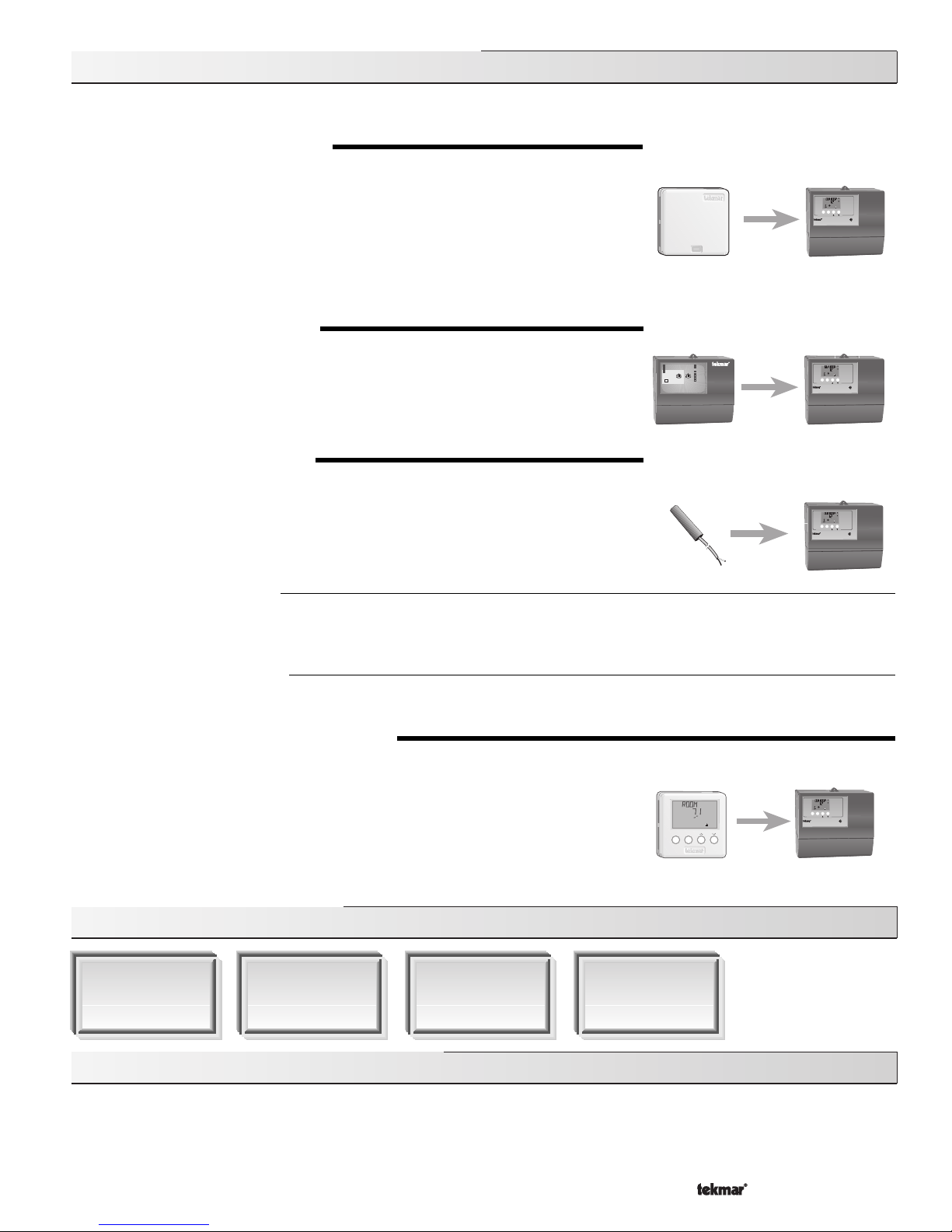
Section C: Snow Melting (Mode —2—)
Section B2: Alternate Mixing Demands (Mode —1—)
In addition to using conventional thermostats to provide a mixing demand as described in Section B1, the 362 can use a number of other
methods to provide a mixing demand.
10K INDOOR SENSOR (10K = INDR)
Set the 10K item to INDR to add an indoor sensor for temperature control of a single zone
mixing system. The indoor sensor is connected to the
Com
and
10K
terminals (14 and 15).
In addition, power must be applied to the
Mix Demand
terminals (1 and 2) as described in
section B1. With the indoor sensor connected, the 362 is able to sense the actual room
temperature. With this information, the 362 provides a more constant water flow through the
mixing system. At the same time, indoor temperature feedback fine tunes the supply water
temperature in the mixing system to prevent over heating or under heating. To adjust the room
temperature for the mixing zone, use the ROOM
Occupied
or
UnOccupied
setting in the Adjust
menu at the control.
10K ZONE CONTROL (10K = ZoIn)
Set the 10K item to ZoIn to add indoor temperature feedback control of multiple mixing zones.
Control of mixing zones is provided by connecting a tekmar zone control to the 362. The zone
control provides its own internal
mixing demand
to the 362. In this case, there is no need to
provide an external
Mix Demand
as described earlier in Section B1. The zone control is
capable of automatically adjusting the MIX TRG temperature to improve building occupant
comfort and system performance.
10K SLAB SENSOR (10K = SLAB)
Set the 10K item to SLAB to add a slab sensor for temperature control of a single zone mixing
system. The 362 can use a slab sensor to control the actual slab temperature. A slab sensor
is placed in the slab and connected to the
Com
and the
10K
terminals (14 and 15). Power must
be applied to the
Mix Demand
terminals (1 and 2) as described in Section B1. With the slab
sensor connected, the 362 will limit the mixing supply temperature in order to maintain the slab
sensor between the SLAB MIN and SLAB MAX settings.
Slab Minimum
(SLAB MIN)
The SLAB MIN sets the minimum allowed core temperature of the slab as long as the control is not in a WWSD. Caution should be
used when adjusting the SLAB MIN setting as this may lead to overheating of the zone during mild conditions. If the AWAY setting
is selected in the Schedule menu, the 362 ignores the SLAB MIN setting.
Slab Maximum
(SLAB MAX)
The SLAB MAX sets the maximum allowed core temperature of the slab. If the slab is to be maintained at a fixed core temperature,
set SLAB MAX and SLAB MIN items to the same setting.
ROOM TEMPERATURE UNIT (RTU) 062, 063
If the mixing system consists of a single zone, temperature control of that zone can be provided
by using an RTU. The RTU is connected to the
Com
and tekmar NetTM
tN1/tN2
terminals
(11 and 13). In addition, power must be applied to the
Mix Demand
terminals (1 and 2) as
described in Section B1. With the RTU connected, the 362 measures the actual room
temperature. With this information, the 362 provides a constant water flow through the mixing
system. At the same time, indoor temperature feedback fine tunes the supply water
temperature in the mixing system to prevent over heating or under heating. The RTU allows
the user to adjust the desired room temperature at the RTU. Remote sensor capability is also
available through an RTU as described in the RTU data brochure.
Section C1: General Snow Melting
The Mixing Control 362 is capable of controlling a single zone snow melting system. In order to provide the best control of the snow
melting system, the 362 should be equipped with an optional tekmar Slab Sensor 072 or 073 and an optional Universal Sensor 071 that
measures the slab return temperature. These can be purchased separately or as part of the Snow Melt Enable Kit 092. The Kit also
includes alternate Start / Stop module 039. With these installed, the 362 is capable of providing the features listed in the following section.
Also described in this section are several different methods of starting and stopping the snow melting system.