Teknoloji Ekibi Delta Pulse 3S Plus User manual

1
User Manuel

2
1- INTRODUCE
On the surface, everything is over, if you say we need
a deep detector, even if you say we need the deepest
detector,also you want to search coins that near the
surface, not enough of them we want to
searchunderground imaging, Delta pulse 3S Plus with
the right product you have received
GROUND BALANCE TECHNOLOGY
Delta Pulse 3S Plus with ground balance technology
offers the solution to the problem of mineral
exactly.You can serach in the structure of any soil.
FOR EACH PERSON 6 WORKİNG MODE
Delta pulse 3s Plus chosen the appropriate structure to use each style has 6 working modes. From this mode
1:Standart Pulse Metal Detector, 2 :İron Off mode, 3:Mineral elimination mode without ground balance, 4:Ground
Mode, 5:Ground mode with manuel , 6:3D İmaging mode. Which of these modes by selecting the appropriate
perfect can be use.
Shortly: Mode 1 : Open the device and search you do not
need any setting.
Mode 2 : Do not detect iron
Mode 3 : Mineral Mode
Mode 4 : Ground Balance Mode
Mode 5 : Manuel Ground Balance Mode
Mode 6 : 3D İmaging System
DISCRIMINATON
Delta pulse 3s Plus at the top of the screen seen during metal
detection ferrous-non ferrous metals with value and can be
used to analyze two categories of articles as worthless. Seen
on the left side of the screen with the numbers can give an
idea about the type of metal.
3
Multifunctional Compact Product
Delta Pulse 3S Plus has 32 cm smal coil,1X1 deep search coil and Gradiometer sensor.You can search coins,deep
search and 3D imaging together.it is multi-functional and is a very useful product. This feature is due to a
combination of, terrain, the ability to use a single device to come out with a few different job offers.
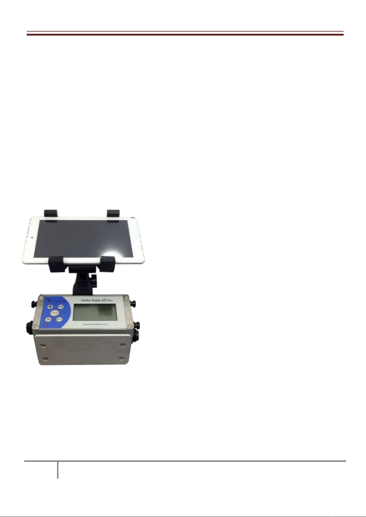
Ergonomic Structure
Mounted on a Delta pulse 3s Plus Tablet, a kite that do not make the clutter of cables with the title of a very
ergonomic design and structure. Delta pulse 3s plus high-quality materials and thoughtful engineering of these
materials is very compatible with that structure. This ergonomic structure is also due to the detector underground
imaging system during use, is easy on the difficulty
ADVANCED TECHNOLOGY VERY EASY TO USE
Delta pulse 3s pulse induction Metal Detector with high detection
capability at a depth Plus technology. The radiometer sensor to a high
structure determination from deep and has the ability that comes
with it. Also the patented One-Touch adjustment feature easy
operation it offers very territorial. Delta pulse 3s plus when it is used
MODE 1 in without needing any adjustment after it is opened in
mode no way can work. Delta pulse 3s Plus with all the data and
settings that have been applied that will appear on the screen in the
form of one screen of each setting can be use with the app menu
without clutter in the way. And only the money calls in both deep
imaging searches in both underground in the process offers very easy
to use.
The use of the detector, the detector can be passed to the direct call
by pressing the tune button open and at a level that is easy. Yes you
read it right. Delta pulse 3sPlus without the requirement of the setting can be used. With it the user himself who
wants can make the settings manually. Also feature patented metal and can perform gap detection to find cavity
at the same time.

4
Examination of the ground with 3D imaging
Product if taken as 3D, both with radiometer detectors you can view live shots from your computer with both.
Radiometer detector is used for metal detection sensor for the determination of the structure. In this way, the soil
structure and to the metal from the computer display can be performed. Delta pulse 3s Plus is obviously not a full
team when taken as requirement no other product.
SIX DIFFERENT OPERATING MODES
Delta pulse 3S Plus 6 different operating modes thanks to the usual from the soil, mineral soil, metal detection and
various detection fields from space appropriate to the way users work station.
USING TECHNOLOGY WITHOUT SETTING
Delta pulse 3S Plus is a product that can be used without the need for setting any land. Mode 1 Open is used only
for use when the detector is sufficient. In no way can be used without adjustment.
Iron switch technology
Delta pulse 3S Plus Mode 2 of detection in use were Iron the iron is capable of cutting off the sound when I
realized that perceptions of qualifying.
Attention! Metals iron as iron as iron which may be perceived perceived or shutdown mode with the closure
brings. In use, it needs to pay attention to.
Ground Balance Technology
Delta pulse 3S plus real actual ground balance mode thanks to the technology of the fourth to make the detector
mono coil bears the distinction of being the first indigenous soil settings. In this way, the minerals can be carried
out without being affected by the easy and efficient way search.
Manual Adjustable Ground Balance Mineral Technology
Delta pulse 3S plus real technology ground balance, as well, where you can manually select the level of fashion has
a very special mineral. In this way, you can do it manually yourself as much as you want mineral qualifier.
Attention! Manual setting of sensitivity may deteriorate due to incorrect settings in the mineral to the metal. He
sat down to watch it during tuning.
5
2- Delta pulse 3S plus parts
Delta pulse 3s plus 15 cm up to 60 cm suitable for use with single from the title can be used. Search deep with
1x1m, title, or 1.5x1.5m kite can be used in the title.
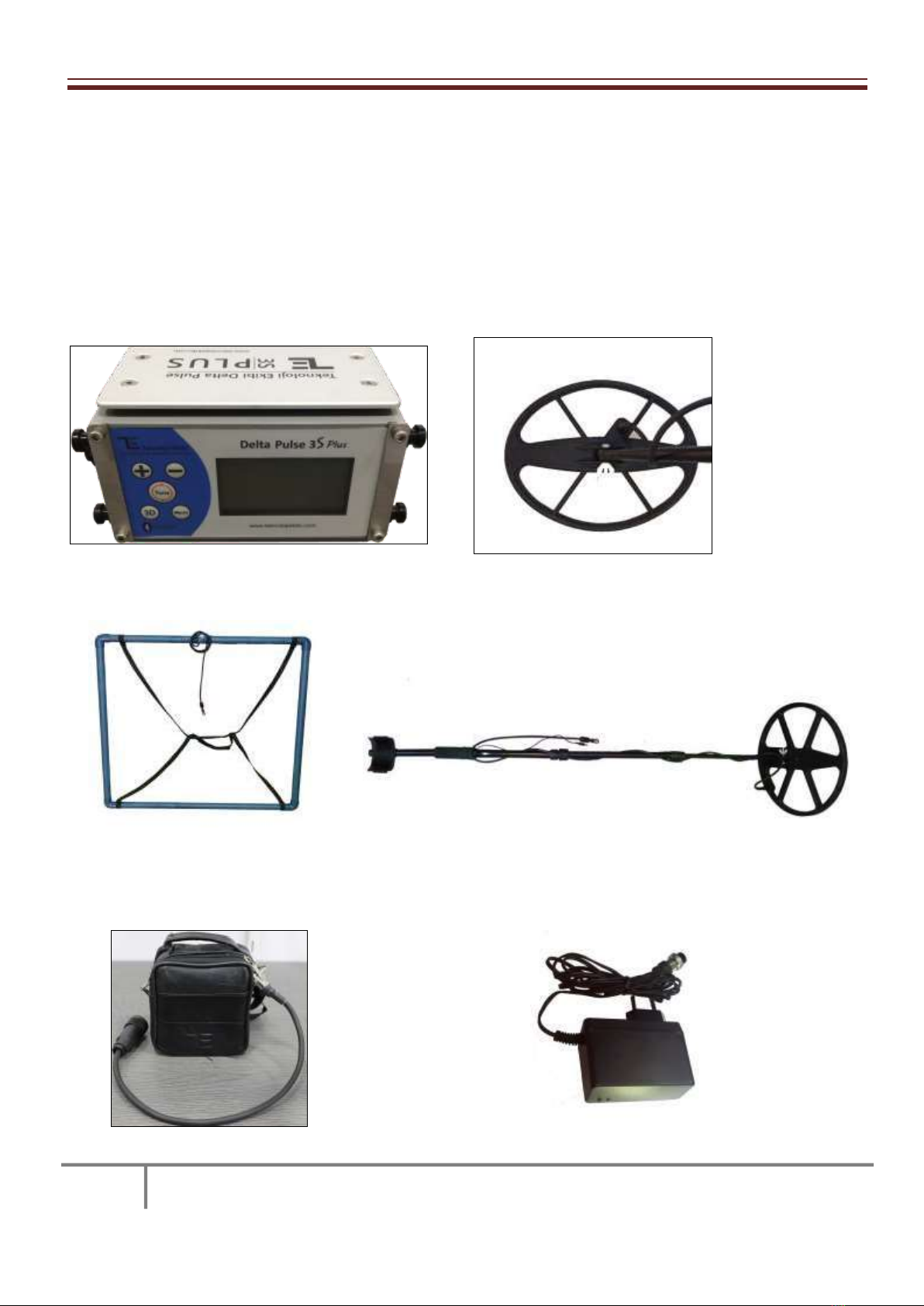
Detector Delta pulse 3S Plus, you will receive the included parts:
1- Main Unit 2- Small Coil
3- 1X1 Coil 4- Handle
5- Battery and cable 6- Charger
6
8- Gradiometer
9- Tablet PC
Figure 1

7
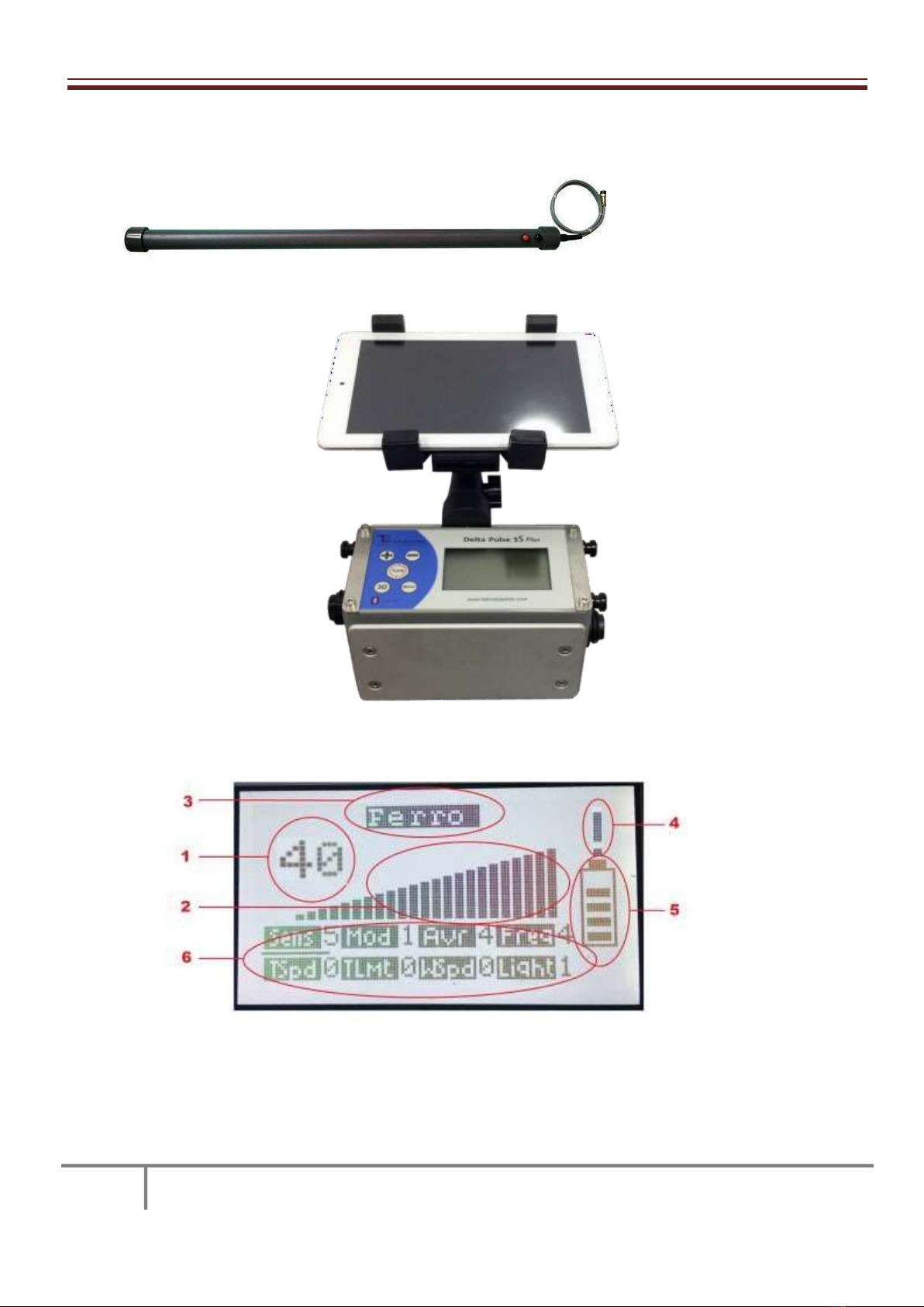
3–The meaning of the buttons and icons on the screen of
the detector
1- metal with Part numbers this is to enable a distinction to be made. The precious metal are likely to be higher
than the figures contained in this section. There is no way to represent each figure of another metal. In general,
the value of the figures if it is below 30, the metal iron and its derivatives, staying on if it is non-ferrous in the form
of can be classified.
2- This section refers to the perceived strength of the metal. Depending on the power of perception contained in
this section bars the increase.
3- a magnet for the separation of metal that holds or does not hold for this part. Holding the magnet FERRO
metals, NONFERRO metals in the magnets and it does not hold writes. After a certain period of time from the
instant of detection of this paper, i.e., the detection of the metal seems to be when you get to a certain level.
Consider the distinction in logic of the detector in the form of allocate valuable working area. Instantly detection
the distinction on the distinction therefore should not be expected.
Attention! The discrimination capability of the detector of 60% -70 order. 100 %accurate should not be expected
to perform metal separation.
Attention! So the class holding the magnet Ferro metals Iron NONFERROUS aluminum derivatives and the part
that says " includes gold, copper, tin, lead, etc. includes metals.
4- the soil of this section relates to the setting of the detector. The setting of your soil in good condition are seen
as the exclamation mark in this section if it is not continuous. In this case, the detector setting of the soil must be
made. I don't get out while the case to be considered is the necessity to detect this metal sign. Detects metal while
the point does not bear the meaning demanding setting.
Attention! The fields off the metal detector, high voltage near the base station, near industrial zones and relatives,
near areas such as radio relays if you run the product due to electrical noise, it constantly tells you that you can
make it work by removing the mark, and the soil does not hold the setting.
5- This shows the status of the battery charging section. Depending on the occupancy rate of the battery, fill the
inside of the shape.
Attention! The detector is first turned on and the battery indicator will show empty when the setting is made of
soil that will come to the level of measurement and should be again. This is a symptom that is related to a problem
with the battery or the battery is low.
6- settings of the detector is made in this section. Figure 1 also sens adjustment made in line with the part to be
found under the section are selected. This button is used to process the menu selection. When it comes to the
part to be adjusted with the MENU button The –and + buttons to change the parameter is provided.

8
We would like this part in order to explain what is the use of:
Sens: adjust the sensitivity of the detector is the part that is used to. The sensitivity of the parameter value will be
so high. With the rise of precision that should be considered is the possibility that interference can bring.
Attention! High sensitivity also increases the probability of detection of mineral. Therefore, the detector sensitivity
should be determined by the condition of the land where the structure will be used. If you believe that you cannot
determine this, if you leave this value at 5.
Mod: the part where the detector operating mode is selected. The detector has 6 different working modes. The
mode of operation with the following sequence can be used for the purpose of writes.
1–This mode of operation for general use. Mineral soils with sandy coastal area and less mineralized normal
water use for the appropriate operating mode. The highest detection range in this mode can be obtained.
2- This mode of operation is the mode that is used to distinguish the voice. Fashion metal detection in the
detector in addition to worthless with the sound of the first cut.
Attention! In this mode the sound is cut in said detector unworthy of all perception. One important point that
needs to be known what kinds of metals the detector is worthless, he said.
3- Operating Mode This mode of operation is suitable for use in areas of high mineral and stony. In this mode, the
mineral is considered by the detector to the level of a given level and this level is set. This mod should not be used
on mineral soils.
4- This mode of operation very high mineral fields, and fields of broken brick in the pit to use the appropriate
operating mode. In this mode, the detector does not set the level of the mineral itself. The mineral level of the soil
according to the setting that you will do sets. Tune for it is performed. During this process the coil 50cm or more
from the ground up arrow while in the air is observed should be kept. Shows a DOWN ARROW, while the position
or job of the search coil should be placed under than 1-2 cm. When the setting is completed, the status signaling
into the ground if the setting should be repeated.
Attention! In this mode of operation the detector mode 1 according to the fashion of the distance is experiencing
a loss.
5- This mode of operation very high mineral fields, and fields of broken brick in the pit to use the appropriate
operating mode. In this mode, the detector does not set the level of the mineral itself. The mineral level of the soil
according to the setting that you will do sets. During this process the coil 50cm or more from the ground up arrow
while in the air is observed should be kept. Shows a DOWN ARROW, while the position or job of the search coil
should be placed under than 1-2 cm. If you have a situation like on the ground signaling with the + button should
be increased if the level of the mineral in the ground if you have a situation like cutting the sound –level of the
mineral with the button should be reduced. This process removed up and back down the coil to each increase or
decrease should be lowered. When the setting is completed, return to the main display by pressing the tune
button.
Attention! In this mode of operation is due to the distance to the detector in iron and iron derivatives.

9
6- finding mode this mode of operation the patented tried-and-space at the same time, underground imaging
modes. When this mode is selected on the screen after the setting is made of the soil in a straight line is observed.
The shapes of metal detection on this line upwards, downward shapes how we perceive space. This mode to the
ground during use of the coil in case of a change in the distance can lead to erroneous information.
Attention! This product is basically a metal detector. Finder space. In space mode in use, detection distance,
detection distance is lower than are realized as metal. Space is a feature of the discovery process it should be
noted that the secondary detector. Since the basic operation of the detector metal detection, metal detection
performance will be the difference between gap detection performance.
AVR: detection of the detector that you will use for the calculation of the filter coefficient that determines the
part. The parameter used here is also increasing in direct proportion to the level of filtering. Filtering the electrical
noise reduces the sensitivity of the detector to high. However, the speed and accuracy of detection reduces. High
AVR sensitivity value should not be set necessarily to live and work in situations that should be taken into account
a slowdown in losses. The value should not be increased and therefore unnecessary AVR should be kept as low as
possible.
FRK: you set the ground tone volume of the detector, if desired the part where Semin muted state. The sound
must be set to 0 if the ground is required.
TSpd: the land of the detector that will be set with the automatic setting, adjust the speed to be set is the part
where what happens to the soil. In this section, The parameter is set to 0 when the soil is done automatically in
the setting of the detector. Any number except 0 when the parameter is set, the detector automatically begins
adjusting to the changes of the soil. This setting is made according to the speed parameter value takes place. The
speed setting is directly proportional to the value of the parameter. Value grows as the speed of adjustment is
increasing.
Attention! The recommended setting for this section is high in mineral soils, mineral soils of the low values in the
selection. If the value for this setting and leave at 5 If you understand the logic.
Tlmt: the land of the automatic setting of the detector is the part which determines what will be done to detect
level. In this section, The number to be selected as one grows higher detection will automatically reset. Figure 9 in
this section if you selected as the automatic setting as the infinite limit of soil is determined.
Attention! The recommended setting for this section is high in mineral soils, mineral soils of the low values in the
selection. If you understand the logic, please leave at 9 If the value for this setting.
Attention! Automatic soil setting within the limit specified in the selected detector for inability to comply with
Section tkmt will make all the perception. How is this being complied with in a time of tspd in part by the selection
of the speed will be determined. In the light of this information if the user waits motionless on a metal metal
detector can perform the attunements, and normal soil are passed onto an automatic adjustment in the back
ground until you make unless may perform metal detection.

10
4 –Preparation For Use Of The Detector
Detector equipment should be made ready for combined use. For this the following steps should be followed.
1- as shown in Picture 2 and picture 3 should be first made ready for use to be used as a coil. The coil the larger
coil to be used in the form of a square with the pipes to each other should be reviewed and should be
compressed. The small coil with the coil to be used must be installed on the coil holding arm, the retention arm
and the cable should be wrapped.
2- The battery of the user as shown in Figure 4 and the left arm to hang by the neck.
3- user detector as shown in Figure 4 should not exceed the main unit around your neck.
4 - small coils to be used, as shown in Figure 4, large bobbin
if 2 is to be used. a person with the help of the coil should be kept.
Attention! The metal detector near the area and high voltage environment
should not be employed.
5 - the detector Coil connector and the battery connector as shown in Figure 4
must be installed. This process is being performed while the battery first, then the coil must be installed. After this
process, the detector has become ready for use.
Figure 2 Figure 3 Figure 4

11
5–The Use Of The Detector
5.1 - searches with the small coil.
In a search to be made with a small coil that the detector is ready to use the tune button must be held pressed to
open. Delta pulse 3s Plus Tune button on the screen with the look of the logo should be left. During this time, the
detector's search coil must be kept in position. After the logo appear on the screen in the opening post will be
seen. The next sequence of this paper is to be seen at the 5 spot, and then the loading post will be seen.
Loading of the script under 1% than the 99% of loading a program to count information will appear. Upon
completion of the installation of the program the main screen of the detector will appear. The main screen
appears with the detector the detector is ready for use. If the detector 4. or 5. if the mode is to be used in the
detector must be made in the setting of this mode is taken into the soil. The adjustment of soil is a process that is
performed in two steps.This is the first step, Tunning, and the second Zero stop.
Ground Balance For Mode 4 :
Tunning coil 50cm from the ground when held in the air to make the tune button on the detector must be held
pressed. The tune button is held down on the screen while the tuning post will be deleted and all posts will be
seen in a window. Meanwhile, at the same time, indicating that up to the top of the coil should be kept above the
arrow mark will appear. Tunning during the process, the position of the detector coil should not be changed.
Tunning down the UP ARROW will give the direction when the process is complete. When the down arrow
appears, the detector's search coil to the position should be lowered. A short drive down the coil after it has been
downloaded, the arrow mark will be deleted and the ratio of mineral soil at the bottom of the frame where it says
Tunning it will be seen. After this process, the setting will be completed and you will come to the main screen of
the soil. When the main screen comes up, if necessary, Zero the process can also be done.
Ground Balance For Mode 5 :
Tunning coil 50cm from the ground when held in the air to make the tune button on the detector must be held
pressed. The tune button is held down on the screen while the tuning post will be deleted and all posts will be
seen in a window. Meanwhile, at the same time, indicating that up to the top of the coil should be kept above the
arrow mark will appear. Tunning during the process, the position of the detector coil should not be changed.
Tunning down the UP ARROW will give the direction when the process is complete. When the down arrow
appears, the detector's search coil to the position should be lowered. If the search coil is lowered to the position
of the coil back into the air when the buzzer sounds if the detector should be lifted and with the + button of the
mineral by increasing the level of the coil should be lowered back down. If the search coil is lowered to the
position of the detector when the coil is lifted into the air again cutting in and should be audio - button with the
coil by reducing the level of the mineral should be lowered back down. The voice coil up and down when it is
lowered when it is removed, this process must continue until a change in. The soil tuen when the setting is
completed by pressing the button again donulebilini the main working screen. When the main screen comes up, if
necessary, Zero the process can also be done.
Attention! In order to obtain high efficiency it is advised to use with the sound detector of the ground.

12
The soil remained to be made after the setting is completed settings to the user's request. The setting of the soil
after it is done, is seen as an exclamation mark on the battery indicator if the setting has been done on soil as it
should. In this case, the setting must be made again of the soil. In addition, setting of the soil after a while, the
battery indicator on the exclamation mark still appears, it should be understood that the setting should be
performed again soil. The most important elements to be considered during use 4. and 5. search for the mod
positions, except for the coil remain constant, and search speed that is appropriate to the operating mode
selected. 4. and 5. the detection of changes in the earth with the distance between modes except the coil can
impair the quality of. 4. and 5. the coil may constitute a drawback in the change in the distance modes in any
place. The passing rate on the ground of what is the mode of the coil used is of major importance.
Attention! It was opened the setting of the detector was made of the soil in the area in case you have this metal
detector detects metal, and the opening operation cannot complete.
5.2 - searches with the large coil
The large coil (Frame, title, or the title kite)is the first issue to be aware of calls to be made if the frame header is
to be used 2. help should be taken from a person. Frame titles are not intended for single person use. Single
person use Great titles that are suitable for the kite-type headers.
A large coil with the coil sets to be made small with the settings in the same. For this reason, the written
information can be taken into account for the small coil.
The most important elements to be considered during use 4. and 5. in all modes except mode, the search coil
should remain constant with the position of a square in the case of two users to each other due to the
synchronous motion. 4. and 5. the detection of changes in the earth with the distance between modes except the
coil can impair the quality of. This case 4. and 5. in the modes.
Attention! Users should be careful not to headings on large metal or with a telephone.
6. Usage Details
Things to be considered before opening
-To be full of battery charge should be considered.
-Metal should not be in your location.
-House should be careful not to be, such as in indoor environments.
-High voltage lines should not be close to.
-Large coil(Square or kite) will be used if not any metal on you
it should be noted.
-Physical detector coil and careful not to damage your cables must be.

13
Use should be considered during
-Slow in the manner it should be moved during use of the detector coil.
-The detector will automatically tune when it is set in a manner that should not be waiting on the metal too.
-To-earth setting is made 4. and 5. setting mode other modes it should be noted that in a different way than the
soil.
-User mode 3. 4. and 5. mineral modes is used to eliminate Iron, because that will decrease sensitivity to take into
consideration. Cube and brick, broken in pieces, the detection occurs in this material, the reset needs to be done
and should not be ignored.
-All modes of movement to be parallel to the ground in a coil and the coil should be considered. The detection of
changes in the distance to the location of the coil may cause a deterioration in performance.
-6. place the coil in the detector space, so use the mod mode according to the change in the distance in normal
mode is more effective.
Attention! This product is a metal detector. The discovery the discovery feature space is lower than of metal. From
a distance of the detector from the metal finds should not be expected to have space.
-Metal separation in the response of the detector in a very nearby metal objects errors can occur. The detection
made at points very very powerful distinction therefore should not be trusted. Detection if the metal is very strong
to the point that the distinction be made by boarded down from the top of the coil is recommended.
The use of 3D
2 The use of 3D in the classroom should be evaluated. These 3D shots and 3D shots made with made with the
Radiometer detector.
The following steps should be applied in what order the shots with the detector.
1. The detector must be made ready for use.
2. Tablet must be opened and then TE 3D Viewer program must be opened on the tablet.
3. Mod of the detector must be chosen 6.mod .
4. Bluetooth connection icon must be chosen on TE 3D Viewer program and bluetooth connection must be
provided.
14
Figure 5
5.TE icons with the help of 3D viewer program as shown in Figure 6 to be made to the display settings window
should open.
Figure 6
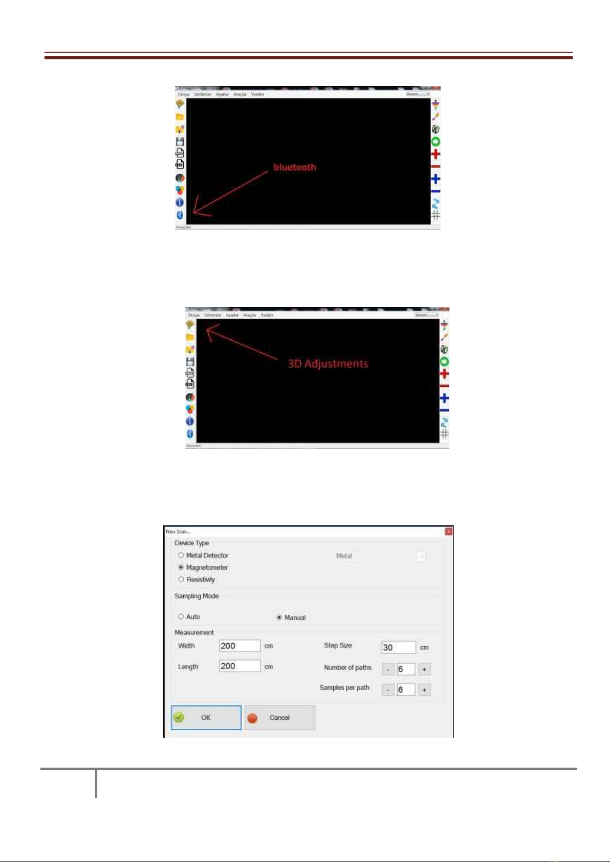
6. The part with the metal detector part Figure 7 in the window that opens should be selected.
Figure 7
15
7. The capture will be performed in the same window the length and width of the field where information must be
entered.
8. Must be entered step size at the same window. Program will calculate sample periods and sample ways with
using size of the area and step size. Step size is choosible due to user need. But our advice is use same dimensions
with coil size.
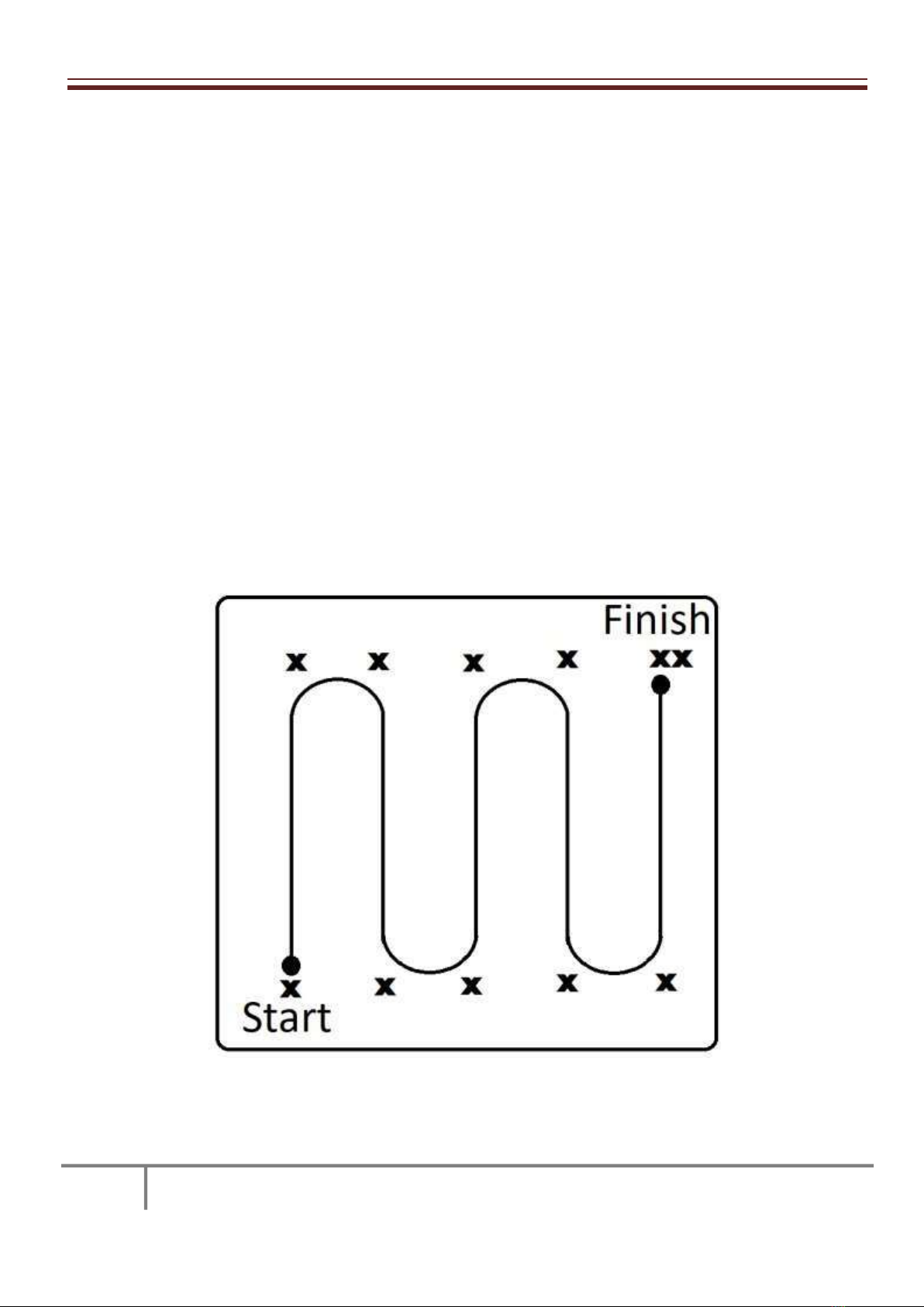
9. The above settings are done, it should be located at the lower left side of the display area. In the process of the
shooting area of the imaging start shooting left six, finishing the shot on the right is the shadow. How to do the
sampling during shooting are shown in Figure 8. When switched to the lower left corner of the shooting settings
on the screen shot select the OK button. An image comes on the screen as shown in Figure 9 The result of this. The
region circled in red here your shots during a match the nth sample path and in that path that were in the shows.
The Cancel button also at the end of the path next to the road under the direction of the Direction Change! In the
form of a warning the next part is located. Point to note here is that the sample was taken and how many how
many ways change the way and be known! The other way to pass an alert must be known. When these guidelines
are followed tread a path as shown in Figure 8. The 3D button on the main unit button during shooting will be
used as the sampling detector. During shooting, when each button is pressed, the image on the tablet screen from
the current position to the corresponding location in the received data by adding the attraction takes place in a
concurrent manner. The final version of the image on the screen will appear when shooting is complete.
Figure 8

16
Figure 9
The following steps are what should be applied in the order in shots with a gradiometer.
Gradiometer with three very important points to be considered before we start shooting during shooting. The first
of these is the direction of the sensor. Sensor and should not be changed in any way during the shooting of gone
this direction should be North or South. Second, angle and ground distance of the sensor. This angle musn’t be
changed in any way, and should look as upright as possible in the place. The changes that will occur at the position
sensor is caused to display incorrectly. The sample is seen in Figure 10 the shape of the grip sensor.
Figure 10
1. The sensor and the battery must be installed in the detector, but the detector should not be opened.The supply
voltage required for the operation from the synchronous detector. For 3D viewing does not require you to operate
your detector. If you want to turn on the detector while the sensor is plugged in will not work.
2. Tablet must be opened and then TE 3D Viewer program must be opened on the tablet.

3. Bluetooth connection icon must be chosen on TE 3D Viewer program and bluetooth connection must be
provided.
Figure 11
4.Icon to seen in Figure 12 with the help of 3D viewer program to be made to the display settings window should
open.
Figure 12
5. Gradiometer Figure 13 the part with the part in the window that opens should be selected.
17

18
Figure 13
7. The capture will be performed in the same window the length and width of the field where information must be
entered.
8. Must be entered step size at the same window. Program will calculate sample periods and sample ways with
using size of the area and step size. Step size is choosible due to user need.
9. The above settings are done, it should be located at the lower left side of the display area. In the process of the
shooting area of the imaging start shooting left six, finishing the shot on the right is the shadow. How to do the
sampling during shooting are shown in Figure 8. When switched to the lower left corner of the shooting settings
on the screen shot select the OK button. An image comes on the screen as shown in Figure 9 The result of this. The
region circled in red here your shots during a match the nth sample path and in that path that were in the shows.
The Cancel button also at the end of the path next to the road under the direction of the Direction Change! In the
form of a warning the next part is located. Point to note here is that the sample was taken and how many how
many ways change the way and be known! The other way to pass an alert must be known. When these guidelines
are followed tread a path as shown in Figure 8. The 3D button on the main unit button during shooting will be
used as the sampling detector. During shooting, when each button is pressed, the image on the tablet screen from
the current position to the corresponding location in the received data by adding the attraction takes place in a
concurrent manner. The final version of the image on the screen will appear when shooting is complete.
Attention! The diameter of the coil have to be erased and rewritten even though the tab is correct.
Attention! The sensor of the radiometer is determined by looking at the directional buttons. The buttons look in
the direction of North or South when the north began shooting and during shooting always if you look at the
north, when the South began shooting during shooting, if you look at always should be positioned facing south.
Attention! Shooting to be done with the sensor in position and the position of the radiometer is of great
importance. This location and position the location and position should be kept as far as possible during reset.
Attention! He wants the user that will use filtering to get the image shooting section. Therefore there is a value
that should be. The user should choose the values to be selected depending on their request.
The Meanings Of The Filter
1- December filter: this filter works only for this range and selecting the range of the desired signal to be
displayed.
2- in depth filter: this filter works to strengthen the signal within the desired range of the desired rate.
3- filter surface: on the surface of the metal resulting from the abolition of benefit from a very high perception.
4 - Separation filter: with only perceived as valuable to be displayed on the screen of metal detection works.

19
8–The Program's Main Screen
The icons in the main screen of the program shown in Figure 8.
9–Data Interpretation
To interpret the data, the first image on the screen are the logic of how should know. The largest one of the
received data to the right of the color Valence color scale is assigned. This original is red in color. The far left of the
least significant of the received data to one color scale color is assigned. This color is blue. Perceptions Dec the
remaining colors are distributed. As can be understood from this situation, a color, an object, or the value of the
metal is given. So, did you see the Red metal or red you may have seen a grave like it's nothing. Shot on the
received image, the perception, perception and perceived value for the power of the scale makes a comment that
is evaluated at the same time.
For example:
Mineral Metal Detector 1 and valence perceptions is regarded as smaller. The detection point is regarded as a
small metal. The figure that is perceived as the shape of the metal or are struggling to grasp.
The radiometer anomaly positive for brick, Khorasan, Iron, Steel, bronze, and soft soil anomaly is considered
negative when the general structure, marble or water is considered to be. Radiometer soil layer 4 and also in
perceptions of value perceptions between 4-12 or sensor move while considered under the mineralized structure
is considered as a metal 12 on perceptions. The power of perception by looking at the detection point, such as
fracture detection, small metal detection, while if a figure or cube can be evaluated depending on the strength of
ihfa, tombs, tunnels, rooms, etc. can be interpreted as such. Below are a few examples of sensing area.
The process is a condition that requires advanced interpretation experience.
Gradiometer Tomb

20
Gradiometer opened and closed ares
Metal Detector Small Metal
Gradiometre iron
Table of contents


