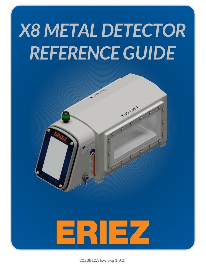
Thermo Scientific Ramsey Oretronic IV User manual

Thermo Fisher Scientific™
Ramsey™Oretronic IV Tramp Metal Detector
User Manual
Thermo Scientific Ramsey Oretronic IV Tramp Metal Detector

Ramsey Oretronic IV Tramp Metal Detector REC 4479C Page 2
REC4479 Rev C
Part number 190017—English
This document is confidential and is the property of Thermo Fisher Scientific. It may not be copied or
reproduced in any way without the express written consent of Thermo Fisher Scientific. This document also is
an unpublished work of Thermo Fisher Scientific. Thermo Fisher Scientific intends to keep, and is maintaining
the work as confidential information. Thermo Fisher Scientific also may seek to protect this work as an
unpublished copyright. In the event of either inadvertent or deliberate publication, Thermo Fisher Scientific
intends to enforce its rights to this work under the copyright laws as a published work. Those having access to
this work may not copy, use, or disclose the information in this work unless expressly authorized by Thermo
Fisher Scientific.
Microsoft and Windows are either registered trademarks or trademarks of Microsoft Corporation in the United
States and/or other countries.
All other trademarks are the property of Thermo Fisher Scientific and its subsidiaries.
© 2016 Thermo Fisher Scientific, Inc. All rights reserved.

Ramsey Oretronic IV Tramp Metal Detector REC 4479C Page 3
Table of Contents
Table of Contents ...............................................................................................3
About this Manual ......................................................................................... 9
Important Safety Information........................................................................ 9
The Difference between a Caution and Warning Message............................. 9
General Safety Precautions............................................................................ 9
Conventions Used in This Manual................................................................ 10
Introduction .....................................................................................................11
Overview...................................................................................................... 11
Theory of Operation .................................................................................... 11
System Components.................................................................................... 13
Support Structure & Coils ............................................................................ 14
Control Unit ................................................................................................. 15
Features and Options................................................................................... 16
Simplified Operator Interface ...................................................................... 16
Increased Detection Sensitivity.................................................................... 16
Field Upgradeable Software......................................................................... 16
Modbus Interface ........................................................................................ 16
Synchronization of Transmitter Pulses......................................................... 16
Speed Sensor ............................................................................................... 17
Clip Detector................................................................................................ 17
High Pile Detector........................................................................................ 17
Time Delay Marker ...................................................................................... 17
System Requirements.................................................................................. 17
Technical Specifications ............................................................................... 18
Installing the TMD IV ........................................................................................19

Ramsey Oretronic IV Tramp Metal Detector REC 4479C Page 4
Overview...................................................................................................... 19
Installation Considerations .......................................................................... 19
Mounting Location....................................................................................... 19
Electrical Specifications................................................................................ 20
Customer Supplied Fusing Requirements .................................................... 20
Output Relay Rating..................................................................................... 20
Safety Precautions ....................................................................................... 20
Equipment Handling .................................................................................... 21
Inspection and Unpacking............................................................................ 21
Storage ........................................................................................................ 21
Installing the TMD IV.................................................................................... 21
Installing Coil Support Structure & Coils for Dual Coil TMD IV...................... 22
Installing Coil Support Structure & Coils for Under Belt Single Coil TMD IV.. 22
Installing System Devices............................................................................. 23
Mounting the Control Unit........................................................................... 23
Field Wiring the TMD IV............................................................................... 26
Critical Wiring Conditions ............................................................................ 26
Field Wiring Procedure ................................................................................ 26
Procedure to Wire the Control Unit............................................................. 27
Connecting Incoming Power ........................................................................ 28
Heater Power and Thermostat Setting......................................................... 28
Initial Power On ........................................................................................... 28
Setting System Options................................................................................ 29
Measuring Belt Speed.................................................................................. 29
Calibrating the Speed Sensor ....................................................................... 30
Calibrating Sensitivity .................................................................................. 31
Calibrating Clip Sensitivity............................................................................ 32
External Communication.............................................................................. 33

Ramsey Oretronic IV Tramp Metal Detector REC 4479C Page 5
Operating the TMD IV.......................................................................................34
Overview...................................................................................................... 34
Operator Interface....................................................................................... 35
Front Panel LEDs.......................................................................................... 36
Keypad......................................................................................................... 36
Options Screen............................................................................................. 37
Sync Input.................................................................................................... 38
Bar/Rod Detect............................................................................................ 38
Clip Detect ................................................................................................... 38
Speed Sensor ............................................................................................... 38
External Comms........................................................................................... 38
Language ..................................................................................................... 38
Units ............................................................................................................ 38
Line Frequency............................................................................................. 38
Password Protection.................................................................................... 39
Settings Menu.............................................................................................. 39
Belt Speed.................................................................................................... 40
Material Code.............................................................................................. 40
Operating Frequency ................................................................................... 40
Reverse Direction......................................................................................... 40
Marker Distance .......................................................................................... 40
Marker Duration.......................................................................................... 41
Clip Length................................................................................................... 41
Bar Length.................................................................................................... 41
Modbus Address.......................................................................................... 41
Modbus Port................................................................................................ 41
Modbus Baud Rate ...................................................................................... 41
Persistent Bypass......................................................................................... 41

Ramsey Oretronic IV Tramp Metal Detector REC 4479C Page 6
View Menu .................................................................................................. 41
Normal Operation........................................................................................ 42
Maintenance and Troubleshooting...................................................................43
Overview...................................................................................................... 43
Routine Maintenance .................................................................................. 43
Troubleshooting........................................................................................... 43
Visual Inspection.......................................................................................... 44
Diagnosing and Correcting Problems ........................................................... 44
False Tripping............................................................................................... 45
Correct the Coil Imbalance........................................................................... 45
Finding the Source of Mechanical or Electrical Noise................................... 47
Adjusting for High Product Noise (Mineral Ores) ......................................... 49
Adjusting for Clip (Belt Splice) Detection ..................................................... 50
Passing Tramp Undetected .......................................................................... 51
Changing Material Code to Adjust Sensitivity .............................................. 52
Testing for Coil or Junction Box Damage...................................................... 52
Testing the Transmitter Coil......................................................................... 53
Testing the Receiver Coil.............................................................................. 53
Installing Default Values .............................................................................. 54
TMD IV Modbus Interface............................................................................ 54
Overview of TMD IV Communications ......................................................... 54
Modbus Message Types Supported by TMD IV............................................ 54
TMD IV Holding Registers............................................................................. 55
Register Details ....................................................................................................................56
Service Codes ............................................................................................................................................ 56
Service Result ............................................................................................................................................ 57
Material Code............................................................................................................................................ 57
Coarse Sensitivity ...................................................................................................................................... 57
Operating Frequency................................................................................................................................. 58

Ramsey Oretronic IV Tramp Metal Detector REC 4479C Page 7
Power Line Frequency............................................................................................................................... 58
Language ................................................................................................................................................... 58
Units .......................................................................................................................................................... 59
Normal Fine Sensitivity.............................................................................................................................. 59
Marker Distance........................................................................................................................................ 59
Marker Duration........................................................................................................................................ 59
Nominal Belt Speed................................................................................................................................... 60
Coast Count............................................................................................................................................... 60
Lifetime Trip Count.................................................................................................................................... 60
Speed Sensor Input Enabled ..................................................................................................................... 60
Meters Per Speed Pulse ............................................................................................................................ 61
Actual Belt Speed ...................................................................................................................................... 61
Clip Fine Sensitivity.................................................................................................................................... 61
Clip Length................................................................................................................................................. 61
Clip Coarse Sensitivity Delta...................................................................................................................... 61
Clip Coarse Sensitivity ............................................................................................................................... 62
Alarm Status Bit String .............................................................................................................................. 62
Belt Direction Reversed............................................................................................................................. 62
Clip Detection Enabled.............................................................................................................................. 63
Bar Rod Detection Enabled ....................................................................................................................... 63
Bar Rod Length.......................................................................................................................................... 63
Bar Rod Sensitivity..................................................................................................................................... 63
Modbus Address ....................................................................................................................................... 64
Modbus Baud Rate.................................................................................................................................... 64
Modbus Parity........................................................................................................................................... 64
Modbus Num Stop Bits ............................................................................................................................. 65
Sync Input Enabled.................................................................................................................................... 65
Welding Noise Filter Enabled.................................................................................................................... 65
Service, Repair & Replacement Parts ................................................................66
Service and Repair Information.................................................................... 66
Parts Ordering Information.......................................................................... 66
Parts Lists..................................................................................................... 67
Disposal of Hazardous Waste....................................................................... 67

Ramsey Oretronic IV Tramp Metal Detector REC 4479C Page 9
About this Manual
This manual provides the information you need to install, operate, and maintain the TMD IV.
Read this manual before working with the system. For personal and system safety, and for the best product
performance, make sure you thoroughly understand the manual before installing, operating, or maintaining
this machine.
Important Safety Information
Please note the following important safety information about installing, operating, handling, transporting,
maintaining, and disposing of the TMD IV. The following symbols are used on the TMD IV itself and in this
manual, and convey the following important safety information.
CAUTION. Risk of electric shock.
All warnings and cautionary text in this manual is marked with this symbol. Please read all cautions
and warnings very carefully and fully obey them.
The Difference between a Caution and Warning Message
Two types of safety message are used in this manual, and the distinction between the two is as follows.
CAUTION. Failure to observe may cause minor injury or damage to the equipment.
WARNING. Failure to observe could result in death or serious injury.
General Safety Precautions
Here are the safety precautions you should follow when installing, operating, or maintaining the TMD IV.
CAUTION: The protection provided by the safety elements of this system may be impaired if the
equipment is used in a manner other than specified in this manual.
WARNING. User must follow all applicable safety procedures related to this product. High voltages
and high temperatures are present within the system enclosure during normal operation.
WARNING. Do not attempt to defeat safety interlocks provided with this product. There are no
user-serviceable parts inside the system enclosure. This product must be serviced only by authorized
Thermo Fisher Scientific service personnel.
WARNING. Failure to follow safe installation and servicing procedures could result in death or
serious injury.
•Make sure only qualified personnel perform installation and maintenance procedures in
accordance with the instructions in this manual.

Ramsey Oretronic IV Tramp Metal Detector REC 4479C Page 10
•Allow only qualified electricians to open and work in the electronics cabinet, power-supply
cabinet, control cabinet, or switch boxes.
•Covers over the electronics and rotating parts must always remain in place during normal
operation. Remove only for maintenance, with the machine’s power OFF. Replace all covers
before resuming operation.
•During maintenance, a safety tag (not supplied by the factory) must be displayed in the ON/OFF
switch areas instructing others not to operate the unit (ANSI:B157.1).
WARNING. High voltage that may be present on leads could cause electrical shock.
•All switches must be OFF when checking input AC electrical connections, removing or inserting
printed circuit boards, or attaching voltmeters to the system.
•Use extreme caution when testing in, on, or around the electronics cabinet, PC boards, or
modules. There are voltages in excess of 115–230 V in these areas—even with the main door
open.
WARNING. Use only the procedures and new parts specifically referenced in this manual to ensure
specification performance and certification compliance. Unauthorized procedures or parts can
render the instrument dangerous to life, limb, or property.
WARNING. The TMD IV should not be operated at more than the production rate stated on your
equipment specification sheet, or used in applications other than those stated in the original order.
WARNING. Do not place or store objects of any kind on the TMD IV.
WARNING. Tampering with and/or removing any safety guards and other safety devices fitted to
the TMD IV is strictly forbidden. If the existing guards or safety devices are modified, you must verify
that any changes made comply with the appropriate safety regulations before the TMD IV is used.
Conventions Used in This Manual
Here is a summary of the conventions used in this manual.
•The term “TMD IV” is a general term that refers to Thermo Scientific Ramsey Oretronic IV Tramp Metal
Detector.

Ramsey Oretronic IV Tramp Metal Detector REC 4479C Page 11
Introduction
This section introduces the Thermo Scientific™ Ramsey™ Oretronic IV Tramp Metal Detector (TMD IV). It gives
an overview of the device’s capabilities, provides information on installing, operating and maintaining the
device, along with technical specifications and reference drawings.
Overview
The TMD IV detects the presence of tramp metal in bulk material being transported on a conveyor belt.
Detected tramp metal can then be removed from the process stream manually or automatically by mechanical
means. Removing the tramp metal protects crushers, material handlers, and process equipment from the
damage it may cause.
This highly reliable system detects all types of tramp metal that could be found in bulk material on belt
conveyors even when it is buried in wet, conductive materials. Tramp metal could include such things as
bucket teeth, manganese steel mantles, bore crowns, bar scrap, chains, and tools. The bulk material (or
burden) can be product such as iron pellets, minerals, aggregates, coal, or coke.
The TMD IV can be installed on conveyors with speeds up to 1,800 ft/min (9 m/s). In addition, because it is
insensitive to materials with high magnetic permeability and electrical conductivity, this detector can be used
in applications where conventional metal detectors produce an unacceptable false alarm rate.
The TMD IV control unit includes software that helps ease system setup and calibration. The operator interface
provides easy-to-read indicators, and a membrane-switch keypad.
Theory of Operation
The TMD IV operates by generating a pulsed magnetic field (the primary magnetic field) that is radiated from
its transmitter coil. This field generates an output signal in the receiver coil (see Figure 1-1).
Figure 1-1. Magnetic Fields Generated by the TMD IV
When the pulse is turned off, eddy currents induced in tramp metal produce a secondary magnetic field. This
new field also generates an output signal in the receiver coil. The detector measures the effect of this
secondary magnetic field only during the time the primary field is inoperative.

Ramsey Oretronic IV Tramp Metal Detector REC 4479C Page 12
The material on the conveyor belt also produces a secondary magnetic field. The two magnetic fields can be
distinguished from each other by observing their decay times. The better the conductivity characteristics of
the material, the longer the decay time. As the magnetic field decays, the output signal strength decreases
(see Figure 1-2).
Figure 1-2 How Conductivity Effects Decay Time
Coal, aggregate, and mineral ores have conductivity characteristics considerably poorer than tramp metal,
which means their magnetic field decays more quickly (see Figure 1-3).
Figure 1-3 Ore/Tramp Metal Decay Time Comparison
The TMD IV is designed to take advantage of the difference in decay time by activating its measurement
window (the point at which it reads the output signal) only after the magnetic field from the material on the
conveyor has decayed and before the tramp's decay has ended (see Figure 1-4). Using this measurement
window timing helps prevent both false trips and passed tramp metal.

Ramsey Oretronic IV Tramp Metal Detector REC 4479C Page 13
Figure 1-4 Measurement Window Timing
The TMD IV allows you to adjust both the sensitivity of the device to output signals and the location of the
measurement window in the decay time. Signal strength is adjusted by a sensitivity factor; the measurement-
timing window is adjusted based on a material type code factor (see Figure 1-5).
Figure 1-5 Signal Sensitivity/Measurement Timing Adjustment
System Components
The TMD IV comes in two configurations, a dual coil system and an under the belt single coil system. The dual
coil TMD IV has a transmitter coil mounted above the belt and a receiver coil mounted under the belt. The
under belt single coil TMD IV is physically different but functionally similar to a standard model. On an under
belt single coil TMD IV, the transmitter and receiver coils are together in a coil assembly mounted under the
belt.
This section describes the major components of a TMD IV system.

Ramsey Oretronic IV Tramp Metal Detector REC 4479C Page 14
Figure 1-6 shows the components and system options for a dual coil TMD IV. Figure 1-7 shows the components
and system options for an under belt single coil TMD IV.
Figure 1-6 TMD IV System Components: Dual Coil
Figure 1-7 TMD IV System Components: Under Belt Single Coil
Support Structure & Coils
The coils (or coil) are mounted on a rugged support structure made of non-conducting fiberglass material. On a
dual coil TMD IV, the transmitter coil is swing-mounted above the belt to protect the coil and support from
being damaged by oversized material. The receiver coil is mounted under the belt.

Ramsey Oretronic IV Tramp Metal Detector REC 4479C Page 15
On an under belt single coil TMD IV, the transmitter and receiver coils are together in a coil assembly mounted
under the belt. The coil support structure does not extend above belt height (see Figure 1-7).
Coils formers are made of impact-resistant polyvinyl chloride (PVC) and are designed to withstand stresses up
to 10 times gravity.
The transmitter coil transmits the pulsed electrical energy to the conveyor burden. The receiver coil receives
the electrical energy signal from the conveyor burden. Within this signal is the eddy current when tramp metal
is present.
Control Unit
The TMD IV control unit (see Figure 1-8) provides excitation for the transmitter coil, accepts receiver coil
signals, and annunciates the presence of tramp metal. The circuitry is housed in a NEMA 4X IP66 (P/N 147797)
fiberglass enclosure or a NEMA 4 IP66 (P/N 147800) painted mild steel enclosure.
The front panel of the control unit provides the operator interface to the TMD IV system. Within the enclosure,
visible through an acrylic window, is a lighted, heated LCD panel with status LEDs and a membrane keypad.
Under normal operations, the LCD panel and LEDs will indicate the presence of tramp and the coast count. It is
also used for set-up and calibration. An exterior-mounted and weather resistant RESET button provides all of
the interaction a user will need during normal operation; if desired, the fiberglass enclosure can be secured
with a lock. The software can also be secured though password protection.
Figure 1-8 Oretronic IV-4 and Oretronic IV-6 Control Units

Ramsey Oretronic IV Tramp Metal Detector REC 4479C Page 16
Features and Options
The TMD IV includes a number of standard features and available options that enhance its performance in a
conveyor system.
Simplified Operator Interface
The LCD panel and membrane keypad make it easy to enter and change values and to scroll through the
displays. The display indicates tramp count and coast count during normal operations and is used during setup
and calibration.
LEDs visible from outside the enclosure indicate SETUP, ALARM, NORMAL, and BYPASS conditions, and a bar
graph displays signal strength (see Figure 1-9).
Figure 1-9 TMD IV Control Unit Keypad
Increased Detection Sensitivity
With the increase in sensitivity, the TMD IV can detect similar sized tramp at higher belt speeds than its
predecessor, or smaller tramp at the same belt speed.
Field Upgradeable Software
System updates can be installed by qualified Thermo Fisher Scientific field engineers and representatives in
just a few moments, without removing or re-installing the controller.
Modbus Interface
An RS-485 interface allows the user to communicate with the controller using a standard Modbus terminal or
mobile device. Through this interface, virtually all of the major operational characteristics of the controller can
be read and, in many cases written.
Synchronization of Transmitter Pulses
When two or more detectors are within 30 feet of each other, the SYNC input feature allows for the
synchronization of transmitter pulses. This prevents the detectors from mistaking a transmitter pulse from
another detector for a metal signal.

Ramsey Oretronic IV Tramp Metal Detector REC 4479C Page 17
To set up synchronization, one TMD IV is selected to be the “master,” the others are “slaves.” The difference
between the master and the slaves is that the master does not have SYNC input turned on; only the slaves do.
The SYNC OUT signal on the master is connected to SYNC IN on the slaves. The master sends the SYNC signal
before it energizes its’transmit coil; this prevents the slave units from reading their receive coils and
interpreting the output of the master unit as tramp.
Speed Sensor
An optional belt speed sensor can be added for optimal performance with variable speed belts. Speed input
provides for accurate belt coast determination and other speed-dependent operations. The speed sensor input
is limited to 2.5 KHz.
Clip Detector
An optional belt clip detector is used with conveyor belts having metallic splices or repair clips. The detector
marks the splice so the TMD IV can momentarily reduce sensitivity while metal fasteners traverse the
detection zone. Larger tramp metal will still be detected.
High Pile Detector
The optional high pile detector is designed to help protect the transmitter coil from damage caused by
oversized material on the belt. If the transmitter coil swings away from the support structure because of
impact, the display will show hi pile, indicating that the coils may no longer be balanced. If the transmitter coil
does not swing back into position in four seconds, the alarm relays of the control are activated.
The high pile detector is available on a dual coil TMD IV only. The under belt single coil model does not have
this feature because the transmitter coil is under the belt.
Time Delay Marker
If an optional liquid spray or flag drop marker is used to visually identify the location of tramp metal on the
conveyor, a timed delay can be specified that indicates to the TMD IV how long it takes for the detected tramp
to move from the coils to the marking device. For variable speed belts, the activation of the marker is
coordinated with the measured belt speed. A marker duration variable can also adjust the length of time a
spray marker is fired, thereby controlling the length of the mark and conserving marker fluid.
System Requirements
System requirements for incorporating a dual coil TMD IV into a conveyor system can be found on the
following Engineering Drawings in Appendix A of this manual:
•Final Assembly, Standard System (D07328C-A001)
•Installation Placement, Standard System (D07328C-A002)
System requirements for incorporating an under-belt single coil TMD IV into a conveyor system can be found
on the following Engineering Drawings in Appendix A of this manual:
•Under-Belt Single Coil Final Assembly (D07328C-A101)
•Under Belt Single Coil Installation Placement (D07328C-A102)

Ramsey Oretronic IV Tramp Metal Detector REC 4479C Page 18
Technical Specifications
This section lists the technical specifications for the TMD IV. Specifications apply to both dual coil and under
belt single coil models unless otherwise noted.
Requirements
Metrics
Units
Specification
Operating Temperature
Temperature range
Degrees
-50°C to +58°C (-58°F to +136°F)
Note: heater req’d below -40°C
Storage Temperature
Temperature range
Degrees
-30°C to +70°C (-22°F to +158°F)
Enclosure rating
IP/NEMA
NEMA 4X IP66 –Fiberglass encl
(P/N 147797)
NEMA 4 IP66 - Painted Steel encl
(P/N 147800)
Humidity
%
10 to 95%, non-condensing
Altitude
Max altitude
m
2000 (6,561ft)
Pollution Degree
Level 2 per IEC 61010-1
Installation Category
II
Inspection speed
Range of material speed
m/sec (FPM)
0.03-9.14m/sec (5-1800 FPM)
Input Voltage
V
98-253 VAC for 4ST and 6ST models
115 VAC for 4LT-115 and 6LT-115 models
230 VAC for 4LT-230 and 6LT-230 models
Input power frequency
Hz
48-62
Pulse Power
A
4 A for Oretronic IV-4 models
6 A for Oretronic IV-6 models
Table 1-1. Technical Specifications

Ramsey Oretronic IV Tramp Metal Detector REC 4479C Page 19
Installing the TMD IV
This section provides information about installing and setting up the TMD IV. It discusses installation
considerations, provides procedures for mounting, and wiring, describes the hardware configuration, and
provides procedures for determining initial setup parameters for the device.
Overview
The customer is responsible for initial inspection of the equipment and for site preparation. It is essential that
the equipment be placed on the production line in accordance with the guidelines set forth in this section.
The customer must ensure that qualified personnel are available to make interconnections with other
production equipment and perform work at the installation site. A customer service representative is available
to assist with installation and verify operation as well as train personnel assigned to operate and maintain the
equipment.
Installation Considerations
Do not connect power to the machine or turn on the unit until you have read and understood this entire
section. The precautions and procedures presented in this section must be followed carefully to prevent
equipment damage and protect the operator from possible injury.
WARNING. Failure to follow safe installation and servicing procedures could result in death or
serious injury.
•Make sure only qualified personnel perform installation and maintenance procedures in
accordance with the instructions in this manual.
•Allow only qualified electricians to open and work in the electronics cabinet, power-supply
cabinet, control cabinet, or switch boxes.
•Covers over the electronics and rotating parts must always remain in place during normal
operation. Remove only for maintenance, with the machine’s power OFF. Replace all covers
before resuming operation.
•During maintenance, a safety tag (not supplied by the factory) must be displayed in the ON/OFF
switch areas instructing others not to operate the unit (ANSI:B157.1).
Mounting Location
The coil support structure and coil(s) must be mounted properly for the TMD IV to function correctly. Large
metallic objects near the coil(s) will cause a reduction in signal strength. To prevent loss in signal strength,
make sure that no metallic objects such as steel girders, deck plates, skirt boards, return idlers, or metal
building walls are within 4 ft (1.2 m) of the receiver coil. Carry idlers and conveyor stringers may be within this
distance.
Other considerations for mounting the support structure and coil(s) include:
•The coil support structure must be located so that the conveyor will stop before tramp is discharged.
•Metal deck plates or skirt boards located within 4 ft (1.2 m) either side of the coil support structure
must be removed or replaced with non-metallic parts.

Ramsey Oretronic IV Tramp Metal Detector REC 4479C Page 20
•Metal chutes of feed points should be at least 8 ft (2.4 m) away from the coil support structure.
•Magnets must be at least 18 ft (5.5 m) away from the coil support structure.
•Corrugated metal covers located within 4 ft (1.2 m) either side of the coil support structure must be
removed or replaced with non-metallic covers.
The control unit enclosure should be mounted in a vibration-free area less than 10 ft (3 m) from the coil(s) and
should be protected from excessive heat, cold, or moisture.
See the Final Assembly drawings and the Installation Placement drawings in Appendix A of this manual for
additional installation considerations.
Electrical Specifications
• 98-253 VAC for the TMD IV Controller
• 115 VAC or 230 VAC for the 115V and 230V heaters, respectively 0.9A for the standard models and 2.8A for
the low temperature models
Customer Supplied Fusing Requirements
• Universal Power Supply: 115 VAC or 230 VAC
• Fusing 4ST System: 115 VAC - 1.0 A, 250 VAC, SB, “Type T”
230 VAC 0.5 A, 250 VAC, SB, “Type T”
• Fusing 6ST System: 115 VAC –1.5 A, 250 VAC, SB, “Type T”
230 VAC - 0.75 A, 250 VAC, SB, “Type T”
• Fusing 4LT System: 115 VAC - 3.0 A, 250 VAC, SB, “Type T”
230 VAC 2.5 A, 250 VAC, SB, “Type T”
• Fusing 6LT System: 115 VAC –3.5 A, 250 VAC, SB, “Type T”
230 VAC - 2.75 A, 250 VAC, SB, “Type T”
Output Relay Rating
All of the output relays must be externally fused 5A Max, 250VAC or 30VDC
The following relays provide both NO and NC contacts:
•Alarm Indicator
•Alarm
•Marker output
The following relays are NC only:
•Bypass
•Power OK
Safety Precautions
WARNING. High voltage that may be present on leads could cause electrical shock.
Table of contents
Other Thermo Scientific Metal Detector manuals

Thermo Scientific
Thermo Scientific Apex User manual

Thermo Scientific
Thermo Scientific Oretronic III Instruction and safety manual

Thermo Scientific
Thermo Scientific APEX 100 User manual

Thermo Scientific
Thermo Scientific DSP2 Owner's manual

Thermo Scientific
Thermo Scientific APEX 500 Rx User manual

Thermo Scientific
Thermo Scientific Apex User manual
Popular Metal Detector manuals by other brands

Fisher
Fisher Gold Bug DP owner's manual

Makro Detektor
Makro Detektor JEOTECH user guide

4M
4M Science In Action/Metal Detector manual

Advanced Detection Systems
Advanced Detection Systems ProScan Max II Installation guide and owner's manual

Lorenz
Lorenz X3 operating manual

Fisher Labs
Fisher Labs F-Point owner's manual