Teledyne Detcon RXT-320 User manual


RXT-320 Wireless Instruction Manual ii
Table of Contents
1. Introduction .......................................................................................................................................................... 1
1.1 Description .................................................................................................................................... 1
1.2 RXT-320 Wireless Radio............................................................................................................... 2
1.3 Model 100 Terminal Board (Optional) ........................................................................................... 3
1.4 Smart Battery Pack (Optional) ....................................................................................................... 4
1.5 Quad Battery Charger (Optional) ................................................................................................... 4
2. Installation............................................................................................................................................................ 6
2.1 Special Conditions of Use.............................................................................................................. 6
2.2 Mounting....................................................................................................................................... 7
2.2.1 Remote Mounting...................................................................................................................... 8
2.3 Remote Mounting Steps................................................................................................................. 9
2.4 Wiring Connections/Functions......................................................................................................11
2.4.1 VDC Power & VDC Return......................................................................................................11
2.4.2 ModbusTM A & B ...................................................................................................................12
2.4.3 Alarm 0-3.................................................................................................................................12
2.4.4 4-20mA A & B.........................................................................................................................12
2.4.5 Serial Clock & Serial Data Line................................................................................................13
2.4.6 Programming Data, Clock & Reset ...........................................................................................13
2.5 Model 100 Terminal Board Settings..............................................................................................13
2.6 Remove From Service...................................................................................................................14
3. Operation and Configuration ............................................................................................................................... 15
3.1 Transparent Mode.........................................................................................................................15
3.2 Slave Configuration with Controller..............................................................................................15
3.3 Slave Configuration with Sensor...................................................................................................15
3.4 Slave Configuration with Alarm Station........................................................................................16
3.5 Sleep Mode...................................................................................................................................16
4. Modbus Communications.................................................................................................................................... 17
4.1 General ModbusTM Description...................................................................................................17
4.1.1 ModbusTM Exceptions.............................................................................................................17
4.1.2 ModbusTM Broadcast Request.................................................................................................18
4.2 ModbusTM Register Map & Description ......................................................................................18
4.2.1 Register – Detcon Type ............................................................................................................19
4.2.2 Register – Alarm Outputs .........................................................................................................19
4.2.3 Register – 4-20mA Reading......................................................................................................19
4.2.4 Register – Battery Info..............................................................................................................20
4.2.5 Register – uC Version...............................................................................................................20
4.2.6 Register – Sleep Time...............................................................................................................20
4.2.7 Register - Control .....................................................................................................................21
4.2.8 Register – Status.......................................................................................................................21
4.2.9 Register – Address Switch ........................................................................................................21
4.2.10 Register – Timestamp...........................................................................................................21
5. Troubleshooting Guide........................................................................................................................................ 22
6. Customer Support and Service Policy.................................................................................................................. 23
7. RXT-320 Wireless Transceiver Warranty ............................................................................................................ 24
8. Appedix.............................................................................................................................................................. 25
8.1 Specifications ...............................................................................................................................25
8.2 Spare Parts....................................................................................................................................26
9. Revision Log ...................................................................................................................................................... 26

RXT-320 Wireless Instruction Manual iii
Table of Figures
Figure 1 RXT-320 Wireless Transceiver Assembly .........................................................................................1
Figure 2 Typical Wireless Layout....................................................................................................................2
Figure 3 Mesh Network Topology...................................................................................................................3
Figure 4 Model 100 Terminal Board ...............................................................................................................3
Figure 5 Smart Battery Pack............................................................................................................................4
Figure 6 Quad Battery Charger........................................................................................................................5
Figure 9 RXT-320 Wireless Transceiver w/ Battery and Mounting Assembly.................................................. 7
Figure 10 RXT-320 Wireless Transceiver Remote Mounting...........................................................................8
Figure 11 Wiring Diagram for Remote RXT-320 Transceiver Mounting .........................................................9
Figure 12 Internal Alarm Output Circuit........................................................................................................ 12
Figure 13 Up to two sensors using two 4-20mA interface .............................................................................. 13
Figure 14 Model 100 Terminal Board Rotary Switches ................................................................................. 14
Figure 15 Modbus™ Frame Format .............................................................................................................. 17
List of Tables
Table 1 Extension Cable Wire Identification ................................................................................................. 10
Table 2 RXT-320 Transceiver Wire Identification......................................................................................... 11
Table 3 Wire Gauge vs. Distance .................................................................................................................. 11
Table 4 Model 100 Terminal Board Jumper Settings ..................................................................................... 13
Table 5 RXT-320 Addressing and Operational Modes................................................................................... 15
Table 6 Exception Codes............................................................................................................................... 17
Table 7 RXT-320 Register Map .................................................................................................................... 19
Table 8 RXT-320 Secondary Alarm Output Register Map............................................................................. 19

RXT-320 Wireless Instruction Manual Rev. 2.4 Page 1 of 26
1. Introduction
1.1 Description
The RXT-320 wireless transceiver is designed to take Modbus™ communication between devices to a wireless
platform. The transceiver connects directly to a Modbus™ device and transfers Modbus™ data to/from the
device through the transceiver’s wireless radio. The transceiver broadcasts this information throughout a
wireless network of other RXT-320 transceivers connected to Modbus™ devices thus creating a seamless
network of Modbus™ devices that need not be physically connected in any way. The RXT-320 transceiver can
be mounted to a J-Box/condulet with an optional Model 100 Terminal Board that allows for power, data
connections and addressing enabling it to interface with a wide range of devices. Refer to Figure 1 for a typical
wireless transceiver assembly.
SENSOR/
HMI
R BK W BU GN
J2
BU W BK RW/W/ BR
BK
WIRE-
LESSJ1
J4
J6 J8
J3
TP2
mA - +
+ - SA
WB WA SB
J7
TP1
1 2 3
2
3
4
5
6
7
1
External DC
Power In
7-30VDC
Spare Modbus
RXT-320 Transceiver
Slave Device/
Master Controller/
Remote Monitor
RXT Prog
Interface
RXT
Programming Port
J5
Smart Battery Pack
W/
BU W/
GN W/V
LoopPowered
LED Display
RXT-320 Wireless Transceiver
J-Box w/
Model 100
Terminal Board
3
4
" NPT T-Outlet
Box w/Drain
Figure 1 RXT-320 Wireless Transceiver Assembly
The RXT-320 wireless transceiver provides interfaces for 4-20mA devices as well as Modbus™ devices. There
can be up to 32 devices total on a single wireless network and a transceiver can support more than one device.
Additionally, there can be up to 32 RXT-320 transceivers in a single wireless network. The RXT-320
transceiver’s radio operates at 2.4GHz and conforms to non-licensed radio frequency appliance usage around
the world. Wireless network integrity and security is accomplished using Direct Sequence Spread Spectrum
(DSSS) wireless mesh technology. Each transceiver is capable of functioning as a router or repeater for all other
RXT-320 transceivers on the network. This means that data between devices can “hop” through neighboring
transceivers to communicate with each other thereby widening network access points. This unique and
innovative technology is designed to create a robust network that automatically routes around congestion and
line-of-sight obstacles while improving throughput as the number of devices increases.
The RXT-320 transceiver comes equipped with an RS-485 port for communication with local Modbus™
devices. As with normal Modbus™ operation, there can only be one Modbus™ master and all other devices are
considered as slave devices. Each device must have a unique Modbus™ address. Each transceiver is also
assigned a Modbus™ address via the Model 100 Terminal Board which has two rotary switches used to set the
address.
The Modbus™ master unit’s transceiver is responsible for broadcasting requests and receiving slave device
responses. Slave device transceivers receive these broadcasts and pass the Modbus™ information on to the
slave devices attached via their local Modbus™ interface. When a response is generated by the slave device, it
sends it back to its transceiver through the Modbus™ interface. The transceiver then broadcasts that information
back to the master unit’s transceiver, which then places that information on the bus for the master unit.

RXT-320 Wireless Instruction Manual Rev. 2.4 Page 2 of 26
Modbus Slave
Devices
Modbus Master
Control Unit
Remote Monitor
Unit
Model X40-N4X
Muiti-Channel Gas Detection Control System
PGM2
detconinc.
H
2
SSensor
detconinc.
MODEL
IR-700
ZERO
PGM1
SPAN
Figure 2Typical Wireless Layout
The transceiver provides for the following features/connectivity:
•Modbus™ Interface: Master or Slave connection for up to 32 Modbus™ devices on the network
•Wireless Radio: IEEE 802.15.4, Mesh Topology, 16 RF channels, DSSS encoding, 2.4GHz
•4-20mA Inputs: Two inputs available to connect two 4-20mA sensors/devices
•Alarm Outputs: 4 low current outputs capable of driving relays for audible/visual alarms
•Battery Operation:Low Power Sleep and battery life available from Detcon Smart Battery Pack
•Addressable: For Modbus™ access to RXT-320 control and status (set through term board)
•Multiple Modes: Operational mode (Transparent, Master, Slave, Alarm Station) based on
address configuration.
1.2 RXT-320 Wireless Radio
The RXT-320 transceivers utilize radios based upon the IEEE 802.15.4 standard that operate at 2.4 GHz using
DSSS encoding for robustness. DSSS was initially used by the military to resist jamming but later was widely
adopted for wireless implementations since it was robust in noisy environments. DSSS transmits data across a
wider frequency range than the actual frequency range required for the information. This operation minimizes
cross talk and interference from other transceivers and is less susceptible to noise from other sources.
The IEEE 802.15.4 defines 16 separate RF Channels that can be used in the 2.4 GHz range. The default channel
is 1 but can be change if there is RF interference or if there is an existing network using that channel.
Transceivers will only respond to other transceivers with the same RF Channel.
NOTE: If there are multiple Modbus™ networks in the same vicinity each system must reside on a different
RF Channel to keep data from one appearing on the other.
The 802.15.4 standard also implements a mesh network allowing any RXT-320 transceiver to relay or repeat
data between adjacent neighbors. This makes the network very robust and provides the following immediate
benefits:
•Allows re-routing of data in case of loss of a transceiver
•Allows re-routing around wireless obstacles
•Longer distances between transceivers because data can “hop” from one transceiver to the next
•Included in sensor, controller and alarm station transceivers.
•RXT-320 transceivers can be deployed with less concern about physical location.

RXT-320 Wireless Instruction Manual Rev. 2.4 Page 3 of 26
Figure 3 Mesh Network Topology
1.3 Model 100 Terminal Board (Optional)
The RXT-320 wireless transceiver can be ordered with an optional Model 100 Terminal Board mounted in a
condulet/J-Box (See Figure 4). The terminal board includes connector plugs for the following:
J1 6-Pin Phoenix Connector – RXT-320 Wireless Transceiver
J2 5-Pin Phoenix Connector – Slave Device/Master Controller/Remote Monitor
J3 6-Pin Connector – RXT Programming Port (Teledyne Detcon Factory use only)
J4 3-Pin Phoenix Connector – Model 100 Loop Powered LED display
J5 3-Pin Phoenix Connector – 7-30VDC External power source or 24VDC Solar Panel
J6 8-Pin Beau Connector – 12VDC Battery Power (Use only Teledyne Detcon’s Smart Battery Pack)
J7 3-Pin Phoenix Connector – Spare Modbus™ Connection
J8 3-Pin Phoenix Connector – RXT Programming Interface to Wireless Transceiver
Refer to section 2.4 for more information about the setup of the Model 100 Terminal Board.
J6
J7
J4
J1
J5
J8
L9
J2
AIN1
W/BK
W/BN
W/BU
W/GN
W/V
WIRELESS
AIN2
MA
GND
PWR
POWER IN
( SOLAR)
WIRELESS
PROGRAM
B
A
GND
24V
MODBUS OUT
( WIRELESS)
24V
GND
A
B
MODBUS IN
24V
GND
A
B
SENSOR
PWR
GND
SCL
SDA
SP1
SP2
DISPLAY
JP1
SW2
SW1
TERM
PROGRAM
Figure 4Model 100 Terminal Board

RXT-320 Wireless Instruction Manual Rev. 2.4 Page 4 of 26
1.4 Smart Battery Pack (Optional)
The RXT-320 transceiver can also be powered by an optional battery pack that enables it to be remotely mounted
without the need for any cables because of its wireless operation. The available battery pack is Teledyne
Detcon’s plug-in Smart Battery Pack which provides an output of 12VDC (See Figure 5). If installed, the RXT-
320 transceiver will detect the battery and will continuously query the battery pack for remaining battery life.
The battery pack consists of rechargeable Lithium-Ion batteries and is equipped with integrated safety electronics
that include fuel gauge, voltage, current and temperature monitoring circuits. This “smart” circuitry
continuously monitors the battery’s condition and reports critical status information to the wireless transceiver
via the Modbus™ registers. The battery pack is designed to plug onto an 8-pin Beau connector on the Model
100 Terminal Board and should not be exposed to outside elements without being housed and protected. Only
Teledyne Detcon products specifically designed to utilize these battery packs should be used. Operating periods
before recharge will vary based on devices attached along with the transceiver and the usage of those devices,
but can be as long as 2-3 months and battery life can be up to 5 years before battery pack replacement is required.
Improper use of the battery pack may be hazardous to personnel or the environment and will void the warranty.
Figure 5 Smart Battery Pack
NOTE: The RXT-320 wireless transceiver can also be powered by a customer provided external DC power
source. Refer to section 2.3.1 for more details.
1.5 Quad Battery Charger (Optional)
Teledyne Detcon’s Smart Battery Pack can be charged as needed using Teledyne Detcon’s optional Quad Battery
Charger which can charge up to four battery packs at one time. The Quad Battery Charger comes with a plug-
in AC/DC adapter that plugs into a standard 120VAC outlet for power. The DC end of the adapter plugs into
the DC power jack of the charger providing 24VDC. The Quad Battery Charger has four charging ports, each
with 8-pin Beau connectors for battery pack connection. The ports and connectors are keyed to prevent incorrect
positioning and connection. Each port has its own “FAULT” LED indicator and “CHARGE” LED indicator
and will display either a red light or green light depending on the status of each battery being charged. Charging
times will vary depending on the charge state of each battery pack, but a full charge of a depleted battery pack
can take up to 24 hours.

RXT-320 Wireless Instruction Manual Rev. 2.4 Page 5 of 26
Figure 6Quad Battery Charger
When first powered on and with no battery packs connected to the charger, all the LED indicators on the Quad
Charger should be green. When a battery pack is seated into a charging port, the “CHARGE” LED will change
from green to red indicating the battery pack is not sufficiently charged. Once fully charged, the LED will
change from red to green and the battery pack is ready to be used.
The “Fault” LED should remain green indicating that there are no problems with the battery pack or charging
port. If the “Fault” LED turns red with the battery pack connected, then there is a problem or issue with the
battery pack and it should not be used and be removed immediately. If the “Fault” LED turns red without a
battery pack connected to the charge port, then there is a problem or issue with the port and that port should no
longer be used.
Battery packs can remain connected to the charger even after a full charge indication (Green “Charge” LED) is
shown due to the protection circuitry of the battery pack which prevents any overcharging issues.

RXT-320 Wireless Instruction Manual Rev. 2.4 Page 6 of 26
2. Installation
2.1 Special Conditions of Use
1. NOT TO BE USED IN ATMOSPHERES WHICH CONTAIN THE FOLLOWING VAPORS:
ACETIC ACID, ACETONE, AMMONIUM HYDROXIDE, ASTM REFERENCE FUEL C,
DIETHYL ETHER, ETHYL ACETATE, ETHYLENE DICHLORIDE, FURFURAL, N-HEXANE,
METHYL-ETHYL KEYTONE, METHANOL, 2-NITROPROPANE, TOLUENE, OR ANY OTHER
AMINES, ACIDS, OR OXIDIZERS.
2. Ensure that the transceiver is properly threaded into a suitable explosion-proof rated junction box with
a female ¾” NPT threaded connection. The sensor should be threaded up at least 5 full turns until tight.
Avoid use of Teflon Tape, or any type of non-conductive pipe thread coating on the NPT threaded
connection.
3. A good ground connection should be verified between the sensor’s metal enclosure and the junction
box. If a good ground connection is not made, the sensor can be grounded to the junction box using the
sensor’s external ground lug. Also verify a good ground connection between the junction box and earth
ground.
4. Proper precautions should be taken during installation and maintenance to avoid the build-up of static
charge on the plastic weather-guard of the transceiver.
5. Do not substitute components that are not authorized by the scope of the safety approval. This may
impair the intrinsic safety rating.
6. Do not operate the unit outside of the stated operating temperature limits.
7. Do not operate the unit outside the stated operating limits for voltage supply.
8. The sensor power supply common (black wire) must be referenced to the metal enclosure body (ground)
during installation.
9. These units are designed to meet UL 1203 & 913, CSA C22.2 No. 60079-0, 60079-11, &
30, UL/CSA 62368-1.
10. These units are designed have a maximum safe location voltage of Um=30V.
11. These units pass dielectric strength of 500VRMS between circuit and enclosure for a minimum of 1
minute at a maximum test current of 5mA.
12. The external equipment marking label is composed of materials exceeding the controlled metal content
of UL / CSA C22.2 No. 60079-0 and may produce incendive sparks if subjected to impact or friction.
The end user shall carry out a risk assessment and shall only install the equipment if the risk of these
hazards occurring is negligible.
13. The equipment utilized external non-metallic materials which pose a potential electrostatic charging
hazard. Caution must be used when handling or cleaning products so there is no static charge build-up.
Do not wipe off this product with a dry cloth. Use only a water damp cloth and allow to air dry for
cleaning of device. Do no use or install in high charge areas.
14. Installation shall be performed only by a trained and skilled professional.
15. This equipment is not suitable for use in locations where children are likely to be present
16. Continuous energization is required in order to maintain pollution degree 2.

RXT-320 Wireless Instruction Manual Rev. 2.4 Page 7 of 26
2.2 Mounting
WARNING: NOT TO BE USED IN ATMOSPHERES WHICH CONTAIN THE FOLLOWING VAPORS:
ACETIC ACID, ACETONE, AMMONIUM HYDROXIDE, ASTM REFERENCE FUEL C, DIETHYL
ETHER, ETHYL ACETATE, ETHYLENE DICHLORIDE, FURFURAL, N-HEXANE, METHYL-ETHYL
KEYTONE, METHANOL, 2-NITROPROPANE, TOLUENE, OR ANY OTHER AMINES, ACIDS, OR
OXIDIZERS.
The RXT-320 wireless transceiver should be vertically oriented and mounted to an explosion-proof enclosure
or junction box. The J-Box contains the optional Model 100 Terminal Board. If a battery pack is used, Teledyne
Detcon’s custom J-Box is needed to accommodate both the terminal board and the battery pack plus a T-Outlet
box with a drain is required (See Figure 9). The RXT-320 wireless transceiver assembly is typically mounted
on a wall or pole.
Obstacles between RXT transceivers can impact RF line-of-sight and may result in communication problems.
Each transceiver should be in view of at least one other transceiver. In some cases, it may be necessary to extend
and elevate the RXT transceiver away from the J-Box/device assembly. Refer to section 2.2.1 for such remote
mounting applications.
Teledyne Detcon offers an optional mounting plate that can be used for mounting the wireless transceiver
assembly on a wall or pole. If ordered with this option, secure the wireless transceiver assembly to the mounting
plate using two of the four 3/8” diameter holes located on the top face of the mounting plate (If not already done
so from the factory). The whole assembly can now be mounted on a secure wall using the four 7/16” diameter
holes located on the base of the mounting plate (See Figure 9). The assembly can also be mounted to a pole
with two U-Bolts secured through the 7/16” holes on the base.
NOTE: If wall mounting without the mounting plate, make sure to use at least 0.5” spacers underneath the
J-Box’s 1/4” mounting holes to move the wireless transceiver assembly away from the wall and allow
clearance to the transceiver.
8-32 tapped
ground point
1
4
" mounting
holes x2
T-Outlet Box
w/Drain
5.5"
6.1"
3.5"
2.5"
8"
7"
5"
RXT Series Wireless Transceiver
3
4
" NPT Ports
Wall ( or other
mounting surface )
7.135"
7
16
" mounting
holes x4
3
8
" mounting
holes x4
10" Typ.
Detcon Mounting Plate
( Optional )
Custom Aluminum J-Box
( For Battery Option )
15.7"
Figure 7 RXT-320 Wireless Transceiver w/ Battery and Mounting Assembly
RXT-320 Wireless Instruction Manual Rev. 2.4 Page 8 of 26
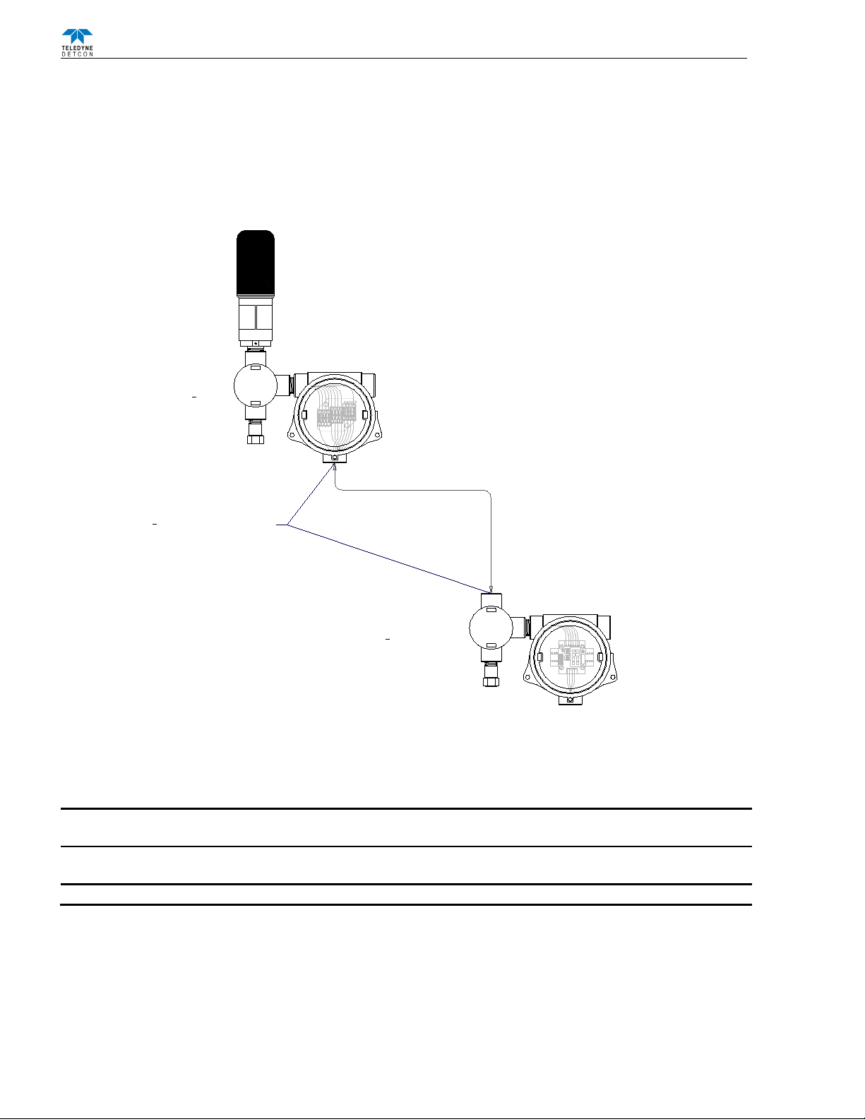
2.2.1 Remote Mounting
The RXT-320 wireless transceiver is normally connected directly to the J-Box containing the battery/terminal
board assembly. In situations where RF line-of-sight is diminished by obstructions, it may be necessary to
remotely mount the wireless transceiver away from this J-Box. Remote separation distances of up to 15 feet are
possible with the recommended cable. Such an installation will require an additional J-Box which connects to
the separated transceiver and houses Teledyne Detcon’s 12-position terminal board plus additional hardware
(See Figure 10).
Power,Modbus & I²C
Remote RXT-320 Wireless Transceiver
Extension Cable to/from
Remote RXT Transceiver
Up to 15' Length
J-Box w/
Model 100
Terminal Board
Remote J-Box w/
8-Position
Terminal Board
3
4
" NPT Cord Connectors
(Cable Glands) Required
SENSOR/
HMI
RBK WBU GN
J2
BU WBK RW/W/ BRBK
WIRE-
LESSJ1
J4
J6 J8
J3
TP2
mA - +
+ - SA
WB WA SB
J7
TP1
1 2 3
2
3
4
5
6
7
1
External DC
Power In
7-30VDC
Spare ModBus
RXT-320Transceiver
Slave Device/
Master Controller/
Remote Monitor
RXT Prog
Interface
LoopPowered
LEDDisplay
RXTP rog Port
( Detcon Use Only )
J5
Smart Battery Pack
W/
BU W/
GN W/V
3
4
" NPT T-Outlet
Box w/Drain
Remote
3
4
" NPT
T-Outlet Box w/Drain
Figure 8 RXT-320 Wireless Transceiver Remote Mounting
A custom extension cable needs to be built per Figure 11 to interface the remote transceiver to the Model 100
Terminal Board. The recommended cable for remote transceiver separation is Belden 1421A (24AWG shielded
twisted pair, 4 pairs w/drain wire).
NOTE: It is highly recommended to install the extension cable inside rigid metal conduit to eliminate
potential EMI and RFI interference and to maintain a Class I Division I rating.
NOTE: Color coding of the cable will no longer match the color coding on the Model 100 Terminal Board
for the J1 connector.
NOTE: Programming of RXT transceiver from the Model 100 Terminal Board will be disabled.

RXT-320 Wireless Instruction Manual Rev. 2.4 Page 9 of 26
J6
J7
J4
J1
J5
J8
L9
J2
AIN1
W/BK
W/BN
W/BU
W/GN
W/V
WIRELESS
AIN2
MA
GND
PWR
POWER IN
( SOLAR)
WIRELESS
PROGRAM
B
A
GND
24V
MODBUS OUT
( WIRELESS)
24V
GND
A
B
MODBUS IN
24V
GND
A
B
SENSOR
PWR
GND
SCL
SDA
SP1
SP2
DISPLAY
JP1
SW2
SW1
TERM
PROGRAM
BLACK - (GND)
RED (POWER)
BLUE (MODBUS A)
WHITE (MODBUS B)
BLACK (GND)
RED (POWER)
BLUE (MODBUS A)
WHITE (MODBUS B)
BLACK (GND)
RED (POWER)
BLUE (MODBUS A)
WHITE (MODBUS B)
MODEL 100
TERMINAL BOARD
RXT-320
TRANCEIVER WIRING
700-Series Transient
Protection PCA
Figure 9 Wiring Diagram for Remote RXT-320 Transceiver Mounting
2.3 Remote Mounting Steps
1. Remove the J-Box cover of the RXT-320 wireless transceiver assembly.
2. If the wireless transceiver assembly has the Smart Battery Pack, unplug the battery pack from the terminal
board by pulling the battery pack out of the junction box.
3. Identify the J1 6-pin phoenix connector and the J8 3-pin phoenix connector on the Model 100 Terminal
Board and disconnect from the board. Remove all transceiver wire connections from the connectors.
Reconnect the 3-pin connector to its corresponding place and save the 6-pin connector for step 13.
4. Use a wrench at the bottom section of the RXT transceiver and unthread the RXT until it can be removed.
5. Feed the RXT transceiver wires through the ¾” NPT hole of the remote T-Outlet box connected to the
remote J-Box and thread the transceiver into the remote T-Outlet box until tight.
NOTE: Wires that are not used should be individually capped off and secured out of the way in the T-Outlet
box so that they are not exposed to any active components, power, or ground.

RXT-320 Wireless Instruction Manual Rev. 2.4 Page 10 of 26
6. Remove all 6 of the 4-pin phoenix connectors from the 12-position terminal board in the remote J-Box and
connect the RXT transceiver wires to 3 of the phoenix connectors per the wiring diagram in Figure 11.
Reference Table 2 RXT-320 Transceiver Wire Identification for color code identification.
7. Reconnect these 3 phoenix connectors to their corresponding places back on the 12-position terminal board.
8. Measure out the cable to be used for the extension cable to be no more than 15 feet long. Feed one end of
the cable through a ¾” NPT cord connector (cable gland) and then into the ¾” NPT hole located on the
bottom of the remote J-Box.
9. Connect the cable wires of the extension cable to the remaining three 4-pin phoenix connectors from step 6
per the wiring diagram in Figure 11. Reference Table 1 Extension Cable Wire Identification for color code
identification.
10. Reconnect these 3 remaining phoenix connectors to their corresponding places back on the 12-position
terminal board and thread the ¾” NPT cord connector to the bottom of the remote J-Box.
11. Install the J-Box cover of the remote J-Box.
12. Feed the other end of the cable through another ¾” NPT cord connector and then into the ¾” NPT hole of
the T-Outlet box connected to the J-Box housing the Model 100 Terminal Board.
13. Connect the cable wires to the 6-pin phoenix connector from step 3 per the wiring diagram in Figure 11.
Reference Table 1 Extension Cable Wire Identification for color code identification.
14. Reconnect the 6-pin phoenix connector back to J1 of the Model 100 Terminal Board and thread the ¾” NPT
cord connector to the T-Outlet box
NOTE: Color coding of the cable will no longer match the color coding on the Model 100 Terminal Board
for the J1 connector.
NOTE: Programming of RXT transceiver from the Model 100 Terminal Board will be disabled.
15. Plug battery pack back in place and reinstall the J-Box cover from step 1.
Table 1 Extension Cable Wire Identification
Function
Color Reference
VDC Power (+)
Orange/White
VDC Return (-)
Green/White
Modbus A (+)
Blue/White
Modbus B (-)
White/Blue
Serial Clock (SCL)
White/Green
Serial Data Line (SDA)
White/Brown
Common Ground
White/Orange
Common Ground
Brown/White
Drain Wire
Bare (No Color)

RXT-320 Wireless Instruction Manual Rev. 2.4 Page 11 of 26
2.4 Wiring Connections/Functions
Dependent upon use and function, the RXT-320 wireless transceiver can be wired in different ways to different
devices. It is important to insure that the wiring is correct for the device to operate properly. Wire identification
for the transceiver can be found in Table 2 RXT-320 Transceiver Wire Identification.
Table 2 RXT-320 Transceiver Wire Identification
Function
Color Reference
VDC Power (+)
Red
VDC Return (-)
Black
Modbus™ A (+)
Blue
Modbus™ B (-)
White
Alarm 0
Brown
Alarm 1
Orange
Alarm 2
Violet
Alarm 3
Gray
4-20mA A
Green
4-20mA B
Yellow
Serial Clock (SCL)
White/Black
Serial Data Line Data (SDA)
White/Brown
Programming Data
White/Green
Programming Clock
White/Blue
Programming Reset
White/Violet
2.4.1 VDC Power & VDC Return
All RXT-320 wireless transceivers need to have DC power applied to the transceiver’s red (VDC power) and
black (VDC return) wires. The power requirements for the transceiver are such that the DC voltage input range
is 7 to 30 volts. This power will normally be supplied by the device the transceiver is connected to, but can
come from alternate DC sources such as the optional Smart Battery Pack, solar panel or external customer
supplied DC source.
NOTE: Power Source to the RXT-320 must be limited to max output of 15 watts.
If an external power source is installed, the RXT-320 wireless transceiver requires two conductor connections
for the power supply. External DC power can be customer provided with an output voltage range between 7 to
30VDC. Both of these alternatives will provide continuous operation of the assembly providing a constant
power source.
If the Model 100 Terminal Board option is not used, power to the transceiver should be directly applied to its
red and black wires accordingly. If the terminal board is used, wiring designations for power are ‘+’ and ‘-’
(External DC Power In) on the J5 connector of the Model 100 Terminal Board. The maximum wire length
between the transceiver assembly and a 24VDC source is shown in Table 3 Wire Gauge vs. Distance. The
maximum wire size for termination in the J-Box is 14 AWG.
Table 3 Wire Gauge vs. Distance
AWG Wire Dia. Meters Feet
Over-Current
Protection
22
0.723mm
700
2080
3A
20
0.812mm
1120
3350
5A
18
1.024mm
1750
5250
7A
16
1.291mm
2800
8400
10A
14
1.628mm
4480
13,440
20A
NOTE: Wiring table is based on stranded tinned copper wire and is designed to serve as a reference only.
NOTE: The supply of power should be from an isolated source with over-current protection as stipulated in
table. The output voltage range must be between 7-30VDC.
Before applying power, make sure that all wiring is correct. Not all wires from the wireless transceiver are used
in most configurations. Wires that are not used should be individually capped off and secured out of the way in
the T-Outlet that mounts the transceiver to the J-Box/condulet. This prevents exposure to any active
components, power or ground.

RXT-320 Wireless Instruction Manual Rev. 2.4 Page 12 of 26
2.4.2 ModbusTM A & B
The RXT-320 transceiver features a Modbus™ compatible communication port. The connections are Modbus™
A (blue wire) and Modbus™ B (white wire) and are polarity dependent. Modbus™ communication is
accomplished by two wire half duplex RS-485, 9600 baud, 8 data bits, 1 stop bit, no parity, through the
transceiver’s connection to the Modbus™ device. It is necessary to set a Modbus address for the RXT-320
unless operating in transparent mode.
2.4.3 Alarm 0-3
Each RXT-320 wireless transceiver provides outputs for up to four alarms (Alarm 0, Alarm 1, Alarm 2 and
Alarm 3) which can drive relays on custom terminal boards provided by Teledyne Detcon. There are four
internal Modbus™ registers that directly control these outputs. The outputs are open drain and rated for up to
300mA at 50V (See Figure 12). They are not intended to drive alarm devices directly, but rather to drive relay
coils (interposing relays) which in turn will drive a higher current output. Teledyne Detcon alarm terminal
boards are available that allow either AC or DC/Battery operation with the relays built onto the board. These
boards provide a complete solution to connecting an RXT-320 to power and providing high-current relay
closures. When using interposing relays, it is strongly recommended to install a transient protection diode
(1N4001) across the relay coil to mitigate the voltage spike when the coil is de-energized.
49.9K
RXT-320
Relay
Coil
Alarm Output
V+
1N4001
Diode
MOSFET N-CH
50V 300mA
From RXT-320
Processor Output
Interposing Relay
Figure 10 Internal Alarm Output Circuit
NOTE: External relays used with this circuit must not exceed voltage/current requirements and must have
transient protection to minimize the voltage spike when the coil is de-energized.
2.4.4 4-20mA A & B
The RXT-320 supports up to two 4-20mA signal inputs (A and B) used for monitoring 4-20mA devices (See
Figure 13). For the primary 4-20mA signal input, use A (green wire). For the secondary 4-20mA signal input,
use B (yellow wire). The input values are continuously read and stored in two separate registers accessible
through Modbus™ at the address assigned to the transceiver. Readings on a 4-20mA input are converted to
representative values, for example, 4mA is read as a value of 400 and 20mA is read as a value of 2000. These
inputs present a load of 162 ohms to ground so a current of 20mA will develop around 3.4V across the input and
ground. This will consume a third less power versus the 250 ohm load used in other implementations. The
inputs are protected for voltages up to 30V but the input reading will reach a maximum of 2048 for currents
greater than 20mA. Electrically the 4-20mA interface supports 2-wire and 3-wire devices.

RXT-320 Wireless Instruction Manual Rev. 2.4 Page 13 of 26
Figure 11 Up to two sensors using two 4-20mA interface
NOTE: The 4-20mA inputs do NOT support 4-wire implementations.
2.4.5 Serial Clock & Serial Data Line
This is the I2C interface for the transceiver consisting of a serial clock (SCL) and serial data line (SDA). These
are used to monitor the status of the battery pack (if installed) and to read the value of the Modbus™ address
switches of the Model 100 Terminal Board (if installed).
2.4.6 Programming Data, Clock & Reset
These connections are used to program the RXT-320 transceiver and should be used by Teledyne Detcon
personnel only.
2.5 Model 100 Terminal Board Settings
This section applies to transceiver assemblies that use the optional Model 100 Terminal Board. This terminal
board contains a set of jumpers that must be configured properly for the board to operate properly. These
jumpers are normally configured at the factory and should not be changed. Misplacement of these jumpers may
cause the transceiver to become inoperative. The following table describes the jumper positions.
Table 4 Model 100 Terminal Board Jumper Settings
Jumper
Setting
JP1
2-3
JP2
1-2
JP3
1-2
JP4
1-2
JP5
2-3
JP6
1-2
JP7
1-2
NOTE: These settings assume the RXT-320 is not being used with a Teledyne Detcon Model 100 sensor. If
the RXT-
320 is being used with a Model 100 sensor, these jumper settings may be different. Please refer to
the appropriate Model 100 manual for the correct settings.

RXT-320 Wireless Instruction Manual Rev. 2.4 Page 14 of 26
The Model 100 Terminal Board also contains two rotary switches which are used to set the Modbus™ address
for the RXT-320 wireless transceiver. The address selected is a two digit hex value with the MSD (most
significant digit) represented by the top rotary switch (closest to the J1 connector) and the LSD (least significant
digit) represented by the bottom rotary switch (closest to the J2 connector). For example, a hex value of ‘9F’
would be represented by a ‘9’ on the top switch and an ‘F’ on the bottom switch.
Figure 12 Model 100 Terminal Board Rotary Switches
NOTE: If using a Smart Battery Pack, battery pack removal is required to access the rotary switches for
Modbus™ addressing and to access the board jumpers.
Assigning a Modbus™ address to the transceiver allows registers within the transceiver itself to be accessed by
the master and provide additional control and status from that transceiver. Using these registers, the master
controller can control alarm outputs, read the two 4-20mA inputs, read battery life or put the network to sleep to
conserve battery. The address also determines the mode of operation for the transceiver. This will determine if
it is attached to a master controller or if it is attached to a slave device.
2.6 Remove From Service
CAUTION:Hazardous areas must be declassified before opening the junction box or removing and
replacing the RXT-320.
1. If powered from a DC power supply, remove source power from the device before opening the junction box
or proceeding with service work.
2. Open the junction box cover of the RXT-320 wireless transceiver assembly or installation.
3. If the wireless transceiver assembly has the Smart Battery Pack:
a) Remove the cap of the battery bracket assembly by loosening the two (2) thumb screws
b) Remove the battery pack
c) The entire battery bracket assembly must be removed to access the wiring. Remove the four (4)
Phillips head screws that secure the bracket assembly to the junction box, then carefully remove
the bracket assembly from the terminal board mounted inside the junction box.
4. Remove power to the RXT-320 by lifting the (red) +24VDC wire in the J-box.
5. Disconnect remaining RXT wires inside the junction box.
NOTE: If removal of the RXT results in disconnection of other wiring, ensure any unused wires are capped
off and secured out of the way in the T-
outlet or Junction Box such that they are not exposed to any active
components, power, or ground.
6. Use a wrench at the bottom section of the RXT transceiver and unthread the RXT until it can be removed.
7. Block any unused ports with suitable ¾” male NPT plugs, rated for Class I Division 1 Groups C & D
hazardous locations. See spare parts list (section 8.2) of Teledyne Detcon option.

RXT-320 Wireless Instruction Manual Rev. 2.4 Page 15 of 26
3. Operation and Configuration
The RXT-320 wireless transceiver assembly will power up as soon as power is applied. There is no external
power switch to the assembly.
NOTE: Before applying power, check to make sure that all the wiring connections and external devices are
installed correctly.
NOTE: Applying power with devices hooked up incorrectly may cause damage to the equipment.
The user will need to manually configure the Modbus™ address for the RXT-320 from the Model 100 Terminal
Board.If there is no Model 100 Terminal Board, the transceiver will have no address and function in transparent
mode. After the transceiver has been configured and powered up, it will begin normal operation. If the unit has
been configured properly, the unit will operate differently based on the address given from the terminal board
which is read once every five seconds using the I2C interface.
Table 5 RXT-320 Addressing and Operational Modes
Modbus
Address (hex)
RXT-320 Function
00
Transparent Mode
F0
Master
01-7F, 90-DF
Slave
80-8F, E0-EF
Alarm Station
F8-FF
Reserved per Modbus™
3.1 Transparent Mode
In transparent mode, the RXT-320 wireless transceiver behaves like a wired Modbus™ device in that any data
transmitted over Modbus™ will be passed on over the RF network and be broadcast to all other RXT-320’s in
the wireless network and presented on their respective Modbus™ interface. The transparent mode is achieved
by setting the transceiver’s Modbus™ address equal to 00h through the transceiver’s terminal board. If the
Model 100 Terminal Board is not installed, the transceiver will default to an address of 00h. The transceiver
will behave as neither a master nor slave and its internal RXT-320 registers can not be accessed. Any devices
connected to a transceiver in transparent mode will receive all controller requests via the Modbus™ interface
and a response by the device will occur only if its Modbus™ address is equal to the request address. If so, the
device will respond back to the transceiver via Modbus™ which will then send the response back to the controller
over the RF network.
NOTE: Transparent mode does not support accessing the internal registers of the transceiver through
Modbus™ since there is no address assigned. Consequently many features are not available such as sleep,
battery status, 4-20mA inputs and alarm outputs.
3.2 Slave Configuration with Controller
The RXT-320 wireless transceiver can function as a master when connected to a controller by assigning it a
Modbus™ address of F0h through the transceiver’s Model 100 Terminal Board. In this configuration, the
controller can send out requests and receive data/status from slave devices over the wireless network through its
Modbus™ interface to the transceiver. The transceiver’s local Modbus™ interface is set up to be a slave
interface to the master controller which means the transceiver will act as a slave to the controller but be seen as
the master globally. Requests from the controller will be received by the transceiver through the Modbus™
interface and the transceiver will transmit the request over the RF network to all RXT-320’s. If the slave device
being commanded is found, a response will be generated which will be received by the master transceiver over
the RF network and sent back to the controller via the local Modbus™ interface.
3.3 Slave Configuration with Sensor
The RXT-320 wireless transceiver can also function as a slave when connected to a slave device (sensor) by
assigning it a Modbus™ address that is not equal to F0h (controller) or 00h (transparent mode). This Modbus™
addressing will affect how the slave RXT-320 deals with the request it receives. In this configuration, the
transceiver can receive requests and send out data/status over the wireless RF network. The transceiver’s local

RXT-320 Wireless Instruction Manual Rev. 2.4 Page 16 of 26
Modbus™ interface is set up to be a master interface to the slave device which means the transceiver will act as
the master to the sensor attached but be seen as a slave globally. Modbus™ addressing will dictate how the
transceiver deals with a request.
If the Modbus™ address in the request does not equal the address assigned to the RXT-320, the transceiver
simply sends along the request unchanged on to its Modbus™. It will behave similar to transparent mode. The
request will be responded to if a sensor with an address equal to the address in the request is found. If so, the
sensor will respond back to the transceiver via Modbus™ which will then send the response back to the controller
over the RF network.
If the Modbus™ address in the request equals the address assigned to the RXT-320 and does not fall within the
RXT-320 internal registers, the transceiver will translate the Modbus™ address to 01h and send along the request
on its Modbus™ interface with the new translated address. This translate function allows a single DM-100
sensor to be installed per each RXT-320 since all DM-100 sensors have a fixed address of 01h. If a sensor with
an address of 01h is found, it will respond back to the transceiver via Modbus™. The transceiver will then
translate the 01h address back to its original value and send the response back to the controller over the RF
network.
If the Modbus™ address in the request equals the address assigned to the RXT-320 and falls within the RXT-
320 internal registers, the transceiver will not translate. The transceivers RXT-320 registers will be accessible
and it will respond back to the controller over the RF network without ever having put any data on the
transceivers Modbus™ interface. Any sensors connected to the transceiver would never see the request.
3.4 Slave Configuration with Alarm Station
Another function of the RXT-320 wireless transceiver is as an alarm output device when connected to an alarm
station. Each RXT-320 provides up to four alarm outputs (Alarm 0, Alarm 1, Alarm 2 and Alarm 3) which can
drive relays on custom terminal boards provided by Teledyne Detcon or interposing relays provided by the
customer. These outputs are not intended to drive alarm devices directly due to their low current output, but
rather to drive relay coils which in turn will drive a higher current output. There are four RXT alarm output
registers that become available when in alarm station mode. The four alarm outputs are controlled by four
internal registers within the RXT-320 and can be controlled on all RXT-320 transceivers by writing to these four
registers using the Modbus™ address assigned that transceiver.
If the RXT-320 transceiver is assigned a Modbus™ address between (80h-8Fh) there will be a duplicate set of
four registers available to control the alarm outputs. These are introduced for compatibility with some
controllers.
NOTE: If the transceiver is assigned a Modbus™ address between E0h-EFh on the Term board the RXT-
320 will remap its address to the 80h-8Fh address respectively and function the same way.
3.5 Sleep Mode
A sleep mode is available to increase the battery life of the RXT-320 transceiver assemblies that have them.
Upon command from the Modbus™, all RXT-320 transceivers will turn off their wireless radios for the
requested period of time. During this time there will be no communication possible with other RXT-320
transceivers. The command is given through a single Modbus™ broadcast command (Modbus™ address of 0)
with the number of seconds to go to sleep. Every RXT-320 transceiver that receives this command will turn off
their on-board radio and count down the seconds until it reaches zero at which time the radios will be turned
back on. The controller can query the sleep timer on its own transceiver to determine how many seconds are
left and can begin Modbus™ communication when it reaches zero.
NOTE: Sleep mode is not supported by transceivers that are in transparent mode since no address is assigned
and therefore its internal registers are not accessible through Modbus™.
When the RXT-320 transceiver radio is put to sleep it will reduce the RXT-320 power consumption by about
90%. This of course does not include other devices running off of the battery, only the transceiver. Generally
the controller will put the network to sleep after all devices have been polled on the network. While the network
is asleep, there are no devices being read so the user will have to trade off power consumption versus the time
between updating/reading a device on the network.
Table of contents


 Service manual")


