Intel Arria 10 SX User manual

©2017 Intel Corporation. All rights reserved. ALTERA, ARRIA, CYCLONE, HARDCOPY, INTEL, MAX, MEGACORE, NIOS,
QUARTUS and STRATIX words and logos are trademarks of Intel Corporation and registered in the U.S. Patent and Trademark
Office and in other countries. All other words and logos identified as trademarks or service marks are the property of their respective
holders as described at www.altera.com/common/legal.html. Intel warrants performance of its semiconductor products to current
specifications in accordance with Intel's standard warranty, but reserves the right to make changes to any products and services at
any time without notice. Intel assumes no responsibility or liability arising out of the application or use of any information, product, or
service described herein except as expressly agreed to in writing by Intel. Intel customers are advised to obtain the latest version of
device specifications before relying on any published information and before placing orders for products or services.
Date: 8/29/2017
Revision: 1.1
Arria 10 SX Triple-rate SDI with Transceiver Toolkit
Reference Design User Guide

2
Table of Contents
Introduction....................................................................................................................................................3
Requirements................................................................................................................................................3
Theory of Operation ......................................................................................................................................5
How to Setup the Hardware for Link Test.....................................................................................................8
How to Reconstruct and Running the Reference Design.............................................................................8
Conclusion...................................................................................................................................................16
References..................................................................................................................................................16
Revision History..........................................................................................................................................16

3
Introduction
The objective of this design example is to demonstrate how to dynamically perform PMA analog settings
tuning in a Triple-rate SDI link using transceiver toolkit. This design comes with SDI pattern generator up
to 3G video mode which allow the loopback test from SDI TX to RX. It also equipped with In-System
Source and Probe (ISSP) instance to allow real-time interface with the SDI link and for TRS and Frame
lock monitoring. With the help of transceiver toolkit, user will be able to use the GUI to change the PMA
analog settings supported by the Arria® 10 transceiver as well as perform Auto-sweep to find the
optimal settings for a SDI link. The design will also show a link test between SDI TX And RX channels as
well as and PMA analog settings tuning in Arria 10 SoC Development Kit
Requirements
The reference design requires the following hardware and software to run the test:
•Quartus® Prime Software Version: 16.0
•Arria 10 SoC Development Kit
https://www.altera.com/products/boards_and_kits/dev-kits/altera/arria-10-soc-development-
kit.html
•FPGA Mezzanine Card (FMC) to High Speed Mezzanine Card (HSMC) adapter board
http://www.kayainstruments.com/fmc2hsmc/
•Terasic SDI HSMC Board
http://www.terasic.com.cn/cgi-
bin/page/archive.pl?Language=English&CategoryNo=66&No=343
•One BNC cable

4
Figure 1. Arria 10 SoC Development Kit

5
Theory of Operation
Figure 2. Block diagram of modules in the reference design
Figure 2 shows the high-level modules in the reference design as well as the interfaces among the
modules. The A10 transceiver Native PHY is used to configure and implement the hard transceiver
channels. The SDI II Triple-rate IP would perform the SDI protocol operation. The transceiver
reconfiguration management module will perform the dynamic rate change to support different video
modes for triple-rate SDI. The SDI II Triple-rate IP will perform auto rate switch to lock to the incoming
video mode from SD-SDI up to 3G SDI. This SDI pattern generator support video pattern up to 3G SDI
video mode which allow the loopback test from SDI TX to SDI RX for TRS and Frame lock monitoring. You
can select different video patterns by controlling the sw[3..0] in the ISSP instance -
Spf_sample_design_ttk.spf.

6
The following table shows the mapping of the sw[3..0] in the Spf_sample_design_ttk.spf to the video
patterns:
sw[3..0]
Video Pattern
4'b0000
SD NTSC
4'b0001
SD PAL
4'b0010
HD 1080i60
4'b0011
HD 1080i50
4'b0100
HD 1080p24
4'b0101
HD 720p60
4'b0110
HD 720p30
4'b0111
HD 1080p30
4'b1000
HD 1080p25
4'b1001
3Ga 1080p60
4'b1010
3Ga 1080p50
4'b1011
3Gb 2x1080i60
4'b1100
3Gb 2x720p30
4'b1101
3Gb 2x1080p30
4'b1110
3Gb 1080p60
4'b1111
3Gb 1080p50
Table 1. SDI Video Pattern Generator Mapping
You may also refer to the video_pattgen_top.v for further details on the mapping. The status monitoring
is done using the probes in the ISSP instance - Spf_sample_design_ttk.spf as well. Figure 3 shows an
example of the TRS lock and frame lock monitor.
Figure 3. ISSP Probes for Status Monitoring Example

7
Transceiver toolkit is generally used to find the optimal PMA analog settings of the transceiver for a
board setup. Transceiver toolkit comes with user interface to allow user to real time interface through
with the transceiver as well as dynamically change the PMA analog settings on-the-fly by just clicking
buttons. User will just need to select a specific PMA analog value from the drop-down list and the toolkit
will help to perform the background dynamic reconfiguration steps. With the help of transceiver toolkit,
user will be able to perform Auto-sweep to find the optimal settings for a link. Figure 4 shows an
example of the transceiver toolkit GUI and the VOD settings drop-down list.
Figure 4. Transceiver Toolkit UI And VOD Settings Drop-down List
Since there is no HSMC connector available on the Arria 10 SoC Development Kit, the FPGA Mezzanine
Card (FMC) to High Speed Mezzanine Card (HSMC) adapter board is used to allow connection with the
SDI HSMC Board. The BNC cable is then used to form a loopback link from the SDI TX to SDI RX to
perform the loopback test. Figure 5 shows an example of the connection of the boards and BNC cable.

8
Figure 5. Board Setup for SDI Link Loopback Test
How to Setup the Hardware for Link Test
Follow these steps to setup the hardware to run the reference design:
1. Connect the FPGA Mezzanine Card (FMC) to High Speed Mezzanine Card (HSMC) adapter board
to FMC B daughtercard port of the Arria 10 SoC Development Kit
2. Connect the SDI HSMC Board to the HSMC connector of the FMC to HSMC adapter board
3. Connect one BNC cable from SDI OUT2 to SDI IN2 on the SDI HSMC Board
4. Use the default switching settings. For more details about default switching settings, please
refer to Arria 10 SoC Development Kit user guide
5. Connect the USB cable to the USB Blaster connector on the development kit
6. Connect the power adapter shipped with the development board to power supply jack
7. Turn On the power for the Arria 10 SoC Development Kit. The hardware system is now ready for
programming
How to Reconstruct and Running the Reference Design
Follow these steps to reconstruct, compile and run the design:
1. Follow the instruction in the Design Store to prepare the design template and load the design
into your Quartus software
2. By default, the frequency of SDI refclk oscillator on the Arria 10 SoC Development Kit is
148.35Mhz. Do the following changes to a10_top.v to change the frequency to 148.5MHz:
a. Add "output si516_fs, // 0 - 148.35MHz, 1 - 148.5MHz" to input/output ports
declaration section of the a10_top.v
b. Add "wire sdi_clk_sel;" and "assign si516_fs = ~sdi_clk_sel" to the wire declaration
section of the a10_top.v

9
c. Replace ".source_export ({reconfig_rst, ISSP_sw[3:0]}), // source.export" with
".source_export ({sdi_clk_sel,reconfig_rst, ISSP_sw[3:0]}), // source.export" in the
a10_top.v
d. Add “set_location_assignment PIN_AL22 -to si516_fs” to a10_top.qsf
3. Perform full compilation with the design
4. Program the SOF file generated into the Arria 10 SoC Development Kit
5. After the programming is completed, open the Spf_sample_design_ttk.spf file and establish
connection to the device
6. Click on the Continuously Read Probe Data to start signal sampling
7. In the following discussion, we will be using the 3G SDI example to ease the discussion
8. In the Spf_sample_design_ttk.spf, set the sw[3..0] to select the 3Ga 1080p60 video pattern. The
video pattern generator will start to generate this pattern to the SDI RX
9. The SDI RX will perform auto rate change and lock to the incoming video pattern. After
successfully link up, you should now observe the rx_frame_locked and rx_trs_locked status
signals assert as shown in Figure 6
10. To perform the transceiver PMA analog settings tuning, open the transceiver toolkit at Quartus -
> Tools -> System Debugging Tools -> Transceiver Toolkit
11. Load the design SOF file in the transceiver toolkit to establish link with the transceiver at
Transceiver Toolkit -> File -> Load Design as shown in Figure 7
12. Click on the Transceiver Toolkit -> Transceiver Links -> Control Transceiver Link to establish
control over the TX and RX as shown in Figure 8
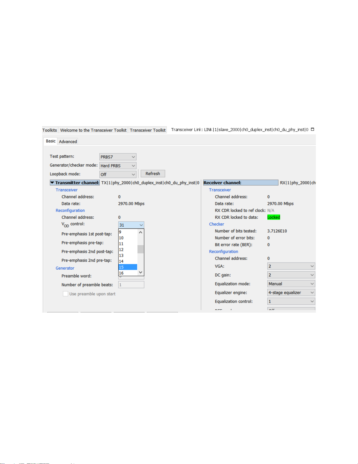
13. After the transceiver link control established, you can click on the drop-down list of the TX and
RX PMA analog settings to dynamically change the values. For example, you can change the TX
VOD settings as shown in Figure 9.
14. By using the transceiver toolkit GUI, you can dynamically change the PMA settings to fine tune
the signal integrity of the SDI link. This would be the manual way of tuning
15. Transceiver toolkit also supports the Auto-sweep feature to help finding optimal PMA analog
settings for your link
16. During the Auto-sweep process, the transceiver toolkit will be sending PRBS data pattern
through the transceiver TX. Due to the PRBS pattern, the SDI RX will lose lock and keep changing
its rate in attempt to lock to the incoming data
17. Before running Auto-sweep with Transceiver Toolkit, send a 3G TX video pattern to the RX so
that the RX is reconfigured to 3G mode
18. To allow transceiver toolkit to take full control of the transceiver and avoid the RX being reset
and reconfigured by SDI II IP, go to the Spf_sample_design_ttk.spf, set the reconfig_rst signal to
High as shown in Figure 10
19. Go to Advanced -> Auto-sweep. Set the PMA analog settings to a specific range then click Start
to start the Auto-sweep. Figure 11 shows an example of sweeping VOD values from 0 to 30
20. As the Auto-sweep run, the transceiver toolkit will record the best value found for the PMA
settings as shown in the Figure 12
21. You may then port these optimal values to your design through Assignment Editor or QSF

10
22. If require, you may then further manually fine tune by using the values found by transceiver
toolkit as starting points
Figure 6. The rx_frame_locked and rx_trs_locked Signals Assert after Successful Locking to the 3G SDI
Signal

11
Figure 7. Loading SOF File in Transceiver Toolkit

12
Figure 8. Establish Control to the Transceiver Link

13
Figure 9. Dynamically Change the TX VOD Settings
Figure 10. Hold the SDI RX Transceiver Rate Change

14
Figure 11. Transceiver Toolkit Auto Sweep for a VOD Range

15
Figure 12. Optimal Setting by Transceiver Toolkit Auto Sweep

16
Conclusion
The design example provides a reference on how to dynamically perform PMA analog settings tuning in
a Triple-rate SDI link using transceiver toolkit.
References
•Triple-Rate SDI II Simple Design
http://www.alterawiki.com/wiki/Triple-Rate_SDI_II_Simple_Design
•SDI II IP Core User Guide
https://www.altera.com/documentation/bhc1410937441525.html
•Arria 10 Transceiver PHY User Guide
https://www.altera.com/content/dam/altera-www/global/en_US/pdfs/literature/hb/arria-
10/ug_arria10_xcvr_phy.pdf
Revision History
Date
Version
Changes
August 29, 2017
1.1
Update instructions to
configure refclk frequency and
to run tuning with TTK
May 7, 2017
1.0
Initial Release
Table of contents
Other Intel Transceiver manuals