TELELYNX IDH2-3000 Series User manual

MODEL IDH2-3000
MULTI CHANNEL

-2-
S
Sa
af
fe
et
ty
y
I
In
ns
st
tr
ru
uc
ct
ti
io
on
ns
s
Read this manual carefully before start operating the device.
Removal of device cover without permission may cause harm to human body and
the maintenance bond to be invalidated.
Handle the device with care to avoid crashing and falling, or otherwise it may cause
hazards to the internal hardware parts.
Keep all inflammable, metal and liquid materials from dropping into the device
casing, or otherwise it may cause damages to the device.
Avoid dusty places and places with heating resources nearby, direct projection of
sunlight or instant mechanical vibrations for installation of the device.
Connect the grounding connector on the rear panel to protective earth contact
properly while in operation.
Choose proper type of cable connectors for connecting network interfaces of the
device.
Avoid rapid and frequent power on/off, or it may cause damages to the
semiconductor chipsets.
Keep proper direction of the power cord when plug into or out from a power socket.
Connect the grounding pole and signal cable before connecting the power cord.
Do not touch the power socket with wet hands to avoid electric shocks.
Take off all jewelry or ornaments, such as ring, necklaces, watches, bracelets, etc.,
before operating the device, or otherwise the metal contact may possibly cause
short circuit and result in components damage.
Make sure the AC power is unplugged in case of operator services within the
device casing or close to power supply are needed.
Only TELELYNX trained and approved staff is permitted to perform live line
operation and maintenance within the device casing.
Ensure good ventilation when the device is in operation, or otherwise it may cause
damages to the device due to overheating.
It is recommended to unplug the power cord from the socket if the device will not be
used for a long period of time.

-3-
Table of Contents
Safety Instructions............................................................................................................................2
Table of Contents.............................................................................................................................. 3
§1 Introduction .................................................................................................................................5
§1.1 Functionality.....................................................................................................................5
§1.2 Main Features................................................................................................................... 5
§1.3 Front Panel........................................................................................................................ 6
§1.4 Rear Panel......................................................................................................................... 6
§2 Before Use the Device.................................................................................................................8
§2.1 Operation Requirements...................................................................................................8
§2.1.1 Requirements for Digital TV Devices ...................................................................8
§2.1.2 Requirements for Network Devices....................................................................... 8
§2.2 System Requirements .......................................................................................................8
§3 Operating the Device...................................................................................................................9
§3.1 Quick Start........................................................................................................................9
§3.2 Web Management Operations of IDH2-3000 Series ......................................................10
§3.2.1 User Login...........................................................................................................10
§3.2.2 User Management................................................................................................ 12
§3.2.2.1 Add new user ............................................................................................ 12
§3.2.2.2 Edit users’ information.............................................................................. 13
§3.2.2.3 Delete an user............................................................................................14
§3.2.3 Basic parameter setting........................................................................................ 15
§3.2.3.1 IP Settings................................................................................................. 15
§3.2.3.2 MAC address setting................................................................................. 16
§3.2.3.3 Parameter setting about system clock....................................................... 16
§3.2.4Advanced Parameter setting.................................................................................17
§3.2.4.1 Import/export/reset the parameters........................................................... 17
§3.2.4.2 Back-up/recover the parameters ...............................................................19
§3.2.4.3 Upgrade/back-up the software.................................................................. 20
§3.2.4.4 Device authorization.................................................................................21
§3.2.4.5 Device control........................................................................................... 21
§3.2.5 Input/output setting.............................................................................................. 23
§3.2.5.1 IP Settings................................................................................................. 23
§3.2.5.2 Configuration of the Modulation channel................................................. 24
§3.2.6 Multiplexing setting of Programs ........................................................................26
§3.2.6.1 General setting..........................................................................................27
§3.2.6.2 PID mapping function...............................................................................28
§3.2.6.3 PSI information insertion..........................................................................30
§3.2.6.4 NIT edit..................................................................................................... 32
§3.2.6.5 Input Service.............................................................................................35
§3.2.6.6 Output service...........................................................................................39
§3.2.7 Scrambling Setting............................................................................................... 44
§3.2.7.1 General Setting .........................................................................................45
§3.2.7.2 CAS Configuration...................................................................................45
§3.2.7.3 Services Scrambling Setting..................................................................... 47
§3.2.8 Monitoring........................................................................................................... 49
§3.2.8.1 Alarms....................................................................................................... 50
§3.2.8.2 Bitrate Monitor ......................................................................................... 52

-4-
§3.3 Front Panel Operation of IDH2-3000 Series ..................................................................54
Annex A: Technical Specifications of IDH2-3000 Series ..............................................................56
Annex B: QAM Reference Information ......................................................................................... 58
Annex C: FrequentlyAsked Questions........................................................................................... 59
-5-
§
§1
1
I
In
nt
tr
ro
od
du
uc
ct
ti
io
on
n
§
§1
1.
.1
1
F
Fu
un
nc
ct
ti
io
on
na
al
li
it
ty
y
IDH2-3000 Series is a new generation of Multifunctional Modular IP Multiplexer-Scrambler-QAM
modulator, which can receive TS from the three IP interfaces, and then multiplex, scramble and process
it with channel coding. It adopts our newly developed functions such as “Module Management”, device
scrambling, and channel modulation. The flexible customization and high expansibility can satisfy the
user’s current and future DTV system requirements.
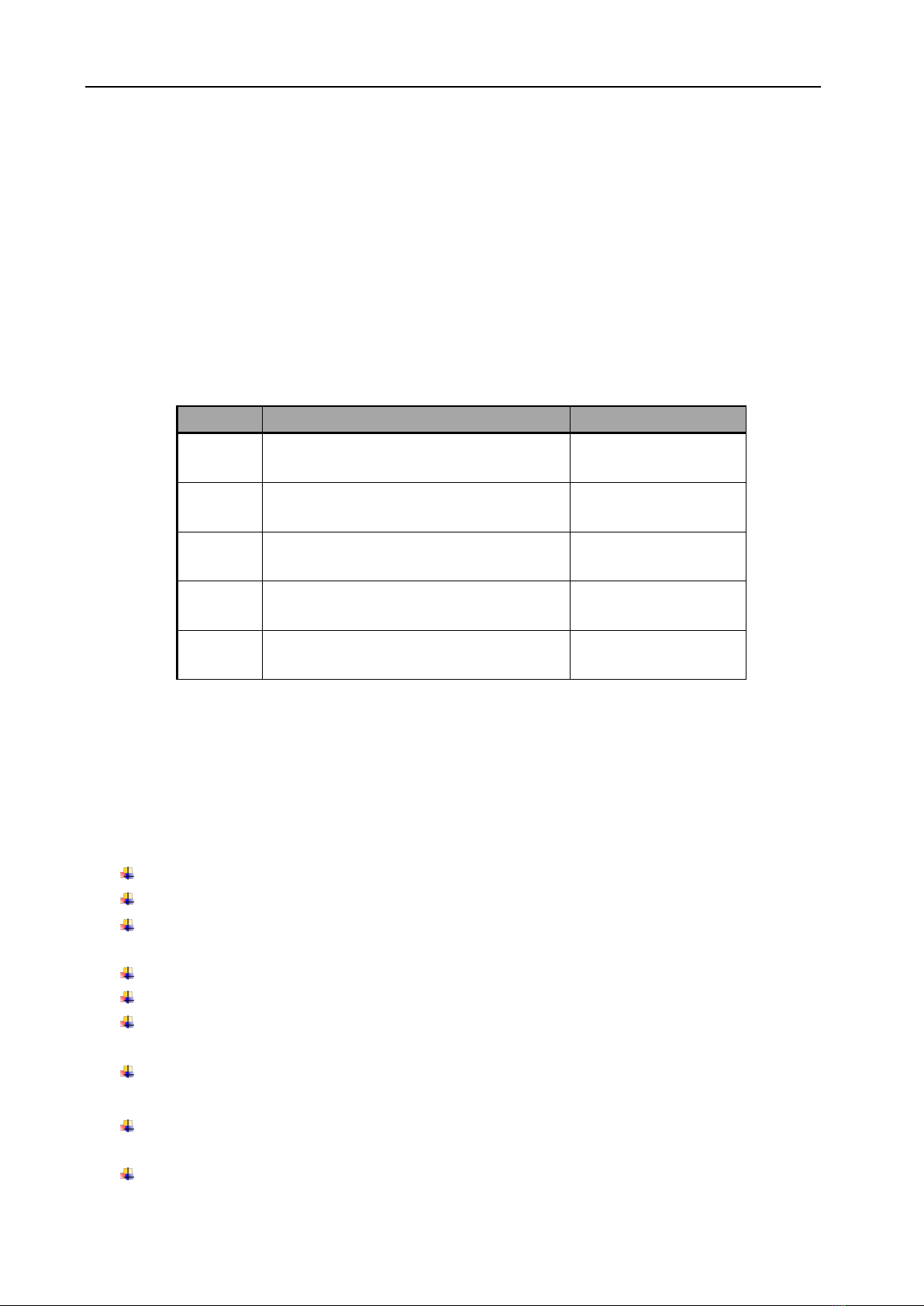
The module management opens the scrambling function and configures the numbers of output
modulation channel through software authorization, as shown in the table below:
Item
Function
Remark
Level 1
No scarmble
Level 2
1CAS scramble
CA1
Level 3
2CAS scramble
CA2
Level 4
3CAS scramble
CA3
Level 5
4CAS scramble
CA4
Table 1 License Type List
The product is mainly applied to the DTV network head end room, edge of DTV backbone network, and
DTV branch head end room.
§
§1
1.
.2
2
M
Ma
ai
in
n
F
Fe
ea
at
tu
ur
re
es
s
This product has the following key features:
Support ITU-T J.83A/B/C, output frequency range: 54 MHz ~ 860 MHz
Capable of working with 16QAM, 32QAM, 64QAM, 128QAM, 256QAM modulation methods
The single device offers multiple configurations, and also can be released by software
authorization
Support up to 4 simul-crypt CAS and DVB-CSA scrambling
Support SI/PSI auto-generation and manual uploading during re-multiplexing
Support auto-generation or manual editing of network information, as well as local network
information sectors uploading
Adopt extra-large cache memory for both constant and inconstant input bit stream at IP
interface
Flexible network configuration, support input stream auto-detection and user configuration
auto-saving
Support PID filtering,pass-through and PCR auto-correction
-6-
PCR auto-correction
Four adjacent frequency output for selection
Bit rate range of single output data: 15.5~51.6Mbps
Output data symbol rate range of single RF channel: 4.2~7Mbaud/s
Output EPL range: 95 dBuV~115 dBuV (8 channels, step size: 0.25 dB)
Support gain fine-tune and in-band EPL balancing, EPL adjustment range: -2.5~10.5 dB
Support -20dB RF test port
Tracking filter circuit design to ensure outstanding out-of-band rejection
Support device configuration import/export
Support Web/SNMP-based management and online remote update
Multi-lingual management user interfaces and related documents, suit for both regional and
overseas markets
Support monitoring of operation temperature and power supply status
* Please refer toAnnex A for detailed technical specifications.
§
§1
1.
.3
3
F
Fr
ro
on
nt
t
P
Pa
an
ne
el
l
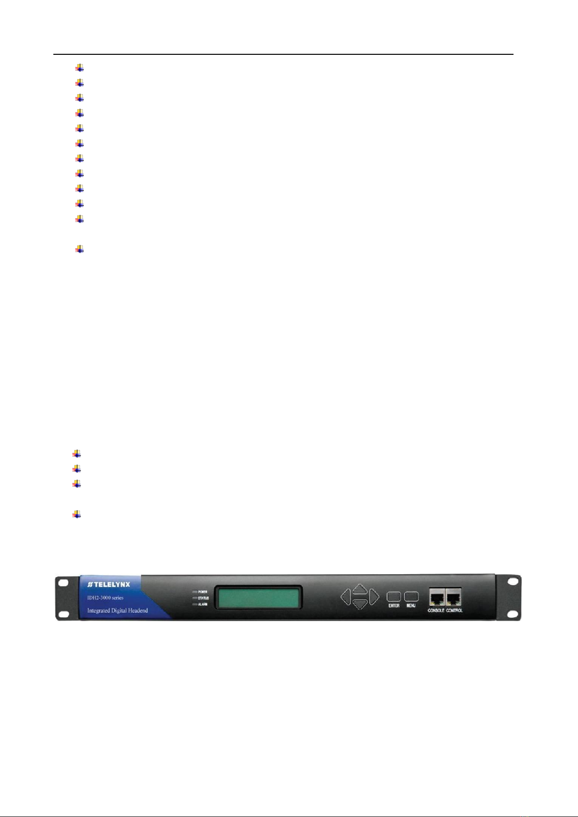
As shown in figure 1, there are one LCD display, one 6-key keypad and three LED indicators on the front
panel of IDH2-3000 Series.
The model type and logo information will be displayed on the LCD screen during the device initialization
stage. User can check some major working status of the device, and configure some key parameters of
IDH2-3000 Series by exploring the operational menu using buttons and LCD screen after system
initialization, see section §3.3 for details.
The POWER LED will be light if the device powers on successfully.
The STATUS LED will show some working status of the device, see section §3.3 for details.
The ALARM LED will indicate warning messages of the device, if exists, see section §3.3 for
details
Management Port: Two RJ45 connectors, The CONTROL is used to device management to
connect to management workstation via 100BaseT or Gigabit Ethernet; The CONSOLE port is
used for engineering debug purpose only;
Fig.1 Front Panel View of IDH2-3000 Series
§
§1
1.
.4
4
R
Re
ea
ar
r
P
Pa
an
ne
el
l
As shown in figure 2, the rear panel of IDH2-3000 Series consists of one power supply socket, one
power switch, one RJ45 management port, two ASI inputs, two RF outputs (main output and testing
output), and a grounding point.

-7-
Power Input Port: To connect to 100~240V 50/60Hz AC input;
Power Switch: To turn IDH2-3000 Series on or off;
DATA port: two RJ45 GbE connectors, to connect TS IP input from proceeding devices and TS IP
output to succeeding devices via ultra 5 cable or category 6 cable; The DATA port should be
connected with L3 switch in the IP head end installation.
RF Outputs: RF-OUT port is used to connect IDH2-3000 Series’output signal to digital CATV system,
HFC network or digital terrestrial transmission station via coaxial cables; the RF-20dB port is used
for monitoring.
Grounding Point: it connects the device with conductive earth. Please make sure of proper
grounding of the device before start operating it for the safety of the operators and the device itself!
Fig.2 Rear Panel View of IDH2-3000 Series

-8-
§
§2
2
B
Be
ef
fo
or
re
e
U
Us
se
e
t
th
he
e
D
De
ev
vi
ic
ce
e
§
§2
2.
.1
1
O
Op
pe
er
ra
at
ti
io
on
n
R
Re
eq
qu
ui
ir
re
em
me
en
nt
ts
s
In order to ensure proper operation of IDH2-3000 Series, there are some requirements for other digital
TV and network devices, which will connect with IDH2-3000 Series. Please see below for details:
§
§2
2.
.1
1.
.1
1
R
Re
eq
qu
ui
ir
re
em
me
en
nt
ts
s
f
fo
or
r
D
Di
ig
gi
it
ta
al
l
T
TV
V
D
De
ev
vi
ic
ce
es
s
The output signals of the IDH2-3000 Series should comply with DVB-C modulation standard, and the
signal frequency range is from 30MHz to 860MHz.. The device which will receive output signal from
IDH2-3000 Series, should comply with the following standards:
Transport Stream (TS): This means that the TS stream with one or more channels of digital TV, digital
audio broadcasting or any other digital TV services should comply with DVB standard; it must contain
PAT and PMT tables, which can completely describe the services.
The TS stream could be transmitted through ASI/Ethernet interface. For output IP interface, the TS
packets must be encapsulated into UDP datagram. Each output TS should have unique destination IP
address (unicast or multicast) and port number. The length of the UDP payload must be 7*188Byte (TS
packets), and the payload must be synchronized by sync byte 0x47. The TS stream (except the stream
with UDP format) also can be output fromASI interface, with standard format of 188 byte.
IDH2-3000 Series may be able to receive multiple transport streams from any devices with the TS format
complies with the above-mentioned format.
§
§2
2.
.1
1.
.2
2
R
Re
eq
qu
ui
ir
re
em
me
en
nt
ts
s
f
fo
or
r
N
Ne
et
tw
wo
or
rk
k
D
De
ev
vi
ic
ce
es
s
The switch used to connect IDH2-3000 Series’management port and the management workstation
should be a 100BaseT or Gigabit switch, the maximum data exchange speed of each port must be
higher than 40Mbps. For simplified installation, it can be the same switch of data inputs as well, but the
two ports need to be configured in different VLANs.
§
§2
2.
.2
2
S
Sy
ys
st
te
em
m
R
Re
eq
qu
ui
ir
re
em
me
en
nt
ts
s
Management workstation must have network connection and support TCP/IP protocol. Microsoft
Windows 2000/XP (or higher versions) and Internet Explorer 9.0 (or higher version) are the
recommended operating systems of the management workstation, and JavaScript must be supported by
the web browser.

-9-
§
§3
3
O
Op
pe
er
ra
at
ti
in
ng
g
t
th
he
e
D
De
ev
vi
ic
ce
e
§
§3
3.
.1
1
Q
Qu
ui
ic
ck
k
S
St
ta
ar
rt
t
Please follow the procedures below if it is the first time for you to use IDH2-3000 Series for constructing
digital TV head-end system:
1. Construct your hardware environment, including chassis installation, power supply system
deployment, and connecting switches, IDH2-3000 Series, the preceding device(s)(e.g. IRD,
encoders, etc.), terminal receivers (DVB-C), TV monitors, management workstation and CAS server
properly (refer to Fig. 3).
2. Plan for the IP addresses of management port and data port, the cable connectors (ultra 5 cable, RF
signal cable) of each preceding/succeeding devices; as well as number of digital TV transport
streams, modulating frequency of each stream, symbol rates and modulation methods. It is strongly
recommended to take remark of device addresses, port numbers and other configurations and keep
it safely for checking purposes in future.
3. Boot up each preceding devices of IDH2-3000 Series and configure the operating parameters, in
order to ensure the proper signal receiving/decoding or output of encoded digital TV transport
streams. Please refer to the user manuals of preceding devices provided by their suppliers for
detailed configuration.
4. Boot up IDH2-3000 Series, If you have known the management port IP address of the IDH2-3000
Series you are currently using, and it is in the same subnet with the management workstation, you
may also start configuring IDH2-3000 Series from the management workstation directly. Or
otherwise you will need to configure the IP address of management port using front panel control
5. Login to the web browser from the management workstation, key in the default user name “admin”
and password “000000”; add and configure usernames and passwords of users allowed to access
the device (refer to section§3.2.2 )
6. Configure the data input/output ports, modulated output channels, QAM mode, RF output frequency,
EPL and so on(refer to section§3.2.2 )
7. Search for input services tree (refer to section §3.2.6.5), configure the output program settings of
IDH2-3000 Series, including: select input service for output stream(refer to section), output program
scrambling; configure the ES PID, ECM/EMM PID, SI/PSI version number of each program, and
configure the auto-generated SI parameters or upload SI segments output program parameter;
configure the PID mapping parameters if needed.
8. If there are scrambled programs in the system, you need configure the CA operating parameters as
well..
9. Configure the signal receiving and demodulation settings of IDH2-3000 Series’succeeding devices
(e.g. DVB-C receivers) according to the user manuals provided by their suppliers
10. Make use of TS analyzer, QAM analyzer, spectrum analyzer, set-top box testing system, etc. to test
the output TS in the head-end equipment room, if normal, then the signal is ready for transmission in
the real network.

-10-
§
§3
3.
.2
2
W
We
eb
b
M
Ma
an
na
ag
ge
em
me
en
nt
t
O
Op
pe
er
ra
at
ti
io
on
ns
s
o
of
f
I
ID
DH
H2
2-
-3
30
00
00
0
S
Se
er
ri
ie
es
s
Monitoring and control of IDH2-3000 Series are available through Web browser. We recommend you to
use Microsoft Internet Explorer 6.0 or above and set your screen resolution to 1024 * 768.
The default state of Web management page is in English. If you want to use Chinese, please set the
language to Simple Chinese by changing the operation language in the pull-down list in the home page.
Fig.3 Operation language pull-down list
When you set this to Chinese, if there isn’t any Chinese font in your operation system, maybe some
unreadable codes appear in your page.
§
§3
3.
.2
2.
.1
1
U
Us
se
er
r
L
Lo
og
gi
in
n
Entering IDH2-3000 Series’ IP address in your URL bar after you open the browser, then you have the
Web management page. The device will ask you to input your user name and password to ensure the
safety, as shown in the figure below:
Fig.4 User Login
There is a factory default administrator user “admin” in IDH2-3000 Series with password of “000000”.
Please use this user and password to login to the system for the first time operation of IDH2-3000 Series.
But changing of password for this user is strongly recommended, and the new password should be kept
safely. If you choose “remember my proof”, you needn’t input your user and password when you login in
the next time. But to ensure the safety, please do not choose this option in the public server.
After successfully logging into the system, browser will display the default page of IDH2-3000 Series, as
shown in the figure below:
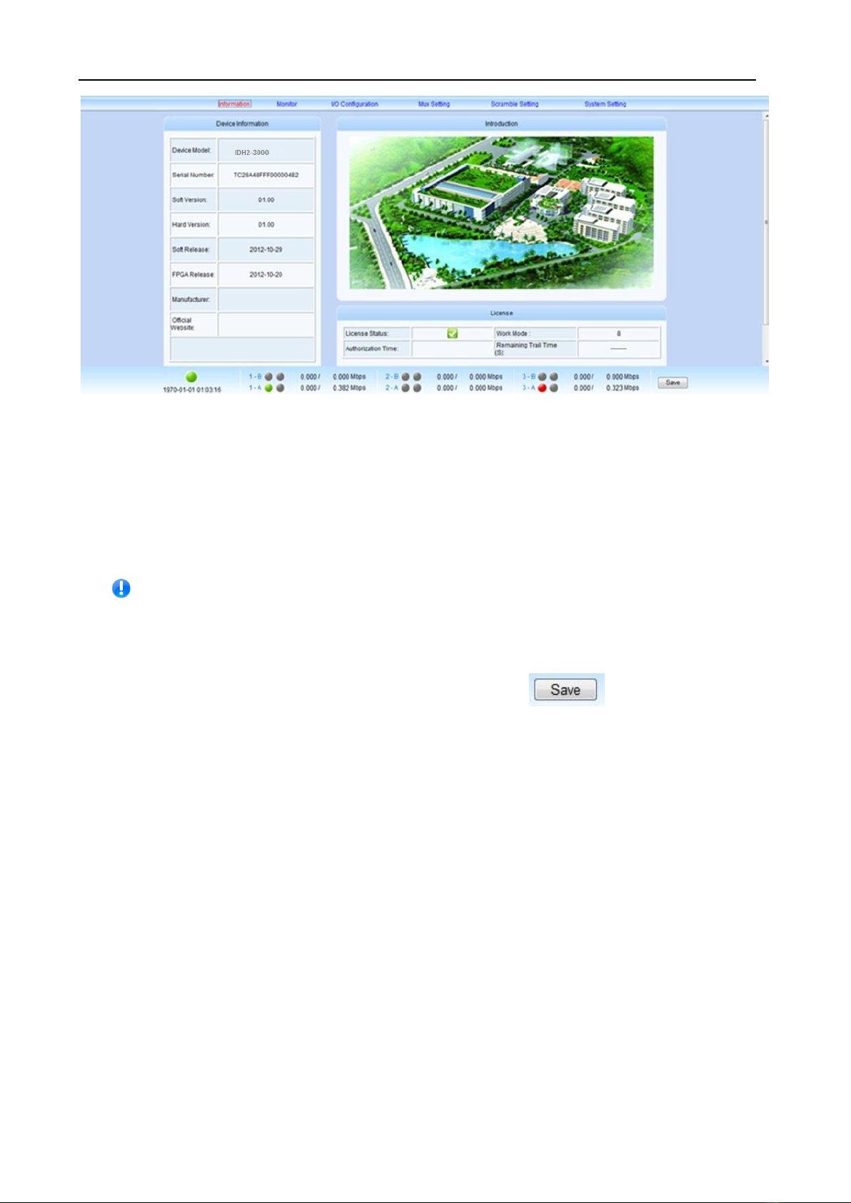
-11-
Fig.5 Default Page
In the default page, there are the information of device (model, serial number, etc), authorization state,
and some important specifications will be refreshed in real time. You could enter into the “device
monitoring”, “input & output”, “program multiplexing”, “program scrambling”, “device setting” page by
clicking different hyperlinks in the area of main-menu across the top of this page.
【Remark】: Device will not auto-save your parameters. If the device restarts, the
parameters will change to the state, which you saved last time. If you have never
saved your parameters, all the parameters will change to the default state. So if you
want to save your own parameters, please click in lower right corner
after you finish setting IDH2-3000 Series.

-12-
§
§3
3.
.2
2.
.2
2
U
Us
se
er
r
M
Ma
an
na
ag
ge
em
me
en
nt
t
We recommend you to change the user and password after logging by the default user and password for
the safety. You can edit your user information in the user management page.
Click “device setting” in the home page, and then you have the device setting page, as shown in the
figure below:
Fig.6 Device setting page
Click “user management” in the “select option” area on the left side of this page, and
then you have the user management page, as shown in the figure below:
Fig.7 User management page
In this page, you could add new user, edit old users’ information or delete an user.
【Remark】: Only “admin” user could enter into the user management page.
§
§3
3.
.2
2.
.2
2.
.1
1
Add new user

-13-
In the “Add New User” column of “User Management” page, please input correctly users’ user and
password, and then confirm the password.
After finishing these steps, click “submit” to add a new user. If you add successfully a new user, there will
show your user information on the right side, as shown in the figure below:
Fig.8 New User Information
【Remark】: All new users are normal users. They are only permitted to set different parameters, but
they don’t have the right to manage the other user or upgrade the system.
§
§3
3.
.2
2.
.2
2.
.2
2
Edit users’ information
In the user information list in this page, you can edit an user by clicking the modification button in the
same row.
That makes you edit your password, as shown in the figure below:
Fig.9 Edit users information
In this bar, you can edit your user’s password and that will be accomplished by clicking “submit”.
【Remark】: You could not delete the “admin” user, but you can change the password of this user.
When you use IDH2-3000 Series for the first time, you should change admin’s password at first and then
save this password.
-14-
§
§3
3.
.2
2.
.2
2.
.3
3
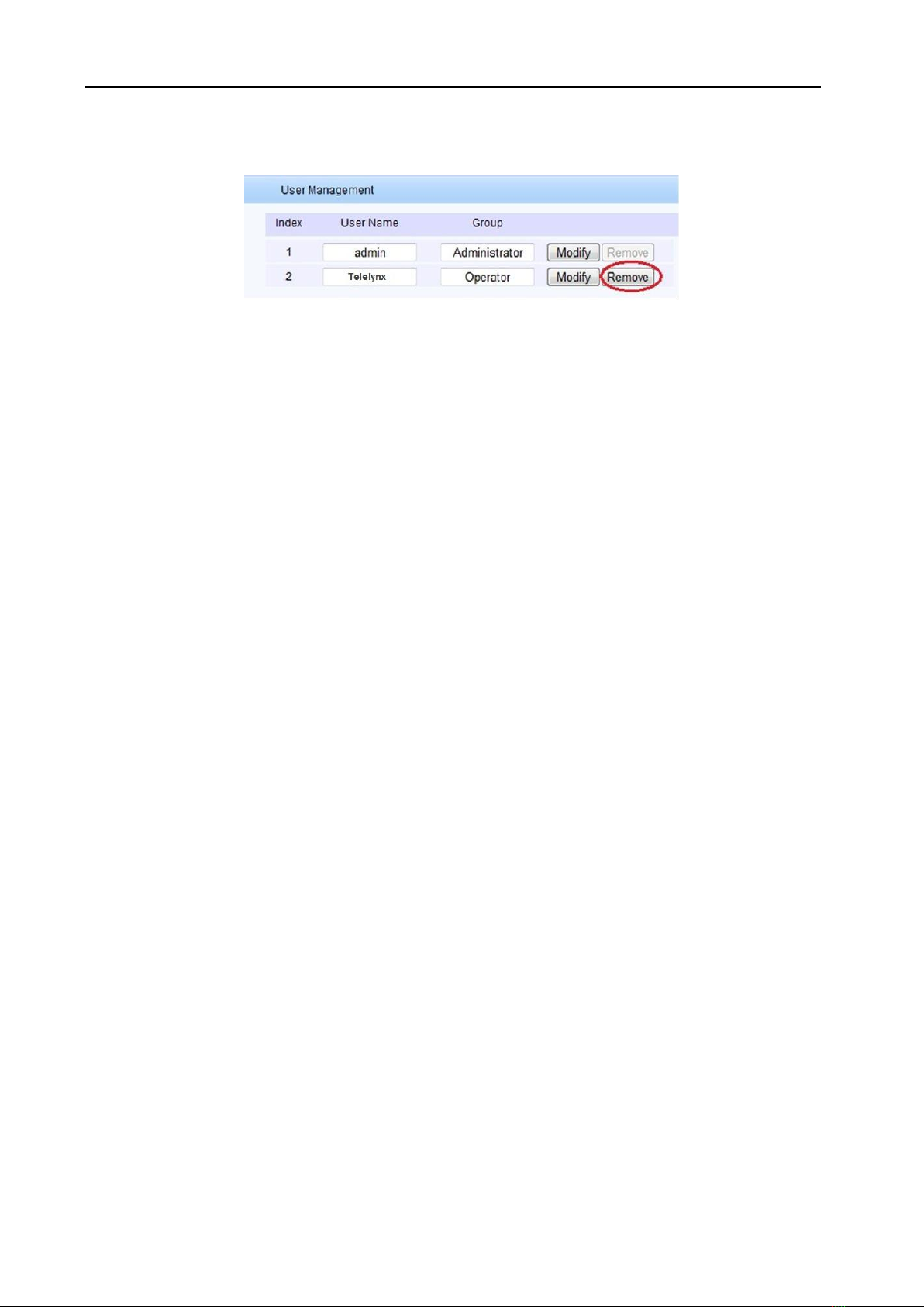
Delete an user
In the user information list in this page, click the “delete” button in the same row to delete this user.
【Remark】: You will not permit to delete admin user but can delete the normal user.
-15-
§
§3
3.
.2
2.
.3
3
B
Ba
as
si
ic
c
p
pa
ar
ra
am
me
et
te
er
r
s
se
et
tt
ti
in
ng
g
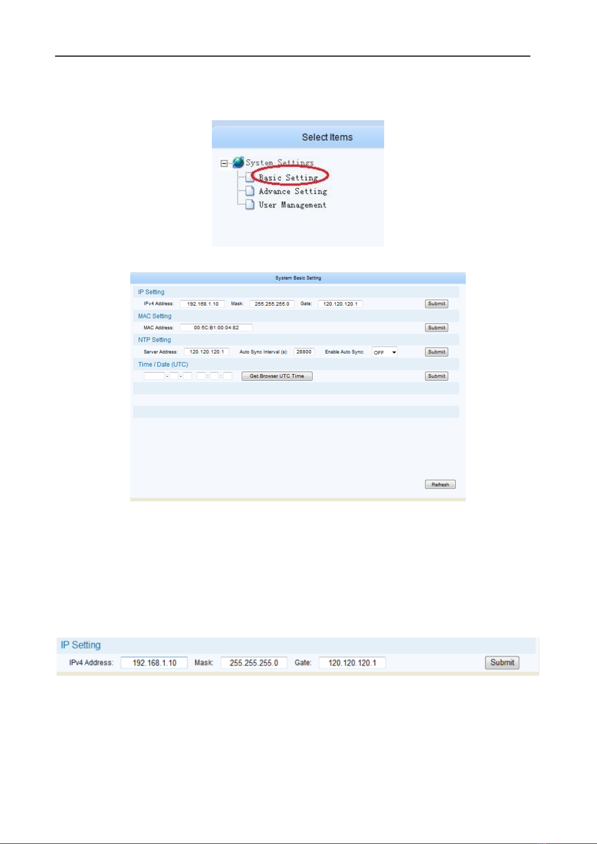
In the system setting page, click “basic setting” in the “select option” area
To enter basic parameter setting page, as shown in the figure below:
Fig.10 Basic Parameter Setting Page
In this page, you could accomplish the setting of IP address, MAC address, set the IP address of time
synchronization server, open or close this service, and set the UTC time synchronization, etc.
§
§3
3.
.2
2.
.3
3.
.1
1
I
IP
P
S
Se
et
tt
ti
in
ng
gs
s
In the page of figure 11, input a right IP address in the “IP settings” bar, then click “submit” to set
IDH2-3000 Series’ network parameter.
【Remark】: To ensure the proper working of device, you should guarantee that the management port IP
address and IDH2-3000 Series’ management server IP are in the same network segment
-16-
§
§3
3.
.2
2.
.3
3.
.2
2
M
MA
AC
C
a
ad
dd
dr
re
es
ss
s
s
se
et
tt
ti
in
ng
g
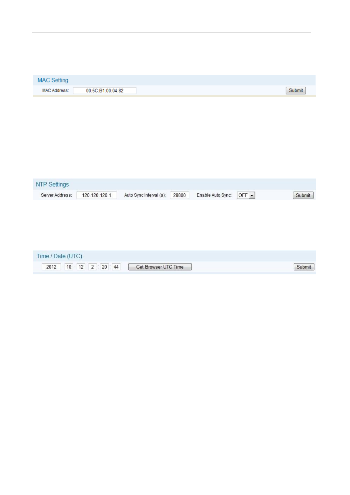
In the page of figure 11, input a right MAC address in the “MAC settings” bar, then click “submit” to set
IDH2-3000 Series’ MAC address.
【Remark】: Our products have the first 3 bytes “00:5C:B1” in the MAC address, that couldn’t be
modified.
§
§3
3.
.2
2.
.3
3.
.3
3
P
Pa
ar
ra
am
me
et
te
er
r
s
se
et
tt
ti
in
ng
g
a
ab
bo
ou
ut
t
s
sy
ys
st
te
em
m
c
cl
lo
oc
ck
k
Set time synchronization server: In the page of figure 11, you can set IP address of network clock
server, auto synchronization time lag, auto synchronization switch in the “time synchronization protocol”
bar.
【Remark】: When you set a right network clock server address, IDH2-3000 Series will update his
system clock with the period which the user sets if SNTP service and network clock server are enabled.
Set system clock by manual operation: In the page of figure 11, you can set manually the system
clock in the “date/time(UTC)” bar. And you can also click ”get UTC time”, then click ”submit” button to
finish setting.
【Remark】:
1. If the network clock server address has already configured and enabled, and the SNTP server works
properly, the device will get the system clock from the network clock server, at this time, the manually
configured clock will be invalid.
2. Select the synchro-browser UTC clock to be the standard UTC(0zone) clock, and this clock may be
different from the clock shown on server, e.g. if the server clock is UTC+8:00, the final clock will be
differ about 8 hours.
-17-
§
§3
3.
.2
2.
.4
4
A
Ad
dv
va
an
nc
ce
ed
d
P
Pa
ar
ra
am
me
et
te
er
r
s
se
et
tt
ti
in
ng
g
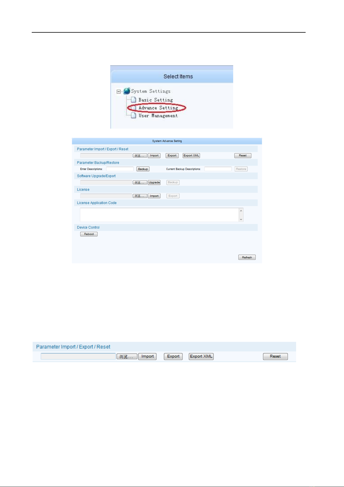
In the “system setting” page, click “Advanced setting” in the “select option” area
To enter the parameter setting page, as shown in the figure below:
Fig.11 Advanced setting page
In this page, you could import/export/reset the parameters, back-up/recover the parameters,
upgrade/back-up the software, import the authorization document, restart the device,etc.
§
§3
3.
.2
2.
.4
4.
.1
1
I
Im
mp
po
or
rt
t/
/E
Ex
xp
po
or
rt
t/
/R
Re
es
se
et
t
t
th
he
e
p
pa
ar
ra
am
me
et
te
er
rs
s
Import the parameters: In the page of figure 13, click “browse” button in the “Import/Export/Reset the
parameters” bar to choose the parameters’ document of the device.
Fig.12 Import/export/reset the parameters page
After choosing the parameters’ document, click “Open” button. Then return to last page, click “Import”
button, system will change the page to uploading management page, as shown in the figure below:

-18-
Fig.13 document uploading management page
System will checkout the uploading document, if its format is right, there will appear mark in the
“uploading” bar and “document checkout” bar. Click “Submit” button, you’ll have this dialog box:
Click “YES” button to import the parameters.
【Remark】:
1. Please do not turn off the device or pull the power off when the device is importing the parameters.
2. The device will restart after importing the parameters.
3.
Export the parameters: In the page of figure 13, click “Export” button, it allows you to save parameter to
a file. then click “Save” button to choose the path you wanted to save these parameters.
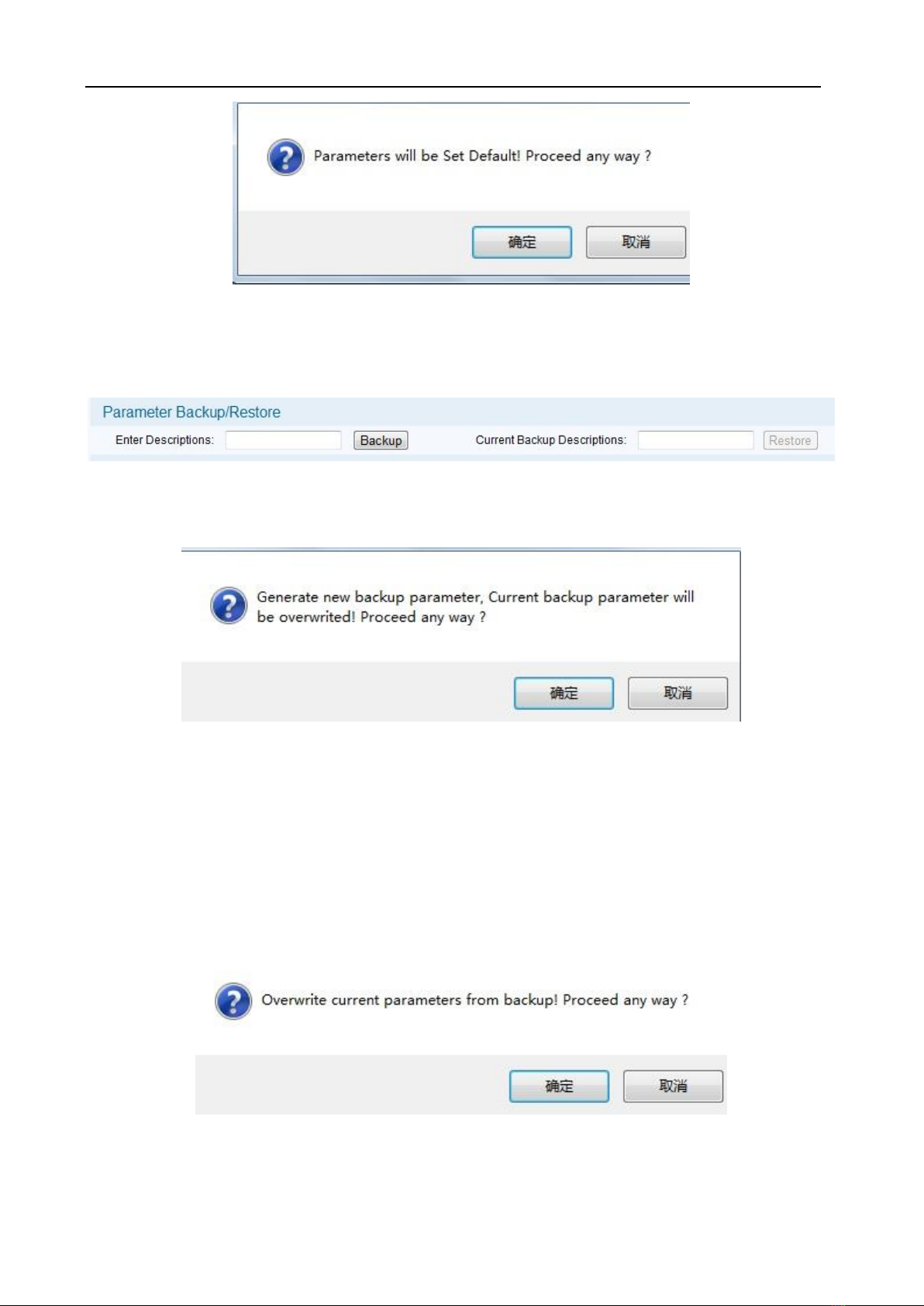
Reset the parameters: In the page of figure 13, click “Reset” button, then you’ll have this dialog box:
-19-
§
§3
3.
.2
2.
.4
4.
.2
2
B
Ba
ac
ck
ku
up
p/
/R
Re
es
st
to
or
re
e
t
th
he
e
p
pa
ar
ra
am
me
et
te
er
rs
s
Back-up the parameters: In the page of figure 15, there is a “parameter Backup/Restore” bar:
Fig.14 “parameter back-up/recover” bar
Fill in the “input parameter description information” (just like 2012-08-22), click “Backup” button, you’ll
have this dialog box:
Click ”YES” button, system will create a new back-up document. In the same time, “input parameter
description information” will show you the new back-up document’ description, as shown in the figure
below:
【Remark】: System could only save a unique back-up document each time, the new back-up document
will cover the last one.
Restore the parameters: When the device has a back-up document, click “Restore” button, you’ll have
this dialog box:
Click “YES” button to import the parameters.
-20-
§
§3
3.
.2
2.
.4
4.
.3
3
U
Up
pg
gr
ra
ad
de
e/
/E
Ex
xp
po
or
rt
t
t
th
he
e
s
so
of
ft
tw
wa
ar
re
e
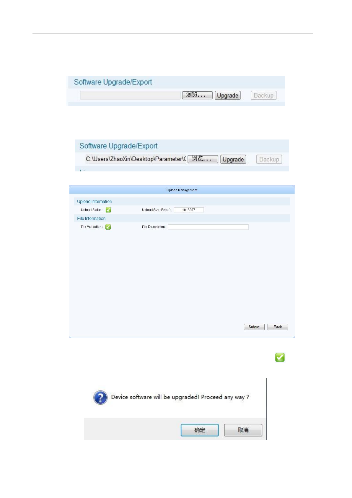
As shown in the figur12, you can choose the upgrade document in the “Software Upgrade/Export” bar,
then import it to upgrade the device.
Click “Browse” button, you’ll have this dialog box:
Select the upgrade document, click “Open” button, as shown below:
Click “Upgrade” button, system will change the page to uploading management page, as shown below:
Fig.15 Document uploading management page
System will checkout the uploading document, if its format is right, there will appear mark in the
“uploading” bar and “document checkout” bar. Click “Submit” button, you’ll have this dialog box:
Click “YES” button to upgrade the device.
Table of contents


