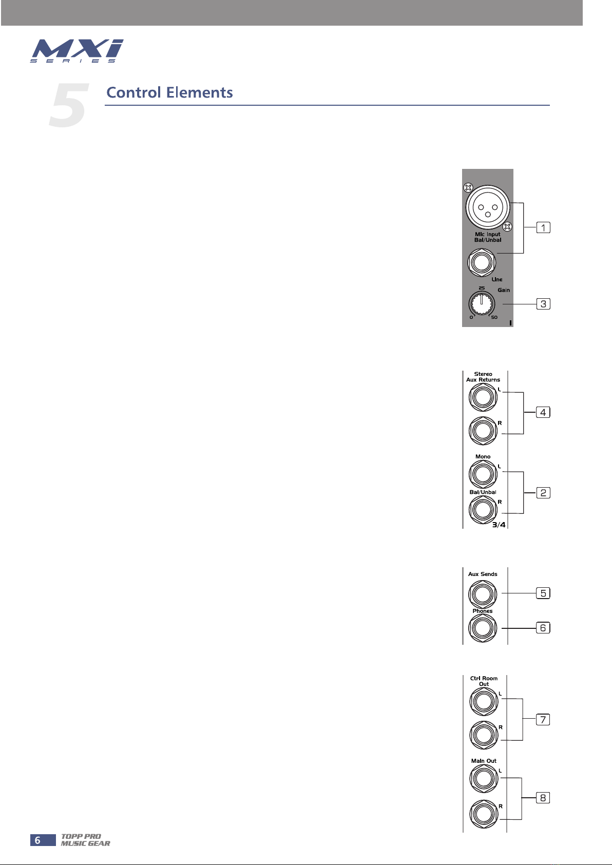
Topp Music Gear MXI Series User manual

MXi.6FX


This device complies with Part 15 of the FCC Rules. Operation is subject to the following two
conditions: (1) this device may not cause harmful interference, and (2) this device must accept
any interference received, including interference that may cause undesired operation.
FCC Statement:
"This equipment has been tested and found to comply with the limits for a Class B digital device,
pursuant to part 15 of the FCC Rules. These limits are designed to provide reasonable protection
against harmful interference in a residential installation. This equipment generates, uses and can
radiate radio frequency energy and, if not installed and used in accordance with the instructions,
may cause harmful interference to radio communications. However, there is no guarantee that
interference will not occur in a particular installation. If this equipment does cause harmful
interference to radio or television reception, which can be determined by turning the equipment
off and on, the user is encouraged to try to correct the interference by one or more of the
following measures:
—Reorient or relocate the receiving antenna.
—Increase the separation between the equipment and receiver.
—Connect the equipment into an outlet on a circuit different from that to which the receiver is
connected.
—Consult the dealer or an experienced radio/TV technician for help."

Thank you for purchasing the 6-channel mixing console with 24-bit digital multi-effect.
MXi6.FX mixing console is a remarkable compact mixing desk that does not find many equals in
the market today. With 2 microphone and 2 stereo Line-level inputs for small live performances,
small studio recording and general PA applications, MXi6.FX also includes a 24-Bit digital
multi-effect with 16 Factory Presets and separate level for digital reverb. There is a 3- band EQ on
all input channels and separate Main Mix and Control Room outputs for operation with different
volume settings. Use it for small GIGs and RECORDING. MXi6.FX also is a flexible tool for
Multimedia presentations.
Thank you again for making right choice in purchasing the TOPP PRO MUSIC GEAR.
• 2 MIC input channels with gold plated XLR and balanced LINE input
• 2 stereo input channels with balanced TRS jacks
• Ultra-low noise discrete MIC pre-amps with +48V Phantom power
• Extremely high headroom offering extra dynamic range
• Balanced inputs for optimal signal integrity
• Warm, natural 3-band EQ on each channel
• Built-in 24 bits digital effects processor
• Peak LED on each channel
• AUX send for internal effects or stage monitoring
• Main output, Control room and headphone outputs
• 2-Track inputs assignable to main mix, control room/headphone outputs
• Highly accurate 4-segment bar graph meters

Hookup Diagram

FRONT PANEL
1- MIC INPUT
MXi.6FX is equipped with 2 low-noise microphone preamplifiers with optional
phantom power, 50 dB of Gain and 115 dB of S/N ratio. You can connect almost
any type of microphone. Dynamic microphones do not need phantom power. Use
phantom power only with condenser microphones but make sure that the
phantom power button is disengaged before connecting the microphone.
Phantom power will not damage dynamic microphones but it may damage tube or
ribbon microphones so make sure to read the microphone instructions manual
before engaging phantom power. Use switch (24) to activate/deactivate phantom
power. These two channels are also equipped with 1/4" TRS balanced/unbalanced
LINE-IN plugs to connect line-level instruments such as keyboards, drum machines
and effect devices.
NOTE: Never try to connect a line-level signal to the XLR MIC input when the
phantom power is engaged or you may seriously damage your equipment.
2- STEREO LINE INPUTS
These are channels 3/4, and 5/6. They are organised in stereo pair and provided
with 1/4" TRS phone sockets. If you connect only the left jack, the input will operate
in mono mode, that's mono signal will appear on both input channels. You can use
these inputs with a stereo keyboard, drum machine, etc.
3- TRIM
This control is provided with 2 different indication rings: one is for the MIC and the
other for the LINE input. When you use a Microphone, you shall read the MIC ring
(0~50 dB); when you use a line level instrument, you shall read the LINE ring
(+15~-30dB). For optimum operation, you shall set this control in a way that the
PEAK LED will light up only occasionally in order to avoid distortion on the input
channel.
4- STEREO AUX RETURNS
You can use these stereo 1/4" phone sockets to return the stereo signal of an effect
unit to the Main Mix. Alternatively you can use them as an extra auxiliary input and
using the AUX RETURN level control as volume control. The signal will be sent
directly to MAIN MIX control.
5- AUX SEND
This 1/4" phone socket is used to send out the signal from AUX bus of the input
channels into external devices such as effect units and/or stage monitors. AUX
SEND is wired post-fader to control the signal of the internal multi-effects unit. You
can also connect an external effect unit. In such case, the internal effect unit will
be automatically disconnected. If you want to wire the AUX circuit as pre-fader,
read Chapter 6. of this Manual. In the pre-fader mode, the AUX bus can send the
signal to a stage monitor.
6- PHONES
This socket will be used to send the signal to a pair of headphones.
7- CTRL ROOM OUTPUT
These 1/4" phone sockets will be used to send the signal to a pair of powered
Studio Monitor speakers or to a second set of PA.
8- MAIN MIX OUTPUTS
This stereo output is controlled by the Main Mix Level on Master section and will
send the audio signal to an amplifier or to a pair of active speakers. The output
level can be varied from -∞ to +15 dB.

9- TAPE IN
Use the Tape input to connect a CD Player, Tape, DAT, iPOD or any other line-level
source. You can send this signal either to CONTROL ROOM OUTPUT and/or to the
MAIN MIX OUTPUT using the relative 2TK TO select buttons.
10- TAPE OUT
These RCA jacks will route the main mix signal into a tape or DAT recorder.
CHANNEL STRIP
3-BAND EQ
You have three EQ control for each mono and stereo input channel each
providing +/-15 dB of boost and cut (MID is +/-12 dB). The signal will be
unaffected when the controls are on center position.
You may use an external equalizer to make up a mix properly but a master
equalizer will not have effect on a single channel and you may overload the
signal easily. Individual EQ will give you a much better control on single tracks.
11- HI
If you turn this control up, you will boost all the frequencies above 12 kHz
(shelving filter). You will add transparency to vocals & guitar and also make
cymbals crispier. Turn the control down to cut all frequencies above 12 kHz. In
such way, you can reduce sibilances of human voice or reduce the hiss of a Tape
player.
12- MID
This is a peaking filter and it will boost/cuts frequencies with their center at 2.5
kHz. This control will affect especially upper male and lower female vocal ranges
and also the harmonics of most musical instruments.
13- LOW
If you turn this control up, you will boost all frequencies below 80 Hz. You will give more punch to bass
drums and bass guitar; and you will make the male vocalist more "macho". Turn it down and you will cut all
the frequencies below 80 Hz. In this way you can avoid low-frequency vibrations and resonance thus
preserving the life of your woofers.
14- AUX SEND
This control is used to adjust the level of the signal sent to AUX SENDS output (if nothing is connected to
AUX SEND socket, the signal will be sent to the resident digital multi-effect), and such adjustment doesn't
affect the main mix output signal at all. AUX is configured as POST fader, however, it can also be configured
as PRE fader through internal modification. (For more detail, please refer to chapter 6)
15- PAN/BAL
This is the PANORAMA control, or balance control. You can adjust the stereo image of the signal via this
control. Keep this control in center position and your signal will be positioned in middle of stage. Turn this
control fully counter clockwise and the signal will be present only on the left speaker and vice-versa. Of
course a large number of intermediate positions is available.
16- PEAK LED
This red LED will let you know about the status of the signals processed into MXi.6FX . Connect a
microphone or an instrument to MXi.6FX and sing/play at normal volume. Set the level control of that
channel so that the PEAK LED lights-up only occasionally. If this LED is always on, you are experiencing a lot
of distortion and you should turn the TRIM control down or reduce the EQ boosting. If this led never lights
up, turn the TRIM control up again.
17- LEVEL
This knob controls the channel's level from -∞ to +15 dB.

MASTER SECTION
18- MAIN MIX LEVEL
This knob controls the level of the signal sent to MAIN OUTPUTS and TAPE OUT. Also AUX RETURNS signals
will be sent to this control.
19- PHONES/CONTROL ROOM LEVEL
This knob controls the signal sent to CONTROL ROOM OUTPUT & PHONESOUTPUT.
20- OUTPUT LEVEL METERS
These consist of two column of 4 LEDs each ranging from -20 dB to OL (CLIP). The 0 LED corresponds to a
level output of 0 dBu. The CLIP LEDs come to life when the output reaches OL. Set the MAIN MIX level
control so that the CLIP LEDs only flashes occasionally. In general, you get a good mix level when the Meter
LEDs operate in the range 0 to +10. If you exceed +10, you will get distortion. If even -20 LEDs are sleeping
your signal-to-noise ratio will suffer.
21- AUX RETURNS (DFX)
This knob controls the level of effects received from the
STEREO AUX RETURN sockets. Such signals will be routed
directly into the MAIN MIX. If you have no need to connect an
external multi-effect, you can use AUX RETURN inputs as
additional instrument inputs &use this as Volume control.
22- 2TK TO CTRL ROOM
If you push down the 2TK TO CONTROL ROOM button, the 2
TRACK IN signal will be routed into the Control Room output
and the level will be adjusted by the Control Room knob
nearby the Main MIX LEVEL knob.
23- 2TK TO MIX
If you push down the 2TK TO MIX button, the 2 TRACK IN signal will be routed into the MAIN output and
will be adjusted by the MAIN MIX LEVEL knob.
24- PHANTOM PWR Switch
This button will apply +48 Volt Phantom Power only to the 2 XLR MIC input sockets. When condenser
microphones are not used, please make sure that the Phantom Power is disengaged.
25- PHANTOM LED
This LED indicates when the PHANTOM POWER is engaged.
26- POWER LED
This LED indicates when your MXi.6FX is switched-on.
DSP SECTION
Your MXi.6FX includes a quite unique and innovative digital multi-effects with 24-bit resolution and high
dynamic range. Unlike other multi-effects where all the presets are available in a sequence and vice a single
control, MXi.6FX multi-effect unit is organized with a 16 presets control and relative Level control for
vibrato and modulation controls such as chorus and flanger. You can add reverb at any time with a separate
Level control or you can just use the reverb keeping the FX level control turned down.
27- DISPLAY
It displays the selected preset.
28- PRESET SELECTOR
Adjust this knob to select the right effect you wish to perform.
There are totally 100 options for you: ECHO, VOCAL, PLATE
andversatile two-effect combination. When you are satisfied with
the right preset, push this knob to store this preset you want.

29- PEAK/MUTE LED
This LED lights up when the input signal is too strong or in case of the digital effect module being muted.
30- MUTE SWITCH
This switch is used to activate/deactivate the effect facility.
REAR PANEL
31- AC INPUT
This connector is used to connect the supplied AC Adapter.
32- POWER SWITCH
This switch is used to turn the main power ON and OFF.
1- Speakers should be placed in a position that allows for unobstructed sound projection. In
many instances is beneficial for speakers to be elevated on tripod stands to achieve maximum
dispersion and reach.
2- Use professional advice or service when hanging and installing speakers. Please take
precautions to secure them to prevent them from falling and hurting someone. Care should be
taken as to not damage the cabinet or its components. Please comply with all pertinent
Regulations.
3- Use quality cables. Using quality cables will ensure the best possible sound.
4- For best results match the speakers to a good amplifier that matches the wattage and
impedance of your speakers. Proper amplification power results in good quality audio and
longer component life. Check out the power requirement for your cabinet.
5- Avoid pointing a microphone directly at an amplified speaker doing so, could cause feedback
possibly damaging speaker components and your hearing.
Installation Tips
Enjoy the sound!

Wire Connections

Block Diagram

Preset List

MXi.6FX MIXING CONSOLE
Technical Specification


Other manuals for MXI Series
1
This manual suits for next models
1
Table of contents
Other Topp Music Gear Music Mixer manuals

Topp Music Gear
Topp Music Gear TPM4200FX MKII V2 User manual

Topp Music Gear
Topp Music Gear MX.5 V2 User manual

Topp Music Gear
Topp Music Gear MX1642 User manual

Topp Music Gear
Topp Music Gear MXi.5 User manual

Topp Music Gear
Topp Music Gear Mx2442 User manual

Topp Music Gear
Topp Music Gear DMX24.4 User manual

Topp Music Gear
Topp Music Gear TPM 4250 MKII User manual

Topp Music Gear
Topp Music Gear TPM8.2000 User manual

Topp Music Gear
Topp Music Gear MXi.1222CFX User manual

Topp Music Gear
Topp Music Gear MX.22/2FX User manual