Telemetrics PT-HP-S4 User manual
Operation Manual
HP Servo P/T Head (48V)
Model PT-HP-S4
92 56156 000
P/N 92 56156 000-11 Rev. A
6 Leighton Place
Mahwah, New Jersey 07430
www.telemetricsinc.com

Table of Contents
1.0 Scope..................................................................................................................... 1
2.0 Introduction ............................................................................................................1
3.0 Specifications......................................................................................................... 2
4.0 System Cables....................................................................................................... 3
4.1 Power Cable...................................................................................................................................................3
4.2 Serial Data Connection..................................................................................................................................3
4.3 Auxiliary Connections...................................................................................................................................4
5.0 Camera Power & Camera Control.......................................................................... 4
6.0 Lens Interface Information...................................................................................... 8
7.0 Connector Input/Output Signals .............................................................................9
8.0 PC Boards............................................................................................................ 13
APPENDIX A Telemetrics Serial Data Protocol.............................................................15
APPENDIX B Controller Board 53915 DIP Switch Setting............................................ 28

List of Figures
Figure 1. Pan/Tilt Head..................................................................................................1
Figure 2 Power Cable CA-PWR-7XLR- XXX ................................................................3
Figure 3 Serial Data Cable...........................................................................................3
Figure 4. Trolley/Televator Cable CA-S2-AUX.............................................................4
Figure 5 Sony DXC-950/990 Power Cable ...................................................................5
Figure 6 Sony DXC-950/990 Data Cable ......................................................................5
Figure 7 Sony DXC-950/990 Power/Data Cable...........................................................6
Figure 8. Panasonic AW-E600/800 Power Cable ........................................................6
Figure 9. Panasonic AW-E600/800 Data Cable ...........................................................6
Figure 10. Panasonic AW-E600/800 Power/Data Cable..............................................7
Figure 12. Hitachi HV-D15 Power/Data Cable .............................................................7
Figure 13. Hitachi Z-3000W Power Cable....................................................................8
Figure 14. Hitachi Z-3000W Power/Data Cable ...........................................................8

LITHIUM BATTERY CAUTION, Danger of explosion if the internal lithium battery
is replaced incorrectly. Replace only with the same or equivalent type
recommended by the manufacturer. Dispose of used batteries according to the
battery manufacturer’s instructions.
The Lightning Flash With Arrowhead symbol, within an equilateral triangle,
alerts the user to the presence of uninsulated dangerous voltage within the
product’s enclosure that may be of sufficient magnitude to constitute a risk of
electric shock.
The Exclamation Point symbol, within an equilateral triangle, alerts the user to
the presence of important operating and maintenance (servicing) instructions in
product literature and instruction manuals.

1
1.0 Scope
This manual contains information for the Telemetrics HP Servo Pan/Tilt Head Model
PT-HP-S4, Part No. 92 56156 000. This Pan/Tilt is designed for use with ENG and
smaller type cameras. Due to the different types of cameras and lenses the
Pan/Tilt interfaces with, many options are manufactured. Some of those options
are described in the following paragraphs. Please consult the factory for the
specific options available.
2.0 Introduction
The PT-HP-S4 is a robotic camera pan/tilt head with smooth variable operating
speed. Heavy duty cross roller bearings and swings motors with isolation mounts
provide quiet operation. The lens connector provides direct connection and
interface to lens functions. Lens interface options are also available. The Pan/Tilt
head is powered from the Rack Mount Power Supply PS-RM-48 and converts the
48V to appropriate voltage levels for the head, auxiliary robotics devices, camera,
lens and viewfinder.
The unit is controlled through serial data interface using RS-232 standard or RS-
422 optional or 10/100 BASE-T Ethernet connections. Manual smooth motion is
accomplished using velocity servo controls. Two hundred and fifty five (255)
presets are available. Presets are called using shot convergence technology,
allowing for smooth motion like presets. An optional camera control feature is
available for certain cameras. It has Tally LED on front panel to indicate camera
“On Air”.
The PT-HP-S4 is typically controlled by a Telemetrics Rack Serial Control Panel
(CP-R-3A or CP-R-2A), Desktop Serial Control Panel (CP-D-3A or CP-D-2A) or
Remote Control Panel (RCP). Second party RS-232/422 control systems can also
be used to interface with the unit. Please consult factory for configuration
assistance. See Appendix A for Serial Protocol specifications.
Figure 1. Pan/Tilt Head
6"
Ethernet
DC POWER ETHERNET
CAMERA LENS AUX SERIAL
12.505"
7" 10"
Power
Lens Serial
Cam Ctl Aux

2
3.0 Specifications
Input voltage 38-53VDC
Input current 6.8 A max
Input Power 50 W
(P/T head only)
Input Power Conn. 7-pin Male XLR
Camera Power 40 W (13.5 VDC, 3 A max)
Pan travel ±170° w/endstops, ±200° w/o endstops
Tilt travel ±35° (+35°, -90° PTO-HP-S4-EA)
*End stops Resolution Continuous Angular Adjustable – Abrupt Stop
Electronic: Smooth Stop
*Min/Max pan velocity 0.01° - 25°/sec (40°/sec High Speed PTO-HP-S4-HS)
*Min/Max tilt velocity 0.01° - 25°/sec (40°/sec High Speed PTO-HP-S4-HS)
Stopping Accuracy ±5 arc min/0.08°
Audible Noise 37 dB(A) max, IEC Free Field
Operating Modes 32 bit velocity and positional servo control
Preset position with multi-axis convergence
Mounting Upright or inverted
Dynamic Load 35 lbs. max. (16 kg)
Weight 14 lbs. (6.3 kg)
Dimensions 10” H x 11 ¼” W x 6” D
18”H x 11 ¼” W x 6” D (Extended Yoke)
14 ½”H x 11 ¼” W x 6” D (Extended Arms)
* End stops are set to ±170° Pan and ±35° Tilt unless otherwise specified by customer.

3
4.0 System Cables
4.1 Power Cable
Power to the unit is made via interconnect cable CA-PWR-7XLR-XXX to the
7-pin XLR power connector located on the rear of the unit (Note: XXX=Feet).
The other end of interconnect cable connects to the external power supply.
Figure 2 Power Cable CA-PWR-7XLR- XXX
4.2 Serial Data Connection
Communication to the unit is made via serial data cable CA-RS to the 9 pin
serial data connector located on the rear of the unit. The other end of the
cable connects to the control panel. Units configured for RS-232 can have a
maximum distance of 100 feet between the unit and the control panel. Units
configured for RS-422 can have a maximum distance of 4000 feet between the
unit and the control panel. (Note: Units are set to accept either RS-232 or RS-
422 at the factory. See Table 1 for proper DIP switch settings.)
Figure 3 Serial Data Cable
LENGTH: VARIABLE (CUT CABLE XXX' +5")
RTN
GREENGREEN6
1
3
2
4
5
7
J1
NEUTRIK - NC7MX
CONN 7-PIN XLR MALE
LENGTH
STRIP
SHIELD
SLEEVING
LABEL
1/2"
LABEL
SUPPLY
TO PWR
QUABBIN #4177
BROWN
WHITE
BLUE
BLACK
RED
ALPHA #25836
BLUE
ORANGE
WHITE
RED
BLACK
+48V
RTN
RTN
+48V
+48V 2
6
5
4
3
1
7
J2
NEUTRIK - NC7FX
CONN 7-PIN XLR FEMALE
STRIP
LENGTH
1/2"
SLEEVING
SHIELD
TO P/T
4
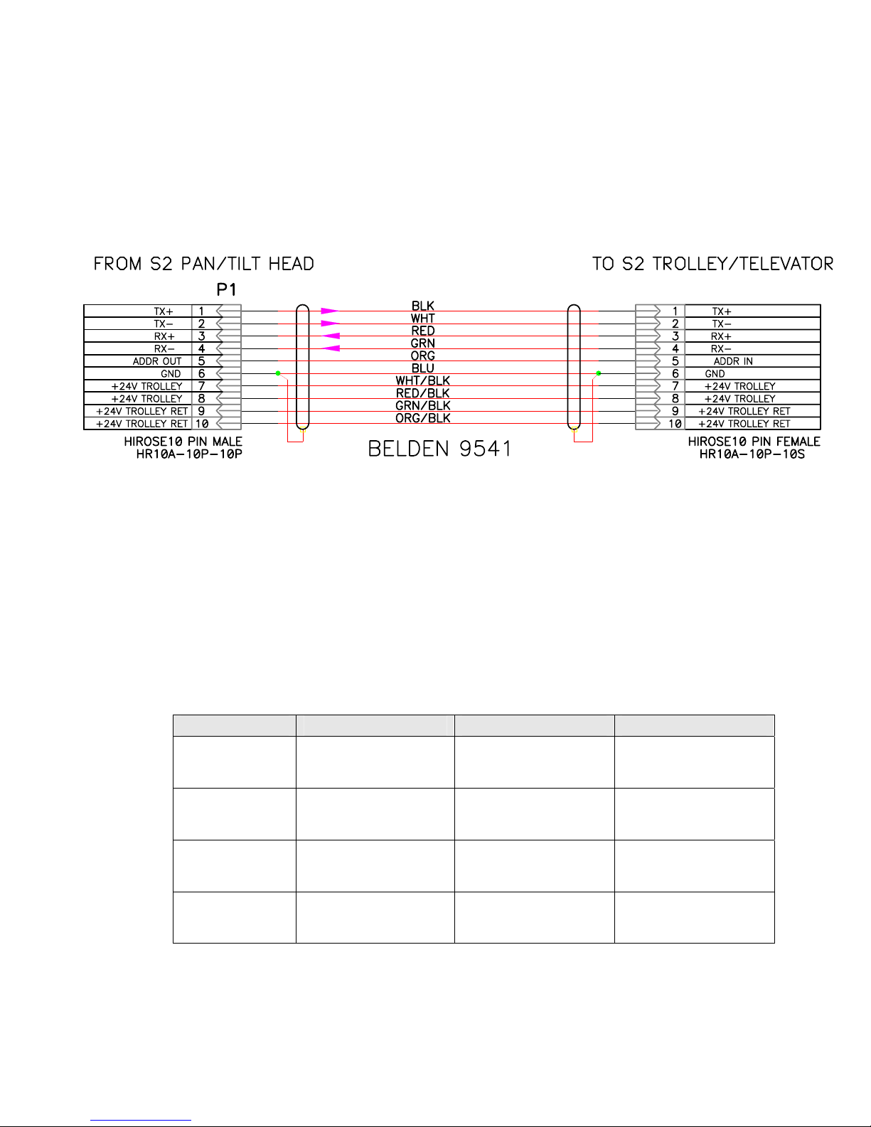
4.3Auxiliary Connections
Power and control of the Telemetrics Trolley and Televator units is
accomplished using the auxiliary connector on the pan/tilt. It is important to
remove power from the pan/tilt prior to connecting or disconnecting the
auxiliary cable. Damage may occur if the unit is powered when connecting or
disconnecting the cable. Note: Refer to Appendix for information on Aux Axis
Soft Limit configuration.
Figure 4. Trolley/Televator Cable CA-S2-AUX
5.0 Camera Power & Camera Control
Telemetrics pan/tilt systems are capable of providing power and data to virtually all
manufacturers’ cameras. A Telemetrics power supply that includes a 15V module
for the camera must be used when camera power is required. In addition, the
Telemetrics control panel must be configured to accept the camera ROP to provide
camera control. See Table 3 for currently available accessory cables.
Table 1 Camera Power and Data Cables
Camera Power Data Power/Data
Sony
DXC-950/990 CA-S2-P-DXC990 CA-S2-D-DXC990 CA-S2-PD-DXC99
Panasonic
AW-E600/800 CA-S2-P-E600 CA-S2-D-E600 *CA-S2-PD-E600
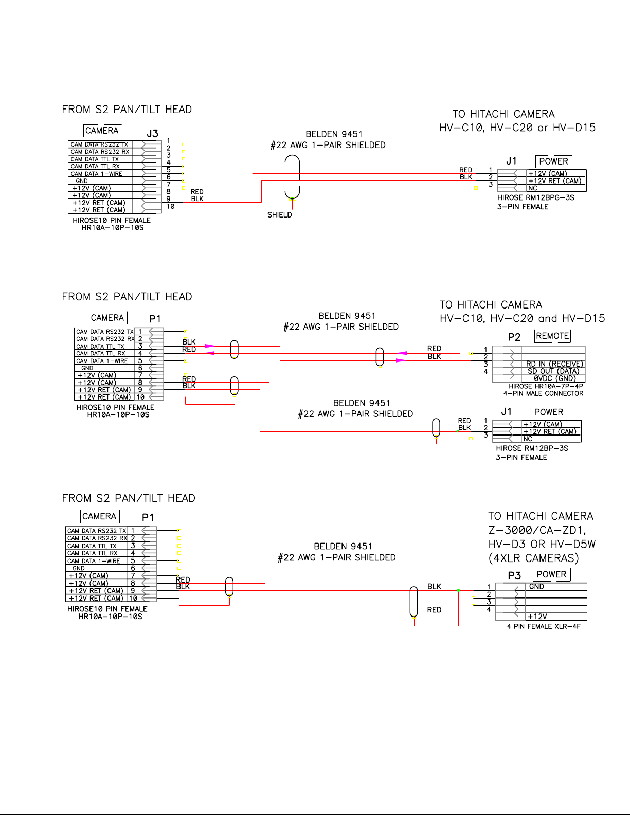
Hitachi
HV-D15 CA-S2-P-HVD15 CA-S2-PD-HVD15
Hitachi
Z-3000W CA-S2-XLR-4F CA-S2-PD-Z3000
*Note: The Panasonic Camera Control Cable requires removal of the screw
terminals on the 50 Pin connector.
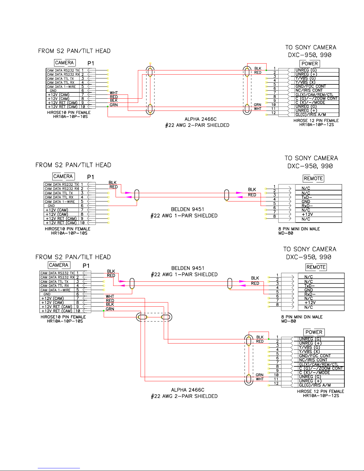
5
Figure 5 Sony DXC-950/990 Power Cable
Figure 6 Sony DXC-950/990 Data Cable
6
Figure 7 Sony DXC-950/990 Power/Data Cable
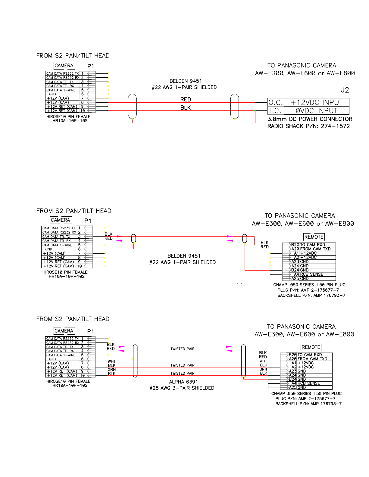
Figure 8. Panasonic AW-E600/800 Power Cable
Figure 9. Panasonic AW-E600/800 Data Cable
7
Figure 10. Panasonic AW-E600/800 Power/Data Cable
Figure 11. Hitachi HV-D15 Power Cable
Figure 12. Hitachi HV-D15 Power/Data Cable

8
Figure 13. Hitachi Z-3000W Power Cable
Figure 14. Hitachi Z-3000W Power/Data Cable
6.0 Lens Interface Information
1. In order to use Fujinon BMD or Canon KTS series teleconferencing lenses
with the Pan/Tilt, simply plug lens controls pendant into the Pan/Tilt lens
connector. NOTE
If the controller is a Telemetrics preset system, additional modifications
must be performed to bring the focus and zoom positional voltages out of
the lens. Please refer to preset controller manual for complete instructions.
2. If the zoom lens is not a teleconference style lens (a teleconference lens
has an integral zoom and focus amplifier), an interface cable will be
supplied. The connector marked “zoom” plugs into the zoom servo and
the connector marked “focus” plugs into the focus servo. Please refer to
the lens/camera manuals for connections other than remote zoom and
focus inputs. NOTE
Most focus servos require a modification, please consult factory.

9
7.0 Connector Input/Output Signals
Controls
9 Pin D Type
Pin Assignment Mating View of
Bulkhead 9 Pin D Female
1
6
5
9
RS-232
1 Reserved *
2 TX Data (From P/T)
3 RX Data (to P/T)
4 Reserved *
5 Ground
6 No Connection
7 No Connection
8 No Connection
9 No Connection
RS-422
1 TX Data + (From P/T)
2 TX Data - (From P/T)
3 RX Data - (to P/T)
4 RX Data + (to P/T)
5 Ground
6 No Connection
7 No Connection
8 No Connection
9 No Connection
Power
7 Pin XLR Type
Mating View
Pin Assignment
1 +48VDC
2 +48VDC
3 +48VDC
4 RETURN
5 RETURN
6 RETURN
7 GND

11
Lens
12 Pin Male Type
Pin Assignment
Mating View of
Bulkhead 12 Pin
Circular Male
1
2
310
11 12
456
7
8
9
1. Focus Mode
2. Zoom Mode
3. Ground
4. Iris L/C
5. Iris Ctl
6. Zoom Ref. (Non-teleconferencing
Lens)
7. Lens Ref or Focus Ref. (Non-
teleconferencing Lens)
8. Focus Control
9. Zoom Control
10.Iris Mode
11.Zoom Pot
12.Focus Pot
Camera ROP
10 Pin Male Type
Pin Assignment
Mating View of
Bulkhead 10 Pin
Circular Male
1
2
3910
45
6
7
8
1. Cam Data RS-232 TX
2. Cam Data RS-232 RX
3. Cam Data TLL TX
4. Cam Data TLL RX
5. Cam Data 1-Wire
6. GND
7. +12V (CAM)
8. +12V (CAM)
9. +12V RET (CAM)
10. +12V RET (CAM)
Aux/Trolley
10 Pin Female Type
Pin Assignment
Mating View of
Bulkhead 10 Pin
Circular Female
12
3
910
45
6
78
1. TX+
2. TX-
3. RX+
4. RX-
5. ADDR OUT
6. GND
7. +24V Trolley
8. +24V Trolley
9. +24V Trolley RET
10. +24V Trolley RET

12
Tally
12 Pin Female Type
Pin Assignment
Mating View of
Bulkhead 12 Pin
Circular Female
123
101112
4
5
6
789
1. N/C
2. N/C
3. Tally-
4. N/C
5. N/C
6. Tally+
7. N/C
8. N/C
9. N/C
10. N/C
11. N/C
12. N/C
Ethernet
RJ 45 Type
Mating View
Pin Assignments
1. TX+
2. TX-
3. RX+
4. EPWR+
5. EPWR+
6. RX-
7. EPWR-
8. EPWR-
81

13
8.0 PC Boards
8.1 Controller Board 53915
53915 REV 01
11
Controller Board Parts Location 82 53915 000-20

14
Table 1 Pan/Tilt 53915 Bd DIP-Switch Description (S1)
PIN DESCRIPTION OFF ON
1 PAN DIRECTION UPRIGHT INVERTED
2 TILT DIRECTION UPRIGHT INVERTED
3 TRACK DIRECTION NORMAL REVERSE
4 ZOOM DIRECTION LENS SPECIFIC LENS SPECIFIC
5 FOCUS DIRECTION LENS SPECIFIC LENS SPECIFIC
6 IRIS DIRECTION LENS SPECIFIC LENS SPECIFIC
7 AUXILIARY DIRECTION NORMAL REVERSE
8 RS232/RS422 RS422 RS232

15
APPENDIX A Telemetrics Serial Data Protocol
USER’S NOTICE
Warning Labels
The labels and their meaning are described below.
The Exclamation Point Symbol, within an equilateral triangle, alerts the user to the
presence of important operating and maintenance (servicing) instructions in product
literature and instruction manuals.
The Lightning Flash with Arrowhead Symbol, within an equilateral triangle, alerts the
user to the danger of rendering the unit inoperable.
Disclosure Statement
This document contains information proprietary to Telemetrics Inc. Except by written
authorization from Telemetrics Inc., the information contained in this document shall not,
in whole or in part, be disclosed to third parties, reproduced for any purpose, or used
except for evaluation and operation of equipment supplied by Telemetrics Inc.
Copyright
The Telemetrics Inc. S2 Serial Protocol Users Manual is copyrighted with all rights
reserved. Copyright of this manual belongs to Telemetrics Inc. No part of this manual,
including the products and software described in it may be reproduced, transmitted or
translated into any language in any form or by any means without written permission of
Telemetrics Inc., except for backup or archival purposes.
© 2003 by Telemetrics Inc.

16
Telemetrics Serial Data Protocol
Telemetrics provides for serial control of many of our camera control products. This
summary briefly describes the protocol for serial control of these devices. In the
summary, the Telemetrics controlled device will be referred to as the “controller” and the
device commanding the controller will be referred to as the “host”.
Control is accomplished by sending commands consisting of ASCII characters
terminated by an ASCII carriage return (<CR>, hex 0D). In most cases, several
commands may be sent together on the same line before sending the <CR>. However,
in the case of the recall preset command, other commands may precede it but any
control commands following it on the same line are ignored. Feedback commands will
still continue to respond. A control command line will not be executed until the <CR> is
received. ASCII backspace (<BS>, hex 08) can be used to correct errors in the
command line. After the command line has been executed, a <CR> will be sent back to
the host to acknowledge completion.
Communication rate is 9600 BAUD. Protocol is 8 data bits, one stop bit, and no parity.
Each command consists of letters and may be followed by numerical parameters
needed for the command. (Note: The commands are CASE SENSITIVE.) Numerical
parameters are specified by the string of ASCII digits representing the decimal value.
For example, a value of 26 is sent as a ‘2’ followed by a ‘6’, (i.e., hex 32, hex 36).
Where a command has more than one parameter, the parameters should be separated
by a space. No other spaces are necessary, though they may be used if desired.
Important Note: In cases where the host does not monitor responding
carriage returns from the controller, the host will not know whether a command
line has been completed. The controller can receive new commands while it is
processing previous commands except when the controller is processing a
preset position recall. During a preset recall, all incoming characters are
ignored except for an ASCII cancel character (<CAN>, control-X, hex 18)
which tells the controller to abort the recall. Therefore, the host should send a
<CAN> preceding all command lines. This way, if a recall was in progress, it
will be aborted and the controller will accept the command. If no recall was in
progress, the <CAN> will be ignored.
The remainder of this summary describes the general methods for serial camera
control. Commands will be introduced as they are needed. Note that while examples
are shown enclosed in single quotes, only the characters within the quotes are to be
sent; the quotes are simply for clarity. In addition, the examples may use unnecessary
spaces for clarity, which need not be used for the actual application.

17
Manual Camera Motion
The procedure for manually moving a camera is as follows:
•Reset motion voltages with the ‘R’ command.
•Move the camera using ‘P’, ‘T’ “Z’ and ‘F’ commands.
The following 2 sections discuss the commands used.
Camera Control Voltages
Camera motion is controlled by four voltages corresponding to the velocity of pan, tilt,
zoom and focus which are set using the ‘P’, ‘T’ ‘Z’ and ‘F; commands respectively. (An
‘X’ and ‘Y’ commands are also available to control the trolley and dolley, if used.) Iris
control may be available depending on the control panel options and lenses. The
commands have a single numerical parameter determining the voltage to which the
output is set. The value of the parameter is in the range of 0 to 32767. A parameter
value of 16383 is the point at which no motion occurs. As the value moves away from
16383, the speed of motion increases, and the direction of motion is determined by
whether the value is greater or less than 16383 as follows:
Command < Less than 16383 > Greater than 16383
‘P’ Pan Right Left
‘T’ Tilt Down Up
‘Z’ Zoom In (Tele) Out (Wide)
‘F’ Focus Near Far
‘X’ Televator/Trolley Down/Right Up/Left
‘Y’ Dolley Right Left
“I” Iris Close Open
In addition, the ‘R’ command, which has no parameters, will reset all control voltages to
the no motion value.
There are many methods for determining control voltages. For instance, a joystick can
be used and the value it outputs converted to the range 0 to 32767 for control voltages.
Another example is with buttons. Each function has two buttons, one for each direction
of motion (i.e. pan left and pan right). When a button is pressed, the camera is enabled.
Initially the control voltage for the function is set for slow movement. Then the longer
the button is held down, the faster the camera moves. If there is limited processing
ability, button control can be done with simple on/off type control where pressing a
button moves the corresponding function at a fixed speed.
Table of contents
Popular Camera Accessories manuals by other brands


Trojan
Trojan GC2 48V quick start guide

Calumet
Calumet 7100 Series CK7114 operating instructions

Ropox
Ropox 4Single Series User manual and installation instructions

Cambo
Cambo Wide DS Digital Series Main operating instructions

Samsung
Samsung SHG-120 Specification sheet

Ryobi
Ryobi BPL-1820 Owner's operating manual