Teletics ZipLine Ethernet eXtreme Instruction Manual

www.teletics.com 1
ELETICS
ZipLine
Ethernet eXtreme
Quickstart Installation Manual
Version 1.12 – August 12, 2019

www.teletics.com 2
Statement of Conformity
Note: This equipment has been tested and found to comply with the
limits for a Class A digital device, pursuant to part 15 of the FCC Rules.
These limits are designed to provide reasonable protection against
harmful interference when the equipment is operated in a commercial
environment. This equipment generates, uses, and can radiate radio
frequency energy and, if not installed and used in accordance with the
instruction manual, may cause harmful interference to radio
communications. Operation of this equipment in a residential area is likely
to cause harmful interference in which case the user will be required to
correct the interference at his own expense.
This device complies with Industry Canada license -exempt RSS
standard(s). Operation is subject to the following two conditions: (1) this
device may not cause interference, and (2) this device must accept any
interference, including interference that may cause undesired operation of
the device.
Terminology:
Master – This is the radio that goes where you already have internet
service or the main office.
Remote – This is the location where no network service currently
exists.
www.teletics.com 3
Technical Support
Support can be obtained from your Teletics distributor, or by calling
Teletics Technical Support at:
+1 587 351 1900
Safety Warnings for Grounding and RF exposure
In order to comply with electrical codes in most
areas, as well as provide adequate protection
from lightning, you MUST ground the ZipLine
outdoor unit!
This device contains a low power radio transmitter. When this device
is connected and transmitting, it sends out Radio Frequency (RF)
signals.
This Wireless Radio device has been evaluated under FCC Bulletin
OET 65C and found to be compliant to the requirements as set forth
in CFR 47 Sections 2.1091, 2.1093, and 15.247(b)(4) addressing RF
Exposure from radio frequency devices. The radiation output power
of this wireless device is far below the FCC radio frequency exposure
limits. Nevertheless, this device should be installed and used in such a
manner that limits the potential for human exposure to distances
greater than 20 cm or 8 inches from the device.
This device should not be installed within 10 meters / 30 feet of any
other RF transmitter.

www.teletics.com 4
Contents
Terminology: ................................................................................................ 2
Technical Support ........................................................................................ 3
Safety Warnings for Grounding and RF exposure ....................................... 3
Contents ...................................................................................................... 4
Introduction ................................................................................................. 5
Box Contents ................................................................................................ 5
Cabling ......................................................................................................... 5
Cable Gland Assembly ................................................................................. 6
Bench Testing .............................................................................................. 8
Installation ................................................................................................... 9
Assembly Tips .............................................................................................. 9
Electrical Connections ............................................................................... 11
Aiming the antennas .................................................................................. 12
Startup / Testing ........................................................................................ 13
Signal Strength ........................................................................................... 13
Warranty .................................................................................................... 18
Disclaimer .................................................................................................. 18
Specifications ............................................................................................. 19

www.teletics.com 5
Introduction
The Teletics ZipLine Ethernet eXtreme is a wireless system that provides
an ethernet LAN (internet) connection to be quickly installed between
two buildings or locations up to 3 miles / 5 kilometers apart.
The ZipLine Ethernet eXtreme is designed to be easy to install. You will
need the following tools:
- Power Drill / Screwdriver w/ Phillips bits
- 10mm nut driver / wrench
- Electrician’s fishline
Box Contents
The Teletics ZipLine box contains the following:
- 2 ZipLine Ethernet eXtreme Outdoor Radios, Master & Remote
- 2 power adapters and Power Injectors
- 2 Antenna Mounts
- Accessory Kit (White Box)
Cabling
Each ZipLine Ethernet eXtreme radio comes equipped with 30 Meters /
100 feet of OUTDOOR RATED cable which runs from the ZipLine to
the Power Injector, which is usually mounted in the customer’s telco
room. The cable is used for the data connections as well as power.
YOU MAY SHORTEN THIS CABLE IF YOU WISH, BUT YOU MAY
NOT LENGTHEN IT.
Keep in mind that this cable length maximum distance is due to the
maximum length allowable for the power wires inside this cable only.
The cable length FROM the Teletics power injector RJ45 connector TO
the customers main internet connection or switch/router may be up to
300 feet in total using cat5e or cat6 for ethernet/data, or even greater
distances when using shielded cables. This allows for almost any
installation to use the ZipLine Ethernet eXtreme system.
www.teletics.com 6
There is one black connector coming out of the ZipLine. This
weatherproof connector is for the 4 pair Cat5e outdoor rated data cable
that is included.
Each outdoor ZipLine radio should be electrically grounded by use of a
ground lug installed on one of the bolts used to hold the ZipLine on the
pole mount brackets and run to a proper electrical ground. This is not
only a safety requirement for lightning dissipation purposes, but also
improves system radio performance, since the enclosure provides radio
shielding against unwanted radio and electrical noise on the Ethernet
connection.
Assuming that the outlet which the Teletics Power Injectors power
supply is properly installed according to electrical codes, no further
grounding points in the system is required. The electrical circuits for the
ethernet/data connections should NEVER be grounded. This includes all
connections in the power injector. Ethernet connections must “float”.
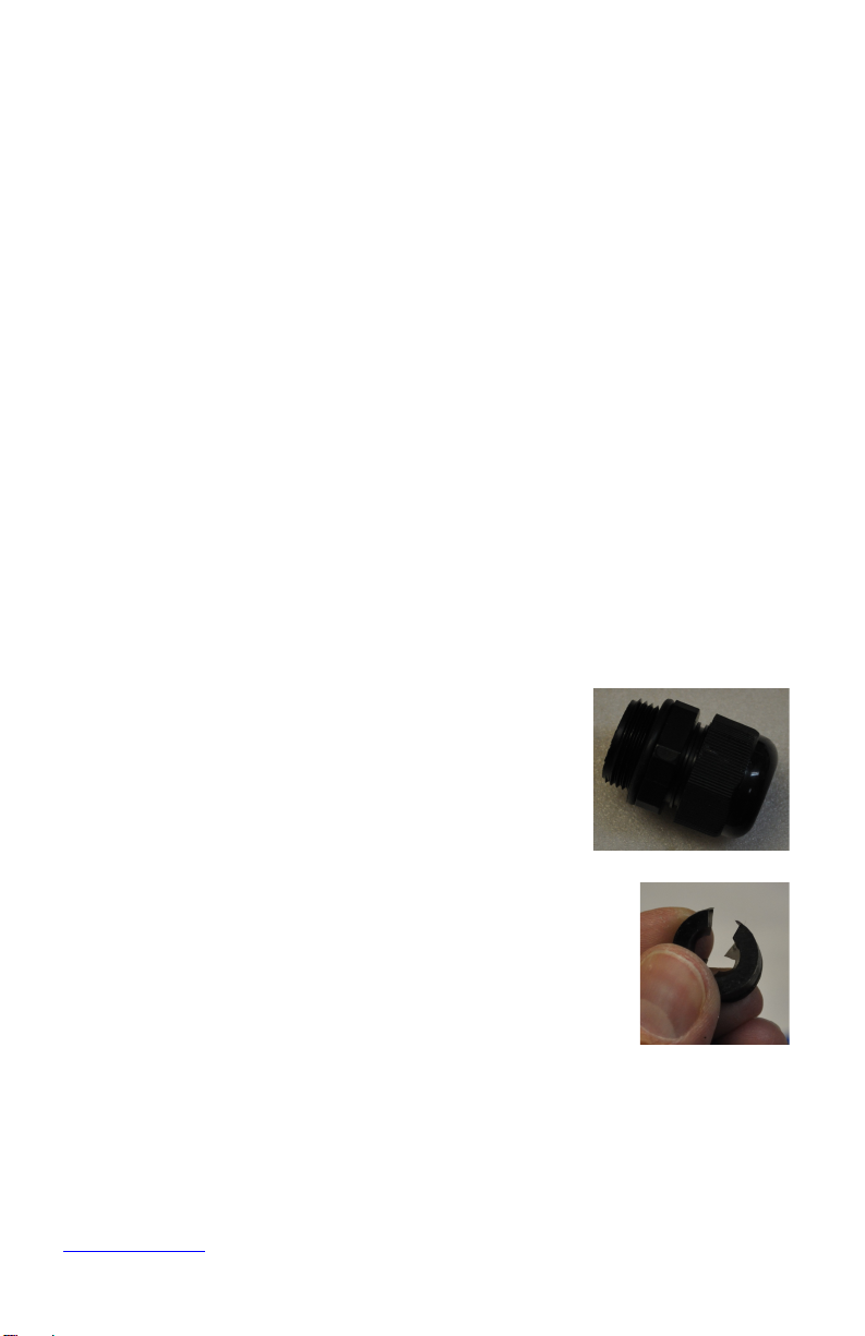
Cable Gland Assembly
Inside the accessory box that came with the
ZipLine, you will find 2 black cable glands that look
like this:
You should unscrew the two parts. You should
leave the small rubber O-ring where it is.
You will notice that the O-ring has a slit in it. This is to
allow the ethernet cable to be completely assembled on
the ground, prior to installing it on the radio.

www.teletics.com 7
This is the order that everything goes together prior on the cable:
The next step is to push the rubber ring into
position so that it will compress when the gland is
assembled. You should GENTLY use a small
screwdriver to slide it inside the main body of the
gland housing until it is flush with the little plastic
fingers at the bottom of the gland, like shown in
the picture to the right->
You can now slide the gland up and down the cable while you plug in the
ethernet connector into the bottom of the radio:
Screw in the gland housing: And then the bottom gland cap:
IMPORTANT!! – Hand tighten gland parts only - Do not use a wrench.

www.teletics.com 8
Bench Testing
When bench testing the ZipLine, you need to know the following:
- The minimum distance between the radios must be 25 feet or 8
meters. If you have the Master and Remote ZipLine closer
together than this during testing, the system may not operate
properly, especially for VoIP services testing.
- You should always orient the radios similarly to how they will be
oriented when they are installed. Optionally, you may sit them
BOTH sideways with the SKY arrow pointing at the same wall to
facilitate easy RJ45 cable installation.
- Both units should be electrically grounded on their chassis to
ensure noise from lights and motors in the vicinity do not affect
signal quality.
- Generally, it is okay to put both ZipLine radios on the bench
facing upwards and a few feet apart when testing. This will bring
the signal strength down to a reasonable level.
- When using the ZipLine with devices with older Ethernet ports
or vintage computers, you may need to be careful about the way
that the Ethernet cables are wired between the injectors and the
customer equipment in use. Some older Ethernet equipment will
not automatically switch when the line connections are reversed.
There are what are called “straight through” Ethernet cables, and
“crossover” Ethernet cables. If the little LEDs on the equipment
RJ45 ports do not light, you may need to use a different type of
Ethernet cable.

www.teletics.com 9
Installation
Mount the ZipLine Radios as high up as possible on both buildings. The
radios must “see” each other without obstructions between them, and
since radio travels in a “football” shape between antennas, you must not
only have a direct path between the antennas, but the path also must be
wide enough, as determined by the distance between the radios:
Radio height required by distance between radios
Distance
(mi./km)
.5 / .80 1 / 1.6 3/5
Minimum Height
( ft/m)
14 / 4.3 19 / 6 35/10
For example, if you have two buildings a half mile apart, the ZipLine
radios should be 14 feet above the ground, plus the height of anything
else that is in between the buildings. So, if there are delivery trucks
moving between the radios, they need to be 14 above the height of the
trucks, so about 30 feet up. Same rule applies for trees, etc.
There are two ZipLine radios included in each kit. There is one Master
unit and one Remote unit. The Remote unit needs to be
connected to the “remote” end. The Master unit needs to be
connected to the main network switch or router at the “main”
location.
Assembly Tips
There are two of everything. Here are some basic set up tips:
It REALLY matters what radio is at what end!!
You can use any other component at either end of the
installation. This includes the ZipLine Power Injectors

www.teletics.com 10
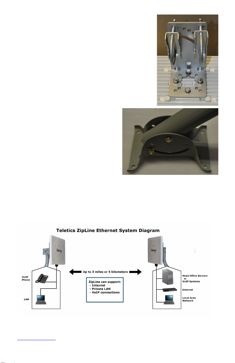
Here is what each end will look like just before you install it:
First, attach
the aluminum
bracket to the
back of the
ZipLine. Use
the 4 10mm
bolts,
washers, and
lock washers
provided:
www.teletics.com 11
Next, put the U-Bolts in place. These are
also packaged in the Accessory Kit (the
white box), and are wrapped in plastic
wrap, along with washers and lock
washers:
The hardware for the pole
mounts is included with the
brackets themselves. Look
for three bolts and 3 nuts in
brass. Here is how you
should put the pieces
together prior to tightening
anything:
Electrical Connections
Here is a diagram of all the components in the ZipLine kit, and how they
hook together:
www.teletics.com 12
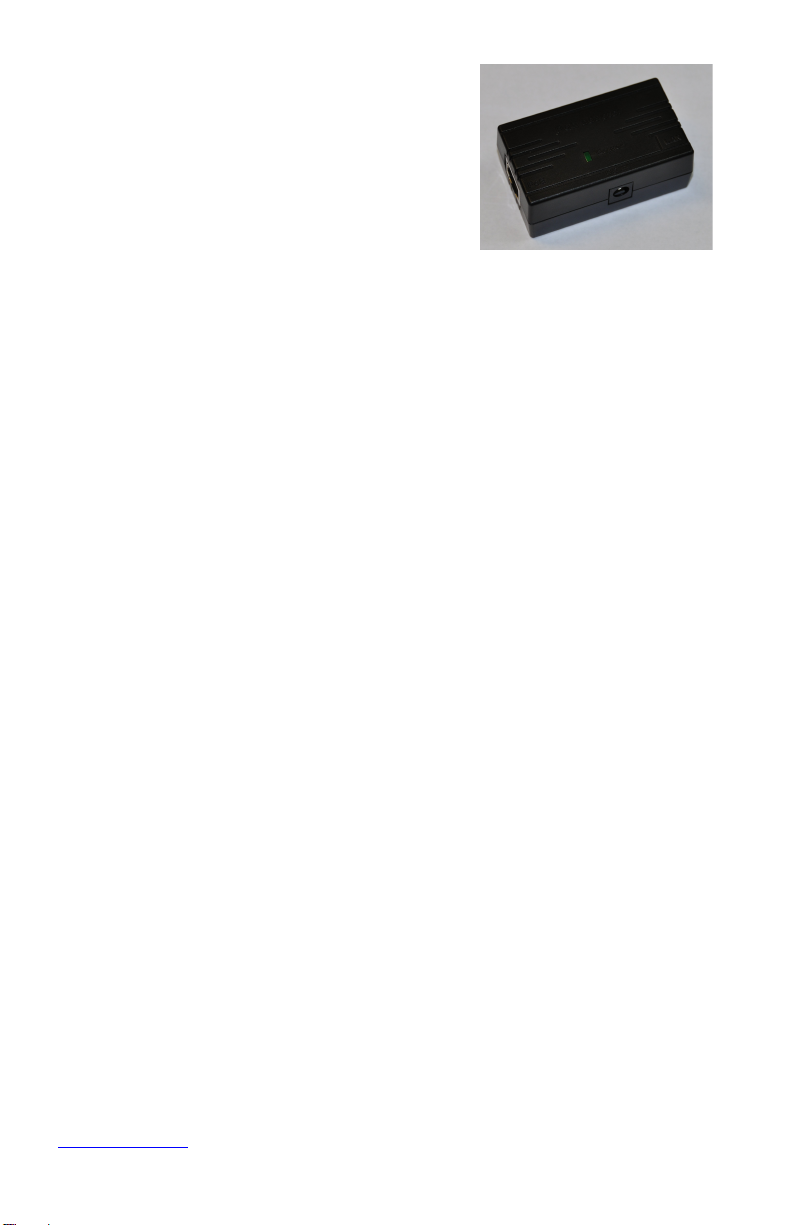
The electrical connection between
the power injectors and the wall
adapters have not been shown for
clarity. Here are what the power
injectors look like:
There are two RJ45 connectors on a
power injector. Please ensure that the outdoor ZipLine Ethernet
eXtreme radio Ethernet cable gets plugged into the side that says
“PoE”. This stands for “Power over Ethernet”, and is how the
outdoor radio gets power. The other Ethernet connector goes
to the cable to the customers laptop, Ethernet switch or
equipment. The little round barrel connector is where the
power adapter gets plugged in.
It does not matter the order in which the radios are powered up.
The RJ45 connection performance is about the same as an office
network LAN connection. It is suitable for email, internet access
etc.
The RJ-45 connection on the Master side may be plugged into an
office router, etc. If the Phone/Remote RJ-45 connection is to be
shared between computers, it is recommended that it is routed
as well, to ensure LAN traffic between computers at the remote
end does not go “over the air”, thereby affecting the performance
of the wireless LAN connection by relaying unnecessary LAN
traffic.
Aiming the antennas
Once you have completed the installation, try to get both radios pointing
at the other as best as you can. It is essential that the radios are
mounted in such a way that the cabling comes out the bottom (towards
the ground).

www.teletics.com 13
The ZipLine antennas allow up to 15 degrees variation in between the
Remote and Master units left/right and up/down. Your aiming does not
have to be perfect to have the system work. You can essentially “eyeball
them in” and get a good, stable signal.
For example, if your ZipLine Remote and Master units are 500
yards/meters apart, and one is mounted 5 feet higher than the other, and
the left/right angle is out by 3 or 4 degrees, you will still have a good
stable link.
Startup / Testing
Once the ZipLine Ethernet eXtreme radios have been installed and
aligned, you may test the system by plugging in a computer at the remote
end and powering it up. It should behave exactly as if it was being used in
the main location.
If you are using the RJ45 data connection as well, you should be able to
use your computer in exactly the same way you would at the other end.
A good check is to get internet access on a laptop at the Master location
end, and simply move the laptop across to the Remote end location and
plug it in. If everything works the same, you are done. If you need
additional tips, see the “Basic Troubleshooting” section, below.
Signal Strength
If you have a laptop, and want to access the internal signal strength utility
inside the ZipLine Ethernet Extreme, you can do so by opening up a
browser window (Internet Explorer, or Firefox) and enter in one of the
following IP addresses in the browser address bar (where you usually
enter a website address):
Enter this if you are at the Master http://169.254.4.11
Enter this if you are at the Remote http://169.254.2.11
www.teletics.com 14
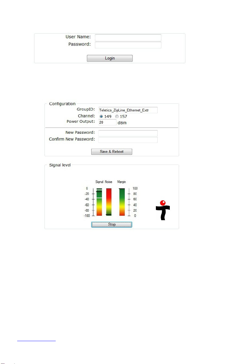
You should see this login screen:
Enter in the user name of “admin” and the password “teletics”. You
should now see the setup/signal strength screen:

www.teletics.com 15
Degraded performance will occur from a Power
Output setting that is too high! Default factory
setting is for 5 km distance between radios. Try
5 or 10 for shorted distances between radios.
If you want to see signal strength, click on the START button underneath
the colored signal strength indicator. You will then see a black signal
strength indicator appear on each of the three gradient color bars, like in
the example screen shot.
What the Numbers Mean
A good signal strength is somewhere between -20 and -60. The ZipLine
Ethernet Extreme will perform well at distances up to 3.5 miles or 5
kilometers. If you have the two ends rather close (say a few hundred
yards or less), you should reduce the output power on both radios, so
you should log into the remote end and change power output and
reboot, then do the same for the master.
A good installation will allow you to get minimum actual data speeds of 50
Mbps, which would allow you to transfer a file of about 600 MB in about
a minute and a half.
The Noise indicator show is there are any other 5.8 GHz equipment
operating in the area. Since the antennas of the ZipLine Ethernet
Extreme are very directional, you most likely will not see any noise even
if other equipment is operating in the area. However, a number of higher
than -60 in this display may indicate an interference source is in the area.
This may not affect the system if you are using it for networking only, but
interference may create problems for VOIP voice communications over
the ZipLine connection.
The Margin display is the mathematical difference between Signal and
Noise.

www.teletics.com 16
Basic Troubleshooting
With Ethernet cables plugged in, you should always get at
least one LED to light up on the Ethernet ports you have
equipment plugged into. If you do not see any LEDs that
light up when you plug in the Ethernet cable, either the
ZipLine Ethernet eXtreme outside unit is not getting power,
or you have a cabling problem.
TUtil ZipLine 58 software is a program that will assist with
the installation and configuration settings of the ZipLine
system. The software and manual may be downloaded from
the Support section of the Teletics website
www.teletics.com/support, or through contacting Teletics
Technical Support. There is no charge for this software.
If you are experiencing any kind of stuttering, sporadic
service, or general bad voice quality during a VoIP phone
call, this may indicate that one of the outdoor units has not
been properly grounded. You need to ground the outside
chassis of the outdoor units in order to ensure a suitable
path to ground, both in the case of a lightning strike, and to
reduce spurious radio noise.
Grounding – The ZipLine is considered to be a low voltage
device, and therefore usually may be installed by anyone
without need for permits or inspections. However, you
need to make certain the outside case is grounded for
lightning reasons, and you should consult your local
electrical / safety codes in your area prior to performing any
kind of permanent equipment installation.
It is important to understand that each ZipLine system is
programmed to ONLY talk to itself. If you have two

www.teletics.com 17
ZipLine systems, you cannot mix and match Remote and
Master units.
If you are experiencing unclear voice or data performance
problems, there is a possibility that the ZipLine is getting
interference from another wireless network near the site.
To check if this is the case download (no charge) and install
on a laptop computer a program called inSSIDer from the
following link: http://www.metageek.net/products/inssider/ If
you need assistance, you may contact your local reseller,
distributor, or Teletics technical support directly by
contacting your regional technical support center, listed on
the Teletics website under Support.
Should you wish to remove the original ZipLine sticker from
the front of the outdoor unit, and replace it with something
else, please ensure that anything installed on the front of the
ZipLine radio allows high frequency radio to pass through.
You cannot use labels that have any kind of metallic based
inks, or a foil label without harming the ZipLine, or seriously
degrading its performance.
If you decide to make your own Ethernet cables, it cannot
be stressed enough that there are two industry standards
for terminating Ethernet cabling. TIA-568A and TIA-568B.
The ZipLine doesn’t care which you use, but you must
decide on which one and crimp all of your Ethernet
connectors the same way.
Running pin 1 to pin 1, pin 2 to pin 2, etc. between the two
Ethernet cable ends without using the TIA-568 A or B
wiring standard will cause your Ethernet connection to
either be very slow, or not work at all.

www.teletics.com 18
Warranty
Teletics warrants the ZipLine system for one year from date of
purchase by the original owner.
Teletics will replace or repair, at its option, any ZipLine system that
fails to perform under normal use, provided that the system is
returned, at the cost of the owner, to Teletics. Items that are
returned for warranty repair must be accompanied by a copy of the
original invoice or proof of purchase. For further details about
how to receive warranty or after warranty service information,
please contact your Teletics distributor, or visit the Teletics
website at www.teletics.com
Any operation of the ZipLine outside of specified temperatures,
power, environment, or in a manner specified in this manual as
harmful to the device will void any warranty. Additionally, any
attempted repair or dismantling of any Teletics product, in any way,
will void all warranties.
In no event shall Teletics liability exceed the original purchase price
of the product from direct, indirect, special, incidental, or
consequential damages resulting from the use, or misuse, of this
product.
Disclaimer
Installation of this equipment must be in strict accordance with the
instructions included in this documentation.
Any changes or modifications made to this device that is not expressly
approved by Teletics may void the user’s authority to operate the
equipment.

www.teletics.com 19
Specifications
Radio Range 3 Miles / 5 kilometers
Ethernet Port RJ45 / 100BT equivalent
Ethernet Speed Port 100BT
Over the air data rate up to 80Mbps
Operating Temperature -40F to +145F (-40C to +60C)
Power Required 19W maximum, 10W typical
Radio Type 5.8 GHz DSSS, License Free
Encryption 256 Bit WPA-PSK (AES)
Radio Power +40 dBm (adjustable)
Radio Sensitivity -80 dBm @ 10-5 BER
Outdoor Unit Size 12” x 12” x 3.5”
( 31cm x 31cm x 9cm )
System Shipping Weight 23 lbs / 10.5 kg

www.teletics.com 20
Customer Support:
www.teletics.com/support
This manual suits for next models
1
Table of contents
Other Teletics Radio manuals


