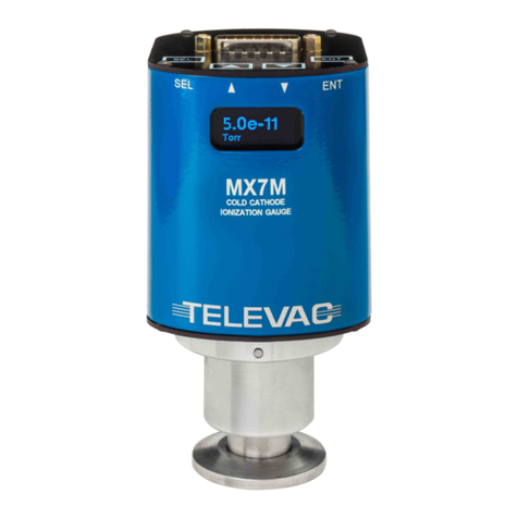
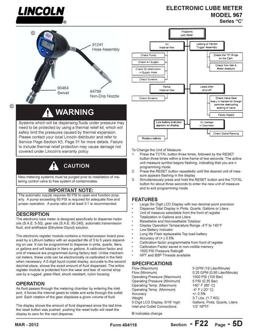
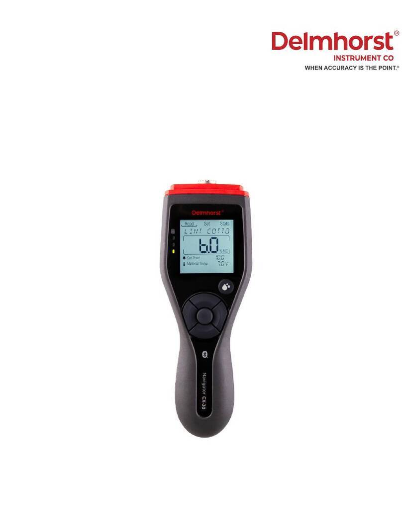
TELEVAC CC-10 User manual

TELEVAC
A DIVISION OF THE FREDERICKS COMPANY
2400 PHILMONT AVE.
HUNTINGDONVALLEY, PA 19006

CC-10
INSTRUMENT MANUAL
CC-10 MANUAL REV D
Page 1 of 40
Y
TELEVA
TABLE OF CONTENTS
SECTION TITLE PAGE
1 Introduction and Safety Instructions
2 User Controls
3 Specifications
4 Operation
5 Analog Output
6 Digital Interface
7 Maintenance
8 I / O Connector
9 Dimensions
10 Error Message List
11 Troubleshooting

CC-10
INSTRUMENT MANUAL
CC-10 MANUAL REV D
Page 2 of 40
Y
TELEVA
1.0
I
n
t
r
odu
c
t
i
on
a
nd
Sa
f
e
t
y
I
n
s
t
r
u
c
t
i
on
s
1.0.1
Product
Overview:
The
CC-10
is
a
self-contained,
compact
wide
range
vacuum
gauge
and
controller
employing
the latest
sensor
technology.
The
CC-10
is
able
to
replace
multiple
traditional
gauges
and
provides the
user
with
measurement
capability
from
atmospheric
pressure
to
10
-9
Torr.
The
gauge
requires
22-26
VDC
input
power
and
provides
the
user
with
a
digital
pressure
indication,
analog
output and
RS485
digital
communications.
Three
independent
set
points
can
be
addressed
from
the instrument‟s
control
panel,
from
a
tethered
remote
display
module
or
via
RS485.
1.2
Sensor
Technology:
The
CC-10
uses
two
sensor
types
to
seamlessly
measure
a
pressure
range
of
12
decades.
An crystal
sensor
is
used
to
measure
from
atmospheric
pressure
to
10
-4
Torr
and
a
double
inverted magnetron
cold
cathode
is
used
to
measure
from
10
-2
to
10
-9
Torr.
1.2.1
Crystal
Sensor
Operating
Principle
The
crystal
sensor
is
a
simple
tuning-folk
shaped
quartz
oscillator
that‟s
similar
to
the
oscillators commonly
used
in
wrist
watches.
The
electrical
impedance
of
the
oscillation
depends
upon
the pressure
of
the
gas
that
surrounds
the
quartz
oscillator,
because
the
resistance
to
the
oscillation
(as
caused
by
friction
between
the
quartz
surface
and
gas
molecule),
varies
as
the
pressure changes.
The
crystal
sensor
measures
the
electrical
impedance
of
the
quartz
oscillator
and
its circuitry
converts
it
to
the
pressure
value.
Crystal
Sensor
1.2.2
Cold
Cathode
Operating
Principle
The
double
inverted
magnetron
cold
cathode
sensor
measures
pressure
by
ionizing
the
residual gases
in
a
magnetron
discharge.
The
body
of
the
sensor
serves
as
the
cathode
ands
is
at
ground potential.
The
anode
operates
at
as
much
as
4000
volts.
A
permanent
magnet
traps
electrons
in the
sensor
to
sustain
the
discharge
at
a
very
low
pressure.
This
type
of
sensor;
like
all
ionization sensors,
is
sensitive
to
gas
type,
but
unlike
conventional
ionization
gauges,
has
no
filaments
to burn
out,
can
operate
continuously
at
higher
pressure
and
is
considerably
more
rugged
and reliable.

CC-10
INSTRUMENT MANUAL
CC-10 MANUAL REV D
Page 3 of 40
Y
TELEVA
1.3
Safety
Instructions
ST
A
RT
B
Y
RE
A
DING
THESE
IMPORT
A
NT
S
A
FETY
INSTRUCTIONS
A
ND
NOTES
T
h
e
s
e
s
a
f
e
t
y
a
l
e
r
t
sy
m
bo
l
s
i
n
t
h
i
s
m
a
nu
a
l
o
r
on
t
h
e
p
r
oduc
t
r
ea
r
p
a
n
e
l
m
ea
n C
a
u
t
io
n
s
-
p
e
r
so
n
a
l
s
a
fe
t
y,
p
r
o
p
e
r
t
y
d
a
m
a
ge
o
r
d
a
n
ge
r
f
r
o
m
elec
t
r
ic
a
l
s
h
oc
k
.
R
e
a
d
t
h
ese
i
n
s
t
r
u
c
t
io
n
s
c
a
r
ef
u
lly.
In
these
instructions
the
word
“product”
refers
to
the
CC-10
and
all
of
its
approved
parts
and
accessories.
NOTE
:
T
h
e
s
e
i
ns
t
r
uc
t
i
ons
do
no
t
a
nd
c
a
nno
t
p
r
ov
i
d
e
f
o
r
e
v
e
r
y
con
t
i
ng
e
ncy
t
h
a
t
m
a
y
a
r
i
s
e
i
n
conn
e
c
t
i
on
w
i
t
h
t
h
e
i
ns
t
a
ll
a
t
i
on
,
op
e
r
a
t
i
on
,
o
r
m
a
i
n
t
e
n
a
nc
e
o
f
t
h
i
s
p
r
oduc
t
.
S
hou
l
d
you
r
e
qu
i
r
e
f
u
r
t
h
e
r
a
ss
i
s
t
a
nc
e,
p
l
ea
s
e
con
t
a
c
t
Te
l
e
v
a
c
a
t
t
h
e
a
dd
r
e
ss
on
t
h
e
t
i
t
l
e
p
a
g
e
o
f
t
h
i
s
m
a
nu
a
l
.
This
product
has
been
designed
and
tested
to
offer
reasonably
safe
service
provided
in
it‟s
installed,
operated
and
serviced
in
strict
accordance
with
these
safety
instructions.
F
a
il
u
r
e
t
o
co
m
p
ly
wi
t
h
t
h
ese
i
n
s
t
r
u
c
t
io
n
s
m
a
y
r
es
u
l
t
i
n
se
r
io
u
s
p
e
r
so
n
a
l
i
n
j
u
r
y,
i
n
cl
ud
i
n
g
d
e
a
t
h
,
o
r
p
r
o
p
e
r
t
y
d
a
m
a
ge.
These
safety
precautions
must
be
observed
during
all
phases
of
operation,
installation,
and
service
of
this
product.
Failure to
comply
with
these
precautions
or
with
specific
warnings
elsewhere
in
this
manual
violates
safety
standards
of
design,
manufacture,
and
intended
use
of
the
instrument.
Televac
disclaims
all
liability
for
the
customer‟s
failure
to
comply
with these
requirements.
Th
e
se
r
vice
a
nd
r
e
p
a
i
r
i
n
fo
r
m
a
t
io
n
i
n
t
h
is
m
a
nu
a
l
is
fo
r
t
h
e
u
se
of
Q
u
a
lifie
d
Se
r
vice
P
e
r
so
nn
el.
T
o
a
voi
d
s
h
oc
k
,
d
o
n
o
t
p
e
r
fo
r
m
a
n
y
p
r
oce
du
r
es
i
n
t
h
is
m
a
nu
a
l
o
r
p
e
r
fo
r
m
a
n
y Se
r
vici
n
g
o
n
t
h
is
p
r
o
du
c
t
un
less
yo
u
a
r
e
qu
a
lifie
d
t
o
d
o
so.
√
RE
A
D
I
n
s
t
r
u
c
t
i
on
s
–
Read
all
safety
and
operating
instructions
before
operating
the
product.
√
RET
A
IN
i
n
s
t
r
u
c
t
i
on
s
–
Retain
the
Safety
and
Operating
Instructions
for
future
reference.
√
HEED
w
a
r
n
i
ng
s
–
Adhere
to
all
warnings
on
the
product
and
in
the
operating
instructions.
√
FO
LL
OW
i
n
s
t
r
u
c
t
i
on
s
–
Follow
all
operating
and
maintenance
instructions.
√
A
CCESORIES
–
Do
not
use
accessories
not
recommended
in
this
manual
as
they
may
require
a
technician
to
restore
the
product
to
its
normal
operation.
T
o
r
e
du
ce
r
is
k
of
fi
r
e
o
r
elec
t
r
ic
s
h
oc
k
,
d
o
n
o
t
ex
p
ose
t
h
is
p
r
o
du
c
t
t
o
r
a
i
n
o
r
m
ois
t
u
r
e.

CC-10
INSTRUMENT MANUAL
CC-10 MANUAL REV D
Page 4 of 40
Y
TELEVA
Safety
Instructions
(cont.)
O
b
j
ec
t
s
a
nd
L
i
qu
i
d
En
t
r
y
–
Neve
r
pu
s
h
o
b
j
ec
t
s
of
a
n
y
k
i
nd
i
n
t
o
t
h
is
p
r
o
du
c
t
t
h
r
o
u
g
h
o
p
e
n
i
n
gs
a
s
t
h
ey
m
a
y
t
o
u
c
h
d
a
n
ge
r
o
u
s
vol
t
a
ge
p
oi
n
t
s
o
r
s
h
o
r
t
o
u
t
p
a
r
t
s
t
h
a
t
co
u
l
d
r
es
u
l
t
i
n
a
fi
r
e
o
r
elec
t
r
ic
s
h
oc
k
.
Be
c
a
r
ef
u
l
n
o
t
t
o
s
p
ill
li
qu
i
d
of
a
n
y
k
i
nd
o
n
t
o
t
h
e
p
r
o
du
c
t
s.
D
o
no
t
subs
t
i
t
u
t
e
p
a
r
t
s
o
r
m
od
i
f
y
i
ns
t
r
u
m
e
n
t
.
B
e
c
a
us
e
o
f
t
h
e
d
a
ng
e
r
on
i
n
t
r
oduc
i
ng
a
dd
i
t
i
on
a
l
h
aza
r
ds
,
do
no
t
i
ns
t
a
ll
subs
t
i
t
u
t
e
p
a
r
t
s
o
r
p
e
r
f
o
r
m
a
ny
un
a
u
t
ho
r
i
ze
d
m
od
i
f
i
c
a
t
i
ons
t
o
t
h
e
p
r
oduc
t
.
Re
t
u
r
n
t
h
e
p
r
oduc
t
t
o
Te
l
e
v
a
c
f
o
r
s
e
r
v
i
c
e
a
nd
r
e
p
a
i
r
t
o
e
nsu
r
e
t
h
a
t
s
a
f
e
t
y
f
ea
t
u
r
e
s
a
r
e
m
a
i
n
t
a
i
n
e
d
.
D
o
no
t
us
e
t
h
i
s
p
r
oduc
t
i
f
i
t
h
a
s
un
a
u
t
ho
r
i
ze
d
m
od
i
f
i
c
a
t
i
ons
.

CC-10
INSTRUMENT MANUAL
CC-10 MANUAL REV D
Page 5 of 40
Y
TELEVA
2.0
U
s
e
r
C
on
t
r
o
l
s
2.1
F
r
on
t
p
a
n
e
l
1. Pressure indicator
2. Set point status indicator
3. High Voltage status indicator
4. Function key
5. Up key
6. Shift key
7. Enter key
8. I/O connector
2
5
4
1
7
8
3
6

CC-10
INSTRUMENT MANUAL
CC-10 MANUAL REV D
Page 6 of 40
Y
TELEVA
2.2
Rea
r
p
a
n
e
l
2.3
Se
nso
r
1. Sensor access
screws
screws
1. Anti rotation slot
2. Anode pin
3. Crystal sensor pins
4. Ground pins
1
1
4
2
3

CC-10
INSTRUMENT MANUAL
CC-10 MANUAL REV D
Page 7 of 40
Y
TELEVA
3.0
S
p
e
c
i
f
i
c
a
t
i
on
s
Measurement range
760 Torr to 1 X 10⁻⁹ Torr
Accuracy
±0.2 of decade 10E-9 to 10E-3 Torr
±15% 2 X 10E-3 to 1 X 10E-1
±10% 2 X 10E-1 to 1 X 10E Torr
±5% 10 to 760
Pressure display
Digital display of two mantissa digits and two exponent digits
Pressure unit
Torr / Pascal selectable
Set point
Three set points
(one independent set point and two common ground set points)
Setting method: 1 By local switches
2. Through communication interface
Contact rating: DC50V 0.12A
Analog output
Log or combined output selectable
Voltage: 0 –10V
Ambient temperature & Humidity
(operating)
0-50C / 10-90% RH
Power requirement
22-26vdc
Power consumption
8w maximum
Weight
1.54 lbs. (NW25 model)
Size
3.7” wide X 2/78” deep X 6.3” high (NW25 model)
NOTE: Bake temperature: Max. 150°C (with electronics module removed).

CC-10
INSTRUMENT MANUAL
CC-10 MANUAL REV D
Page 8 of 40
Y
TELEVA
4.0
O
p
e
r
a
t
i
on
4.1
Starting
the
measurement
Connect
D
sub-connector
to
the
instrument
and
supply
power
after
installing
CC-10
to
the vacuum
system
and
properly
connecting
necessary
wires. When
the
power
is
supplied
the
unit
runs
an
internal
check
program
for
several
seconds
then goes
to
measurement
mode.
Pressure
display
will
appear
on
the
display.
4.2
Locking
parameters In
order
to
prevent
unintended
parameter
changing
the
“parameter
lock”
function
is
provided.
To switch
this
function
between
enabled
and
disabled
follow
the
procedure
below.
When
shipped,
it
is
set
to
disabled.
4.3
Display
modes
and
mode
changing
There
are
nine
modes
that
are
changed
by
pushing
[FUNC]
key
and
[ENT]
key.
Those
are;
1.
Measurement
mode
2.
SP1
setting
mode
(SP1L
setting,
SP1H
setting)
3.
SP2
setting
mode
(SP2L
setting,
SP2H
setting)
4.
SP3
setting
mode
(SP3L
setting,
SP3H
setting)
5.
Crystal
gauge
ATM
(atmospheric
pressure)
adjustment
mode
(Manual
operation)
6.
Crystal
gauge
Zero
adjustment
mode
(Manual
operation)
7.
Analog
output
setting
mode
8.
Pressure
unit
selection
mode
9. Communications
set
mode
10.
Crystal sensor property mode
When in the measure mode, push “ “ key, and “→” key,
“ENT” key simultaneously.
SP1
SP2
SP3
HV
FUNC
X 10
Torr
ENT
All LEDs are lit for a moment, then established status
will alter.
PUSH
SIMULTANEOUSLY
SP3
SP2
SP1
X 10
Torr
ENT
FUNC
Lit
HV

CC-10
INSTRUMENT MANUAL
CC-10 MANUAL REV D
Page 9 of 40
Y
TELEVA
Changing
modes
(1)
By
pushing
[FUNC]
key
the
mode
moves
cyclically
as;
1
→
2
→
3
→
4
→
5
→
6→7
→
8
→9→1
(2)
When
the
mode
moves
to
SPx(x
is
1,2
or
3)
set
mode,
SPxL
set
is
selected
first.
Pushing
[ENT]
key
stores
the
value
and
moves
to
SPxH
set
mode.
In
SPxH
mode
by
pushing
[ENT]
key the
value
is
stored
then
it
returns
to
measure
mode.
*If
[FUNC]
key
is
pushed
instead
of
[ENT]
button
in
either
SPxL
or
SPxH
mode
the
value
is
not stored
and
the
mode
moves
to
the
next
one.
(3)
In
any
other
mode
than
SPx
set
modes,
by
pushing
[ENT]
key
the
value
is
stored
and
the mode
returns
to
the
measure
mode.
(If
[FUNC]
key
is
pushed
instead,
the
value
is
not
stored and
the
mode
moves
to
the
next
mode.
(4)
If,
in
any
program
mode,
there
are
no
operation
for
30
seconds
it
automatically
moves
back to
measure
mode. (There are some exceptions)
MEASURE MODE
SP1 SET MODE
SP1L
SP1H
ENT
SP2 SET MODE
SP2L
SP2H
FUNC
SP3 SET MODE
SP3L
SP3H
ATM ADJUST MODE
XTAL ZERO ADJUST MODE
ANALOG OUTPUT SET MODE
PRESSURE UNIT SELECT MODE
COMMUNICATION SET MODE
ADDRESS
BAUD RATE
ENT
PARITY RATE
STOP BIT
ENT
ENT
CRYSTAL SENSOR PROPERTY SET MODE
O6on
ENT
XXXX*
YYYY*
ENT
FUNC
FUNC
FUNC
FUNC
FUNC
FUNC
FUNC
FUNC
*4 digit numbers specific to the sensor
FUNC
ENT
ENT
ENT
ENT
ENT
ENT
ENT
ENT
ENT
1
2
3
4
5
6
7
8
9
10

CC-10
INSTRUMENT MANUAL
CC-10 MANUAL REV D
Page 10 of 40
Y
TELEVA
4.4
Set
Point
General
Description
–There
are
3
set
points
in
this
instrument
and
each
set
point
has
hysteresis
characteristics
and consists
of
two
set
values;
upper
threshold
and
lower
threshold.
In
this
manual
the
upper threshold
value
of
the
set
point
1
is
expressed
as
SP1H
and
lower
threshold
as
SP1L.
LED‟s
on
the
front
panel
displays
the
status
of
each
set
point.
They
lit
when
the
pressure
reaches
at
the lower
threshold
and
at
the
same
time
set
point
relays
activate.
If
the
pressure
rises
again
and exceeds
upper
threshold
the
LED‟s
go
off
and
the
relays
deactivate.
The
both
threshold
value
of each
3
set
point
can
be
set
independently.
Set
value
of
set
points
Upper
threshold
of
each
set
point
(SP1H-SP3H)
cannot
be
set
below
the
lower
threshold
value
(SP1L-SP3L).
If
it
does
not
meet
this
condition
the
upper
and
the
lower
threshold
become
the same
value.
Hysteresis The
hysteresis
characteristic
is
installed
to
prevent
chattering
of
the
relays.
Therefore,
there
are some
response
differences
near
the
set
point.
Pressure
Hysteresis
Setpoint Status
SP1L
(Lower Threshold)
SP1H
(Upper Threshold)
ON
OFF

CC-10
INSTRUMENT MANUAL
CC-10 MANUAL REV D
Page 11 of 40
Y
TELEVA
4.5
Explanation
of
each
mode
Measurement
Mode
Pressure
is
displayed
on
the
main
display
and
the
status
of
SP
(set
point)
and
HV
(high
voltage)
are
indicated
by
LED
lamp. Whenever
power
is
turned
on
this
mode
is
selected
first. Also
the
unit
returns
to
this
mode
when
one
of
the
following
situations
is
happened.
(1)
In
any
program
modes
when
a
set
of
the
parameters
are
stored
by
pushing
[ENT]
key or
(2)
When
the
unit
travels
through
all
modes
by
pushing
[FUNC]
key
one
after
another. or
(3)
While
in
program
mode
and
there
is
no
operation
for
about
30
second.
SP1
SP2
SP3
HV
Pa
ENT
X10
FUNC
Pressure is displayed
Status of SP1, SP2, SP3 and HV are indicated by LED lamp.

CC-10
INSTRUMENT MANUAL
CC-10 MANUAL REV D
Page 12 of 40
Y
TELEVA
SP1
Set
Mode
In
this
mode
value
of
SP1L
and
SP1H
can
be
set.
SP1
SP2
SP3
HV
SP2
SP1
SP3
HV
HV
SP2
SP1
SP3
SP3
SP2
SP1
HV
X10
Torr
Torr
Torr
Torr
X10
X10
X10
FUNC
FUNC
FUNC
FUNC
ENT
ENT
ENT
ENT
Select SP1H
Select SP1H
Select SP1L
Select SP1L
SP1
mode
:
When
“parameter
lock”
is
enabled
any
parameter
change
can
not be
done
and
only
displaying
the
current
parameters
is
possible.
Make
sure
if lock
is
disabled
before
the
programming.
(Refer
to
4.2)
SP1
lamp
blinks
when
SP1
setting
mode
is
selected.
Characters
of
“SP
1L”appear
in
the
main
display
then
the
pre
set
value
appears.
The
first
digit
of
the mantissa
blinks.
To
change
the
set
value,
follow
the
procedures
below.
(1)
Select
the
digit
to
be
changed
by
horizontal
arrow
key
[→].
(2)
Change
the
value
by
vertical
arrow
key
[↑].
(3)
By
pushing
[ENT]
key
the
unit
moves
to
SP1H
set
mode.
*
If,
instead,
[FUNC]
key
is
pushed
the
unit
skips
SP1H
then
moves
to SP2L
mode.
Note
that
the
new
set
value
of
SP1L
is
not
stored
in
this operation.
When
SP1L
is
determined
the
unit
moves
to
SP1H
set
mode. The
character
of
“SP
1H”
is
shown
in
the
display
then
the
pre-set
value
is appears.
The
first
digit
will
blinks
prompting
the
entry
of
the
new
value.
To
change
the
set
value,
follow
the
procedures
below.
(1)
Select
the
digit
to
be
changed
by
horizontal
arrow
key
[→].
(2)
Change
the
value
by
vertical
arrow key ↑
(3)
By
pushing
[ENT]
key
the
values
of
both
SP1L
and
SP1H
are
registered
and
the
unit
returns
to
measure
mode.
*
If,
instead,
[FUNC]
key
is
pushed
the
values
are
not
registered
and
the
unit moves
to
SP2L
mode.
Lit
Blink
Blink
Blink
Blink
Lit
Blink
Blink

CC-10
INSTRUMENT MANUAL
CC-10 MANUAL REV D
Page 13 of 40
Y
TELEVA
SP2
,SP3
Setting
Mode The
settings
of
SP2L,
SP2H,
SP3L
and
SP3H
are
possible.
Follow
the
same
procedure
as SP1L/SP1H
setting.
The
crystal
gauge
atmospheric
pressure
adjust
mode The
crystal
sensor
which
covers
pressures
from
Atmosphere
to
about
10
millitorr
need
to
be calibrated
at
atmosphere
when
the
instrument
is
first
installed. Because
the
gauge
is
factory
calibrated
before
shipment,
the
calibration
at
user
site
is
not
usually necessary
unless
the
physical
elevation
of
the
user‟s
location
is
substantially
above
sea
level. When
the
crystal
sensor
is
replaced
for
maintenance
or
if
the
displayed
value
at
atmosphere
is shifted,
perform
the
calibration
as
follows.
T
h
e
c
r
ys
t
a
l
g
a
ug
e
a
t
m
osph
e
r
i
c
p
r
e
ssu
r
e
a
d
j
us
t
m
e
n
t
m
od
e
:
when
“parameter
lock”
is enabled
this
adjustment
is
not
possible.
Make
sure
if
lock
is
disabled
before
the programming.
(Refer
to
4.2)
Note: The same adjustment can be triggered from I/O pin #14. See section 8.
HV
SP2
SP1
SP3
SP3
SP2
SP1
HV
Torr
Torr
X10
X10
FUNC
FUNC
ENT
ENT
Blink
Crystal Gauge
ATM Adjust Mode
Crystal Gauge
ATM Adjust Mode
Lit Blink
The
character
“01
on”
on
the
display
shows
the
unit
is
in
this
mode
Make
sure
the
system
is
vented
to
atmosphere
then
push
[ENT] key.
It
triggers
the
adjustment,
instructing
the
sensor
to
fit
the measurement
to
the
pre-set
atmosphere
value
at
the
event.
*As
to
the
pre-set
atmosphere
value
see
below.
Note:
If,
by
some
mis-operation,
the
adjustment
is
triggered
when the
system
is
in
vacuum
“ErrA”
is
displayed
and
the
adjustment
will not
be
completed.
The
unit
regards
the
crystal
sensor
signal
as
the
pre-set atmosphere
pressure
and
adjusts
the
measurement
to
fit
the
value. The
default
atmospheric
pressure
value
is
760
Torr.
If
actual atmospheric
pressure
is
considerably
different
from
760Torr
(for instance
a
high
altitude
locale)
changing
the
atmosphere
value
is
necessary. To
change
the
Atmosphere
value
setting,
follow
the
procedure below.
(1) Push horizontal arrow key [→] to indicate the current set value.
(The
set
value
is
displayed
in
Torr
unit.)
The
first
digit
will
blink.
(2)
Select
the
digit
to
be
changed
with
[→]
key.
Then
select
the
value
by
vertical
arrow
key[↑].
(3)
Push
[ENT]
key
to
register
the
new
set
value.
The
unit
returns to
measure
mode.
*
These
procedures
only
change
the
Atmosphere
pressure
value. To
perform
the
Atmospheric
pressure
adjustment,
enter
this
mode again
and
press
[ENT]
key.
*
When
the
unit
shipped
the
value
is
set
at
760
Torr.
This procedure
is
not
necessary
unless
the
customer
site
is
high
above sea
level
and
the
Atmosphere
pressure
is
much
lower
than
760
Torr.
8-5

CC-10
INSTRUMENT MANUAL
CC-10 MANUAL REV D
Page 14 of 40
Y
TELEVA
Crystal
gauge
zero
adjustment
mode In
this
mode,
it
is
possible
to
manually
make
a
zero
adjustment
of
the
crystal
gauge. Usually
this
adjustment
is
not
necessary,
because
it
is
performed
automatically
every
time
the
pressure
reaches
3.0
x
10-3
Torr.
When
the
crystal
sensor
is
replaced
for
maintenance
or
if
the zero
has
shifted,
a
manual
zero
adjustment
might
be
required.
C
r
ys
t
a
l
g
a
ug
e
Ze
r
o
a
d
j
us
t
m
e
n
t
m
od
e
:
When
“parameter
lock”
is
enabled
this
adjustment is
not
possible.
Make
sure
if
lock
is
disabled
before
the
programming.
(Refer
to
4.2)
The
character
“02
on”
on
the
display
shows
the
unit
is
in
this
mode.
Pushing
[ENT]
key triggers
the
zero
adjustment
instructing
the
sensor
to
fit
the
measurement
to
zero
at
the event.
Note: The same adjustment can be triggered from I/O pin #6. See section 8.
Analog
output
setting
mode. The
analog
output
can
be
selected
from
the
Log
output
mode
or
the
combined
output
mode. When
the
Log
output
is
selected,
it
is
necessary
to
set
the
width
voltage
of
one
decade
and
the
full
scale
voltage.
If
the
optional
display
unit
DS-10
is
used,
the
output
mode
will
have
to be
set
accordingly.
In
this
section
only
the
operation
will
be
explained.
A
detail
of
the
analog
output
is
described in
the
next
section.
T
h
e
a
n
a
l
og
ou
t
pu
t
s
e
tt
i
ng
m
od
e
:
When
“parameter
lock”
is
enabled
any
parameter
change can
not
be
done
and
only
displaying
the
current
parameters
is
possible.
Make
sure
if
lock
is disabled
before
the
programming.
(Refer
to
4.2)
HV
SP2
SP1
SP3
Torr
X10
FUNC
ENT
Select Output Mode
Lit Blink
8-7
When
the
analog
output
setting
mode
is
selected,
“03”
is
appear
on the
left
side
two
digit
of
the
display.
The
right
side
two
digit
of
the display
blink
and
show
the
out
put
mode.
01:
Log
output
02:
Combined
output
03:
Output
for
the
display
unit DS-10.
The
change
of
the
setting
should
be
made
according
to
the
following
procedures.

CC-10
INSTRUMENT MANUAL
CC-10 MANUAL REV D
Page 15 of 40
Y
TELEVA
SP1
SP2
SP3
HV
SP2
SP1
SP3
HV
HV
SP2
SP1
SP3
SP3
SP2
SP1
HV
X10
Torr
Torr
Torr
Torr
X10
X10
X10
FUNC
FUNC
FUNC
FUNC
ENT
ENT
ENT
ENT
Set Full Scale
Set 1 decade
voltage
Set Full Scale
Set 1 decade
voltage
SP3
SP2
SP1
HV
Torr
X10
FUNC
ENT
Select
Combined Mode
For Output
Lit Blink
Lit Blink
Lit Blink
Lit Blink
Lit Blink
To
select
the
Log
output
mode
and
set
the
width
of
one
decade
0.5(V)
(Width
of
one
decade
can
be
set
either
0.5V
or
1.0V.)
(1)
Set
the
blinking
display
to
01
by
[↑]
key
then
push
[ENT]
key
to
select
Log
output
mode.
(2)
Blinking
value
becomes
to
show
the
one
decade
width.
Set
the value
0.5(V)
then
push
[ENT]
key.
3)
Blinking
value
becomes
to
show
the
full
scale
voltage.
Set
the value
between
7
to
10V
then
push
[ENT]
key.
The
unit
returns
to measure
mode.
To
select
the
Log
output
mode
and
set
the
width
of
one
decade
1.0(V)
(1)
Set
the
blinking
display
to
01
by
[↑]
key
then
push
[ENT]
key
to
select
Log
output
mode.
(2)
Blinking
value
becomes
to
show
the
one
decade
width.
Set
the value
1.0(V)
then
push
[ENT]
key.
(3)
Blinking
value
becomes
to
show
the
full
scale
pressure.
When
1.0V
decade
is
selected
maximum
voltage
is
automatically
set
to
10V
and
full
scale
pressure
corresponding
to
10V
can
be
set
here.
Select
value
from
00(1.0x10
0
Torr)
to
03(1.0x10
3
Torr).
Push
[ENT]
key
to
register
the
value
after
selecting
the
full
scale
pressure.
The
unit returns
to
measure
mode.
To
select
the
combined
output
mode
set
the
blinking
digit
at
02
by
[↑]
key
then
push
[ENT]
key
to
register
the
mode.
The
unit
returns
to
measure
mode.

CC-10
INSTRUMENT MANUAL
CC-10 MANUAL REV D
Page 16 of 40
Y
TELEVA
When
“parameter
lock”
is
enabled
the
current
parameter
is
displayed
in
the
right
side
two digits.
01:
Log
output
->
Width
of
one
decade
->
full
scale
02:
combined
output
03:
out
put
for
DS-10
display
unit
Explanation
of
the
output
full
scale If
the
Log
output
is
selected
and
the
width
of
one
decade
is
set
to
0.5(V),
the
range
of
the output
voltage
corresponding
to
the
effective
voltage
of
1V
to
10V
is
shown
in
the
figure below.
0.5V/decade
x
12
decade=
6V
If
the
Log
output
is
selected
and
the
width
of
one
decade
is
set
to
1.0(V),
the
range
of
the
output
voltage
corresponding
to
the
effective
voltage
of
1V
to
10V
is
shown
in
the
figure
below.
1.0V/decade
x
12
decade=
12V
SP3
SP2
SP1
HV
Torr
X10
FUNC
ENT
Output to display
unit
Lit Blink
To
select
output
for
DS-10
display
unit
set
the
right
side
two
digits that
are
blinking
at
03
then
push
[ENT]
key
to
register
the
parameter. The
unit
returns
to
measure
mode.
Effective voltage range (V)
ATM set at 10 V
ATM set at 9 V
ATM set at 8 V
ATM set at 7 V
10-9
10-7
10-5
10-3
10-1
101
103 Torr
10-9 Torr
10-9 Torr
10-9 Torr
10-9 Torr
103 Torr
103 Torr
103 Torr
103 Torr
1
2
3
4
5
6
7
8
9
10

CC-10
INSTRUMENT MANUAL
CC-10 MANUAL REV D
Page 17 of 40
Y
TELEVA
103Torr
101
10-1
10-3
10-5
10-7
10-9
1
2
3
5
6
7
8
9
4
10
Effective voltage range (V)
Set 10V = 10 2(0) Pa (Torr)
Set 10V = 10 3(1) Pa (Torr)
Set 10V = 10 4(2) Pa (Torr)
Set 10V = 10 5(3) Pa (Torr)
10-9 Torr
10-8 Torr
10-7 Torr
10-6 Torr
100 Torr
101Torr
102Torr
103 Torr

CC-10
INSTRUMENT MANUAL
CC-10 MANUAL REV D
Page 18 of 40
Y
TELEVA
P
r
e
ssu
r
e
un
i
t
s
e
l
e
c
t
i
on
m
od
e
It
is
a
mode
the
pressure
unit
can
be
selected.
Pa,
Torr
and
mbar
are
available.
Blink
SP3
SP2
SP1
HV
X10
Lit Blink
04
is
displayed
on
the
left
side
two
digits
to
show
pressure
unit
selection
mode
is
selected.
On
the
right
side
two
digits
selected
unit
is
displayed.
01: Pa
02: Torr
03: mbar
To
change
the
unit
select
the
value
by
the
[↑]
arrow
key
then
push
[ENT]
key
to
register
the
parameter.
The
unit
returns
to
measure
mode.
T
h
e
p
r
e
ssu
r
e
un
i
t
s
e
l
e
c
t
i
on
m
od
e
:
When
“parameter
lock”
is
enabled
any
parameter
change
can
not
be
done
and
only
displaying
the
current
parameters
is
possible.
Make
sure
if
lock
is
disabled
before
the
programming.
(Refer
to
4.2)
N
o
t
e
s
:
Note
that
the
numerical
set
values
(for
instance
set
point
values)
are
not changed
even
if
the
unit
is
changed.
ENT
FUNC

CC-10
INSTRUMENT MANUAL
CC-10 MANUAL REV D
Page 19 of 40
Y
TELEVA
C
o
mm
un
i
c
a
t
i
on
s
e
tt
i
ng
m
od
e To
communicate
with
the
host
computers,
address,
boud
rate,
parity
bit
and
stop
bit
are
to
be programmed.
Follow
the
procedures
below. Note:
As
to
the
communication
functions
refer
to
the
section
5.
SP1
SP2
SP3
HV
SP2
SP1
SP3
HV
HV
SP2
SP1
SP3
SP3
SP2
SP1
HV
X10
Pa
Pa
Pa
Pa
X10
X10
X10
FUNC
FUNC
FUNC
FUNC
ENT
ENT
ENT
ENT
Display stop
bit
Display
parity bit
Display rate
Display
address
Lit Blink
Lit Blink
Lit Blink
Lit Blink
Communication
setting
mode
: When
“parameter
lock”
is
enabled
any
parameter
change
can
not
be
done
and only
displaying
the
current
parameters
is
possible. In
this
case
by
pushing
ENT
key,
the
display
in
the
right
two
digits
will
be
changed
in
the
following
order;
address,
data
rate,
parity
bit
then
stop
bit. Make
sure
that
the
lock
is
disabled
if
you
need
the
programming.
“05”
display
appears
on
the
left
two
digits
that
means
the
gauge
is
in communication
setting
mode.
The
right
two
digits
(blinking)
show
the
address value
(00
–
0F)
.
To
change
the
parameter
settings,
follow
the
procedures
below.
(1)
Address Changing
the
number
in
the
blinking
digits
by
the
vertical
arrow
key
[↑]
then push
ENT
key.
The
address
setting
is
stored
and
the
unit
moves
to
the
data
rate
select
mode.
(2)
Data
Rate Select
the
data
rate
in
the
blinking
digits
by
the
vertical
arrow
key
[↑]
then push
ENT
key.
The
data
rate
setting
is
stored
and
the
unit
moves
to
the
parity bit
select
mode.
Note:
Selectable
data
rates
are
12(1200bps),
48(4800bps),
96(9600bps),
19(19200bps)
and
38(38400bps).
(3)
Parity
bit Select
the
parity
bit
in
the
blinking
digits
by
the
vertical
arrow
key
[↑]
then
push ENT
key.
The
parity
bit
setting
is
stored
and
the
unit
moves
to
the
stop
bit
select mode.
Note:
Selectable
parity
bit
settings
are
00(none),
01(odd)
and
02(even).
(4)
Stop
bit Select
the
stop
bit
in
the
blinking
digits
by
the
vertical
arrow
key
[↑]
then
push ENT
key.
The
stop
bit
setting
is
stored
and
the
unit
moves
to
the
measure
mode. Note:
Selectable
stop bit
settings
are
01(1
bit)
and
02(2
bits).
*
If
FUNC
key
is
pushed
instead
of
ENT
key,
the
unit
skips
the
rest
of
the
communication
setting
and
return
to
measure
mode.
Note
that
the
settings
are not
stored.
Table of contents
Other TELEVAC Measuring Instrument manuals
