TELEVAC MX7B User manual

©2022 Televac® - The Fredericks Company | www.televac.com | sales@televac.com | +1 215 947 2500 mx7b_im rev E Page 1of 23
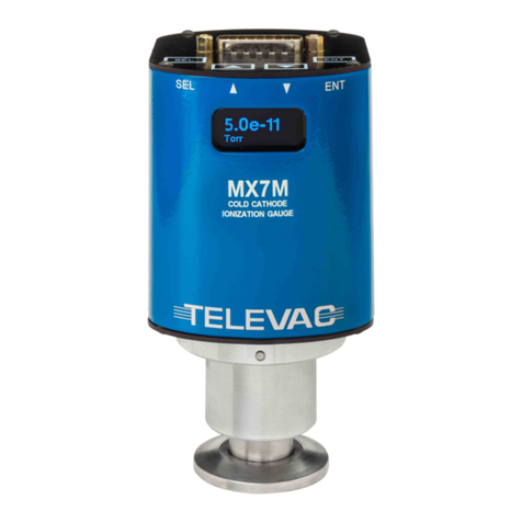
MX7B Cold Cathode Ionization Gauge
Instruction Manual
Rev E
© 2022 Televac® - The Fredericks Company
2400 Philmont Avenue
Huntingdon Valley, PA 19006
web: www.frederickscompany.com
email: sales@frederickscompany.com
tel: +1 215 947 2500
fax: +1 215 947 7464

©2022 Televac® - The Fredericks Company | www.televac.com | sales@televac.com | +1 215 947 2500 mx7b_im rev E Page 2of 23
Table of Contents
1. Introduction...............................................................................................................................3
1.1 Disclaimer ...................................................................................................................................................3
1.2 Description .................................................................................................................................................3
1.3 Specifications..............................................................................................................................................3
1.4 Dimensions .................................................................................................................................................4
2. Safety Information .....................................................................................................................5
2.1 General Safety Information ........................................................................................................................5
3. Quick Start Guide .......................................................................................................................6
3.1 Check what you’ve received.......................................................................................................................6
3.2 Safety Instructions......................................................................................................................................6
3.3 Connect Power ...........................................................................................................................................6
3.4 Check the Measurement Screen ................................................................................................................6
3.5 Power down the MX7B...............................................................................................................................6
4. Set Up ........................................................................................................................................7
4.1 Installation..................................................................................................................................................7
4.2 Electrical Information .................................................................................................................................7
4.3 Turning the High Voltage On and Off .........................................................................................................7
5. Menu Navigation .......................................................................................................................8
5.1 Description .................................................................................................................................................8
5.2 Menu Structure ..........................................................................................................................................9
6. Explanation of Menu Items and Navigation .............................................................................. 10
6.1 Measurement ...........................................................................................................................................10
6.2 High Voltage Toggle..................................................................................................................................10
6.3 System Settings ........................................................................................................................................10
6.4 Calibration ................................................................................................................................................12
6.5 Set Points..................................................................................................................................................13
6.6 Output ......................................................................................................................................................13
7. Analog Output ......................................................................................................................... 14
7.1 Description ...............................................................................................................................................14
7.2 Linear ........................................................................................................................................................14
7.3 Linear by Decade ......................................................................................................................................14
7.4 Logarithmic...............................................................................................................................................15
8. Cleaning the MX7B Sensor........................................................................................................ 16
8.1 Cleaning Instructions ................................................................................................................................16
9. RS-485 and USB Communications ............................................................................................. 17
9.1 Description ...............................................................................................................................................17
9.2 Changing Communications Settings .........................................................................................................17
9.3 Communications Specifications................................................................................................................17
9.4 RS-485 and USB Command List ................................................................................................................18
9.5 RS-485 Command Examples .....................................................................................................................22
9.6 USB Sample Commands ...........................................................................................................................22
9.7 RS-485 and USB Communications Error Codes ........................................................................................23
9.8 Firmware Updates ....................................................................................................................................23

©2022 Televac® - The Fredericks Company | www.televac.com | sales@televac.com | +1 215 947 2500 mx7b_im rev E Page 3of 23
1. Introduction
1.1 Disclaimer
1.1.1 All information in this manual is subject to change without notice. The Fredericks Company
assumes no responsibility for inaccuracies in product specifications or any liability arising from
product use. Please contact Televac® at sales@frederickscompany.com or call +1 215 947 2500
with comments or questions.
1.2 Description
1.2.1 The MX7B is cold cathode ionization gauge with a measurement range of 1*10−8Torr to 1*10−3
Torr. It utilizes a Televac® cold cathode ionization sensor in the Penning configuration with part
numbers 2-2171-KF25 (KF25 flange version) or 2-2171-NPT (3/4 NPT version). It has a two-color
OLED display with selectable units of Torr, Millibar, and Kilopascal. Settings can be changed
through RS-485 communications with a PC, through USB communications with a PC, or through
the unit’s front panel using four capacitive touch buttons located on the top of the unit. The
MX7B has 2 set points, one relay and one open collector, and a selectable analog output option.
The analog output is a configurable 0-10 V output that includes options for linear, linear-by-
decade, and logarithmic formats.
1.3 Specifications
Operating Range
1*10−8to 1*10−3Torr
Communications
RS-485 and USB
Programmable Set Points
2
Set Point 1
Open Collector
Set Point 2
Relay
Analog Output
Configurable 0 to 10 V DC
Supply Voltage
+22 to +26 V DC
Maximum Power
8 W
Calibration Medium
Dry air or nitrogen
Overpressure
150 PSI
Digital Output Resolution
2 significant digits with exponent
Analog Output Resolution
16 bits
Operating Temperature
0 °C to 50 °C
Storage Temperature
-20 °C to 60 °C
Bakeout Temperature
100° C (electronics removed)
Response Time
≤ 1 second
Accuracy
1*10-9 to 1*10-3 Torr
±30%
Analog Output
± 10 mV
Display Readable Distance
3 m (10 feet)

©2022 Televac® - The Fredericks Company | www.televac.com | sales@televac.com | +1 215 947 2500 mx7b_im rev E Page 5of 23
2. Safety Information
2.1 General Safety Information
2.1.1 In these instructions the word “product” refers to the MX7B and all of its approved parts and
accessories. NOTE: These instructions do not and cannot provide for every contingency that may
arise in connection with the installation, operation, or maintenance of this product. Should you
require further assistance, please contact Televac® at the email address found in the footer of
this manual.
2.1.2 This product has been designed and tested to offer reasonably safe service provided in it is
installed, operated and serviced in strict accordance with these safety instructions.
2.1.3 These safety precautions must be observed during all phases of operation, installation, and
service of this product. Failure to comply with these precautions or with specific warnings
elsewhere in this manual violates safety standards of design, manufacture, and intended use of
the instrument. Televac® disclaims all liability for the customer’s failure to comply with these
requirements.
2.1.3.1 READ Instructions – Read all safety and operating instructions before operating the
product.
2.1.3.2 RETAIN instructions – Retain the safety and operating instructions for future reference.
2.1.3.3 HEED warnings – Adhere to all warnings on the product and in the operating
instructions.
2.1.3.4 FOLLOW instructions – Follow all operating and maintenance instructions.
2.1.3.5 ACCESSORIES – Do not use accessories not recommended in this manual as they may
require a technician to restore the product to its normal operation.
2.1.4 The MX7B has voltages up to 3000 volts. As such, it represents a shock hazard and should be
handled with caution. Any disassembly of the gauge should be carried out by a trained
professional and with the power disconnected.
2.1.5 Do not substitute parts or modify instrument. Because of the danger of introducing additional
hazards, do not install substitute parts or perform any unauthorized modifications to the
product. Return the product to Televac® for service and repair to ensure that safety features are
maintained. Do not use this product if it has unauthorized modifications.

©2022 Televac® - The Fredericks Company | www.televac.com | sales@televac.com | +1 215 947 2500 mx7b_im rev E Page 6of 23
3. Quick Start Guide
3.1 Check what you’ve received
3.1.1 Compare what you’ve received to your purchase order.
3.2 Safety Instructions
3.2.1 Review all safety instructions outlined in Section 2.
3.3 Connect Power
3.3.1 Connect a 24V power supply to the unit. See the pin out in Section 4.2 for more information.
3.4 Check the Measurement Screen
3.4.1 The unit should power up and display "OFF" on the measurement screen. Do not attempt to turn
on the high voltage.
3.5 Power down the MX7B
3.5.1 Power down the MX7B, and install it on a vacuum stand for use.

©2022 Televac® - The Fredericks Company | www.televac.com | sales@televac.com | +1 215 947 2500 mx7b_im rev E Page 7of 23
4. Set Up
4.1 Installation
4.1.1 Each MX7B is designed to be used in conjunction with a 7B sensor. The 7B sensor can be
mounted in any position however it is recommended to mount it away from any contaminants
that might be in the system as over time this can affect the measurement accuracy. Mounting
the 7B sensor close to the area where vacuum measurement is desired is preferred to increase
the accuracy. Each 7B sensor has a key that only allows for the MX7B to mate with the sensor in
the proper orientation. Rotate the MX7B until the correct alignment is obtained and the MX7B is
able to slide onto the 7B sensor. Connect the power connector to the top of the unit and be sure
to tighten the screws so that a firm connection is maintained.
4.1.2 Try to avoid connecting the MX7B to the vacuum chamber by long or narrow piping as this may
affect the accuracy and response time of the unit. Avoid mounting the unit near a heater within
the chamber as this may affect the measurement accuracy. Excessive vibration of the unit may
affect accuracy and decrease the life of the unit. Exposure to oils and other contaminants will
decrease the accuracy and decrease the life of the sensor. Do not expose the unit to corrosive
gases.
4.2 Electrical Information
4.2.1 Power connectors and adapters for use with the MX7B are available for purchase from Televac®.
Operators wishing to create their own adapters should refer to the pin out of the MX7B below.
Each connection labeled “Floating” has no connection and should remain so.
Pin
Description
1
Analog Output (Ground)
2
RS-485 A(-)
3
SP2 NC
4
SP2 NO
5
SP1 Open Drain
6
Starter Output (5V)
7
Starter Output (Ground)
8
Supply Voltage
9
Analog Output (0-10 V)
10
RS-485 B(+)
11
SP2 Com
12
SP1 Source
13
Sensor Voltage Control
14
Sensor Voltage Control
15
Supply Voltage (Ground)
4.3 Turning the High Voltage On and Off
4.3.1 The MX7B has an operating range that does not include measurement above 1*10−3Torr. If the
unit is operated above 1*10−3Torr, the sensor will be damaged and electrical arcing inside the
sensor may occur. To prevent this, the unit should be paired with a low vacuum gauge, such as
the MX4A or MX2A, to ensure safe operation.
4.3.2 The MX7B provides two control methods for toggling the high voltage; Menu Control and Pin
Control. To select which method is used, navigate to the Vsense Control menu screen and select
either Menu or Pins. Pin Control is provided through pins 13 and 14 of the MX7B connector.

©2022 Televac® - The Fredericks Company | www.televac.com | sales@televac.com | +1 215 947 2500 mx7b_im rev E Page 8of 23
4.3.3 To turn on the sensor when Menu Control is selected, use one of the following two options: from
the Measurement Screen, press SEL to navigate to the Vsense Control, then press ENT to unlock
the control, press UP to toggle the status to ON, and then press ENT to save the change. The high
voltage should now turn on. In Menu Control mode, the high voltage can also be toggled by
sending the appropriate command to turn on the sensor through RS-485 or USB
Communications. To turn off the sensor in Menu Control mode, navigate to the Vsense Control
screen, press ENT to unlock the menu, press UP to toggle the status to OFF, and press ENT to
save the change. Alternatively, when in Menu Control mode, the user may send the appropriate
command to turn off the sensor through RS-485 or USB Communications.
4.3.4 To turn on the sensor when Hardware Control is selected, short pins 13 and 14 together. To turn
off the sensor, open the path between pins 13 and 14. This functionality is included to easily
interface with a low vacuum gauge, such as the Televac® MX2A or MX4A, to automatically
control the unit via an open collector or relay. For more information see Application Note AN
3023.
4.3.5 To protect the sensor from damage, if the sensor high voltage is toggled on when in either Menu
Control or Pin Control mode the pressure is above 1*10−3Torr, overcurrent protection will turn
the sensor off. If the sensor is in Menu Control mode, then a command to turn on the sensor will
need to be sent via communication or through the front panel to toggle the high voltage on
again. If Pin Control is enabled, then the unit will attempt every to turn the high voltage on every
60 seconds until overcurrent protection does not occur.
5. Menu Navigation
5.1 Description
5.1.1 The MX7B contains many operator customizable features. Changing these features is possible
through the menu or via RS-485 or USB communications. To navigate the menu simply use the
buttons found on top of the MX7B. The four buttons include the SEL button, an UP arrow, a
DOWN arrow, and an ENT button. Using the SEL button allows the operator to change between
menu categories. Using the ENT button allows the user to enable value editing and save values in
addition to toggling between options where appropriate. Using the UP and DOWN arrows allows
navigation through menu options. The UP and DOWN arrow buttons are also used to edit values.

©2022 Televac® - The Fredericks Company | www.televac.com | sales@televac.com | +1 215 947 2500 mx7b_im rev E Page 9of 23
5.2 Menu Structure
5.2.1 Measurement
5.2.2 High Voltage Toggle
5.2.3 System Settings
5.2.3.1 Units
5.2.3.1.1 Torr
5.2.3.1.2 mbar
5.2.3.1.3 kPa
5.2.3.2 Gas Type
5.2.3.2.1 Hydrogen
5.2.3.2.2 Helium
5.2.3.2.3 Neon
5.2.3.2.4 Argon
5.2.3.2.5 Krypton
5.2.3.2.6 Carbon Dioxide
5.2.3.3 Resolution
5.2.3.3.1 Low Resolution
5.2.3.3.2 High Resolution
5.2.3.4 Vsense Control
5.2.3.4.1 Menu Control
5.2.3.4.2 Pin Control
5.2.3.5 Diagnostics
5.2.3.5.1 FW Date
5.2.3.5.2 FW Version
5.2.4 Calibration
5.2.4.1 1*10-6 Torr
5.2.4.2 1*10-5 Torr
5.2.4.3 1*10-4 Torr
5.2.4.4 1*10-3 Torr
5.2.4.5 Analog Output Adjustment
5.2.5 Set Points
5.2.5.1 SP1 Off
5.2.5.2 SP1 On
5.2.5.3 SP2 Off
5.2.5.4 SP2 On
5.2.6 Output
5.2.6.1 Linear
5.2.6.1.1 10 V Pressure
5.2.6.1.2 0 V Pressure (Non-settable)
5.2.6.2 Linear by Decade
5.2.6.3 Logarithmic
5.2.6.3.1 10 V Pressure
5.2.6.3.2 0 V Pressure
5.2.6.4 RS-485 Output
5.2.6.4.1 Address
5.2.6.4.2 Baud Rate

©2022 Televac® - The Fredericks Company | www.televac.com | sales@televac.com | +1 215 947 2500 mx7b_im rev E Page 10 of 23
6. Explanation of Menu Items and Navigation
6.1 Measurement
6.1.1 The measurement screen contains the reading of the sensor in easy-to-read blue digits and
includes units. In addition to the digital reading, the yellow bar on the measurement screen
provides an analog indication of the pressure based on a logarithmic scale. At 1*10−3Torr the
yellow bar should stretch across the width of the screen. At 1*10−8Torr the yellow bar will
disappear, and at 5*10−5Torr, the yellow bar will be approximately half way across the screen.
6.1.2 The sensor high voltage must be turned on to display a reading. If the high voltage is not on, the
measurement screen will display "OFF". When the high voltage is toggled on, the unit will display
"Starting" until the unit has reached a steady measurement. Once a steady measurement is
obtained, it will be displayed. If the unit goes into overcurrent protection mode, the display will
read "Over". If Pin Control is enabled, the unit will attempt to start every 60 seconds. If
overcurrent protection mode continues upon an attempted start, the unit will continue to read
"Over". If Menu Control is enabled, the unit will display "OFF" and the high voltage will need to
be turned on again. See Section 4.3 for more details. If the high voltage is enabled and the
pressure is below 1*10−8Torr, then the unit will display "Low" to indicate that the pressure is
below the measurable limit.
6.2 High Voltage Toggle
6.2.1 If the unit is in Menu Control Mode, then the user must turn on the high voltage by sending a
command over communications or by navigating to the High Voltage Toggle menu screen. Once
at the High Voltage Toggle screen, press ENT to unlock the screen, press UP or DOWN to change
the setting, and then press ENT to save the change. The high voltage will then turn on and a
pressure indication will be displayed on the Measurement Screen. If the pressure is too high, the
unit will go into overcurrent protection mode and the high voltage will turn off. To restart the
unit once a safe pressure has been achieved at the gauge, simply repeat the steps to turn on the
high voltage
6.3 System Settings
6.3.1 The system settings menu contains the ability to change the measurement units, apply a gas
correction factor, change the digital resolution to display an extra digit, and set the Vsense
Control method for the unit. There is also a diagnostic screen for use by Televac® service
representatives to troubleshoot the unit.
6.3.1.1 To modify the system settings
6.3.1.2 Navigate to the measurement screen.
6.3.1.3 Press SEL twice.
6.3.1.4 Press UP and DOWN arrows to navigate between panes under the system settings
heading.
6.3.1.5 Press ENT to unlock the specific screen. ADJ will appear at the top of screen to show
that the unit is unlocked and that a change can be made.
6.3.1.6 Press UP or DOWN to select between the options available.
6.3.1.7 Press ENT to save the changes or SEL to navigate away without saving. ADJ will
disappear from the screen after either ENT or SEL has been pressed.
6.3.2 Units
6.3.2.1 The MX7B has three selectable units to choose from: Torr, mbar, and kPa. When
changing units, all of the relevant settings previously saved in the unit will be converted
to the appropriate units.

©2022 Televac® - The Fredericks Company | www.televac.com | sales@televac.com | +1 215 947 2500 mx7b_im rev E Page 11 of 23
6.3.3 Gas Type
6.3.3.1 The MX7B is an indirect pressure sensor and its accuracy will be affected by the
presence of gases other than nitrogen. The MX7B has the ability to apply correction
factors for six pre-defined gases: hydrogen, helium, neon, argon, krypton, and carbon
dioxide. These correction factors have been experimentally determined by Televac® to
yield the maximum accuracy available. Conversion factors for use with the MX7B when
gases to be measured are other than Nitrogen are listed. For users wishing to manually
apply the conversion, multiply the unit reading by the factor in the table below to
convert to the correct pressure reading.
Gas Type
Conversion Factor
Nitrogen
1.00
Hydrogen
3.00
Helium
8.90
Neon
4.30
Argon
0.84
Krypton
0.59
Carbon Dioxide
0.69
6.3.4 Resolution
6.3.4.1 The MX7B displays two significant digits by default (low resolution). The user may
choose to operate the gauge in high resolution mode in which the unit will display three
significant digits.
6.3.5 High Voltage Control
6.3.5.1 The MX7B has an upper range of 1*10−3Torr and will be damaged by use above this
pressure. Toggling of the unit on and off can be accomplished via software, through the
menu or via communications, or hardware means, via two pins on the DB-15 connector.
For more information on the difference between hardware and software control, see
Section 4.3.
6.3.6 Diagnostics
The MX7B contains a diagnostic screen for use by Televac® service representatives
to troubleshoot the unit. The Diagnostic screen contains the FW version of the unit
and the date the software was last revised.

©2022 Televac® - The Fredericks Company | www.televac.com | sales@televac.com | +1 215 947 2500 mx7b_im rev E Page 12 of 23
6.4 Calibration
6.4.1 To ensure that the unit always displays with the most accuracy, the MX7B includes a number of
operator-configurable calibration points. While the MX7B is factory calibrated, the use of the
included calibration points may become necessary after extended use, contamination, etc. If
accuracy is critical, it is recommended to return the sensor to Televac® for NIST-traceable
calibration.
6.4.2 The unit should only be calibrated when under vacuum and a NIST-traceable calibrate reference
is available. Any change of calibration values by the customer voids any Televac® calibration and
should only be used in when in line with a defined quality system.
6.4.3 To modify the calibration settings:
6.4.3.1 Navigate to the measurement screen.
6.4.3.2 Press SEL three times.
6.4.3.3 Press the UP and DOWN arrows to navigate between panes under the calibration
heading.
6.4.3.4 Press ENT to select the calibration point.
6.4.3.5 Press UP or DOWN until the unit matches the reference in use for calibration.
6.4.3.6 Press ENT to save the adjustment. Press SEL to exit without saving.
6.4.3.7 Note 1: Calibration should be performed in the following order: 1*10−6Torr adjustment,
1*10−5Torr adjustment, 1*10−4Torr adjustment, 1*10−3Torr adjustment. Failing to
calibrate -in this order will result in inaccuracies.
6.4.3.8 Note 2: Changing calibration settings voids NIST-Traceable calibrations!
6.4.4 10-6 Torr
6.4.4.1 The 1*10−6calibration point allows the gauge to adjust the pressure reading at 1*10−6
Torr. This calibration point should not be used to adjust the gauge reading below a
reference pressure of 5*10−7Torr or above 5*10−6Torr.
6.4.5 10-5 Torr
6.4.5.1 The 1*10−5calibration point allows the gauge to adjust the pressure reading at 1*10−5
Torr. This calibration point should not be used to adjust the gauge reading below a
reference pressure of 5*10−6Torr or above 5*10−5Torr.
6.4.6 10-4 Torr
6.4.6.1 The 1*10−4calibration point allows the gauge to adjust the pressure reading at 1*10−4
Torr. This calibration point should not be used to adjust the gauge reading below a
reference pressure of 5*10−5Torr or above 5*10−4Torr.
6.4.7 10-3 Torr
6.4.7.1 The 1*10−3calibration point allows the gauge to adjust the pressure reading at 1*10−3
Torr. This calibration point should not be used to adjust the gauge reading below a
reference pressure of 5*10−4Torr or above 1*10−3Torr.
6.4.8 Analog Output Adjustment
6.4.8.1 The MX7B allows for an offset calibration of the MX7B to provide maximum accuracy for
users where long cable lengths are affecting the accuracy. To calibrate the analog
output, adjust the pressure of the vacuum system to a stable pressure corresponding to
the value near the maximum analog output. Measure the analog output with a volt
meter, compare the displayed pressure on the gauge to the calculated pressure based
on the analog output, and adjust the calibration until the displayed pressure and
calculated pressure match. See section 7.

©2022 Televac® - The Fredericks Company | www.televac.com | sales@televac.com | +1 215 947 2500 mx7b_im rev E Page 13 of 23
6.5 Set Points
6.5.1 The MX7B contains two set points for the convenience of the operator. Set point 1 is an N-
Channel 60 V MOSFET open collector. It has a maximum current rating of 1 A. The data sheet can
be found at www.vishay.com/docs/69958/si2308bds.pdf. Set point 2 is a relay with a maximum
switching voltage of 220 V DC (250 V AC) and a maximum switching current of 2 A. The data
sheet can be found at www.te.com/catalog/pn/en/1393788-3.
6.5.2 To modify the set point settings
6.5.2.1 Navigate to the measurement screen.
6.5.2.2 Press SEL four times.
6.5.2.3 The set point screen contains set point 1 off.
6.5.2.4 To access set point 1 on, set point 2 off, or set point 2 on, press DOWN from the initial
set point screen.
6.5.2.5 When the correct set point is selected, press ENT to unlock the set point adjustment
screen.
6.5.2.6 Press UP and DOWN to change the value.
6.5.2.7 When the desired reading is reached, press ENT to save the change or SEL to navigate
away without saving the change.
6.6 Output
6.6.1 The MX7B provides a user selectable analog output as well as RS-485 and USB digital outputs.
6.6.2 To modify the output settings:
6.6.2.1 Navigate to the measurement screen.
6.6.2.2 Press SEL five times.
6.6.2.3 Press UP and DOWN to navigate between the analog output and RS-485 screens.
6.6.2.4 When the desired field is present, press ENT to enter the heading.
6.6.2.5 To change the desired setting, press ENT to unlock the setting.
6.6.2.6 Press UP or DOWN to adjust the setting.
6.6.2.7 Press ENT to save the setting or SEL to navigate away without saving.
6.6.3 Analog Output
6.6.3.1 The types of analog output are listed below. For more information on the types of
output, please see Section 7.
6.6.3.1.1 Linear
6.6.3.1.1.1 10 V
6.6.3.1.1.2 0V (non-settable)
6.6.3.1.2 Linear by Decade
6.6.3.1.3 Logarithmic
6.6.3.1.3.1 10 V
6.6.3.1.3.2 0 V
6.6.4 RS-485 Output
6.6.4.1 The RS-485 settable fields are listed below. Please see the Section 9 for more details
and a complete list of commands. Listed below are the fields within the RS-485 Output
screen.
6.6.4.1.1 Address
6.6.4.1.2 Baud Rate

©2022 Televac® - The Fredericks Company | www.televac.com | sales@televac.com | +1 215 947 2500 mx7b_im rev E Page 14 of 23
7. Analog Output
7.1 Description
7.1.1 The MX7B provides the option for outputting the pressure reading in an analog form. Operators
who wish to use PLCs to monitor processes should find this function useful. There are three
different analog output formats to choose between. The formats include Logarithmic, Linear by
Decade, and Linear.
7.2 Linear
7.2.1 The Linear output covers a select range of the MX7B with a linear scale. The 10 Volt or full-scale
value of the output can be selected from the following values: 1*10−5Torr, 1*10−4Torr, or 1*10−3
Torr. The scale extends three decades below the full-scale value. Three decades below the 10 V
value is the 0 V value. This corresponds to the low end of the range and output below the 0 V
value is not available. For a wider range use a different analog output format. Note that only the
10 V exponent is selectable. When navigating through the menu, the 0 V exponent will be
viewable but not settable. Use the high value (1.0*10H) exponent H in the following equation to
convert the voltage output to pressure:
× 10 =
7.2.2 To select the Linear output, navigate to the Analog Output screen, press ENT, and then use the
UP or DOWN arrow to select Linear. Press ENT to save the change. Then press DOWN once to
navigate to the Output High screen. Press ENT to unlock the screen and press UP or DOWN to
select the full-scale pressure for the analog output.
7.3 Linear by Decade
7.3.1 The Linear by Decade output spans the entire range of the MX7B. It uses the units digit of the
voltage reading to communicate the decade of the pressure reading and the units after the
decimal to communicate the specific pressure using the very generalized expression below,
where A, B, C, and D are digits ranging from 0-9:
=. ()10 .
7.3.2 For example, a voltage reading of 8.367 Volts corresponds to a pressure of 3.67*10−4Torr.
10 .367 10 .367 10
7.3.3 To select the Linear by Decade output, navigate to the Analog Output screen, press ENT, and
then use the UP or DOWN arrow to select Linear by Decade. Press ENT to save the change.

©2022 Televac® - The Fredericks Company | www.televac.com | sales@televac.com | +1 215 947 2500 mx7b_im rev E Page 15 of 23
7.4 Logarithmic
7.4.1 The Logarithmic output is an accurate output that can cover the entire range of the 7B or be used
with a selected range. To use this output, the user must select an exponent that corresponds to
10 V and the exponent that corresponds to 0 V. The exponent chosen for this format uses the
formula below to convert the output voltage into a pressure measurement. Note that H is the
exponent of the 10 V value and L is the exponent of the 0 V value. Volt is the analog output
voltage.
=10
HL
= 0
()=10
7.4.2 For example, with the logarithmic range set to a 0 V value of 1*10−7and a 10 V value of 1*10−3
and a voltage reading of 3.075 Volts, the pressure corresponds to:
=10
3(7) = 2.5
= 0 (7)= 7
()=10.
. = 1.7 10
7.4.3 To select the Logarithmic output, navigate to the Analog Output screen, press ENT, and then use
the UP or DOWN arrow to select Logarithmic option. Press ENT to save the change. Press the
DOWN arrow to navigate to the 10 V exponent selection screen. Press ENT to unlock and then
the UP or DOWN arrow to select the value. Press ENT to save the value. Press the DOWN arrow
to navigate to the 0 V exponent selection screen. Press ENT to unlock the screen and the UP or
DOWN arrow to select the 0 V value.

©2022 Televac® - The Fredericks Company | www.televac.com | sales@televac.com | +1 215 947 2500 mx7b_im rev E Page 16 of 23
8. Cleaning the MX7B Sensor
8.1 Cleaning Instructions
8.1.1 Remove the cap by unscrewing it (labeled with gray in the diagram).
8.1.2 Pull the anode assembly out of the body (labeled with red in the diagram).
8.1.3 Remove the “O” ring from the body of the sensor, taking care not to scratch the “O” ring seat
(labeled with orange in the diagram).
8.1.4 Wipe off the “O” ring with a lint free wipe.
8.1.5 Visually inspect the “O” ring for cracks or tears, it should also be round and not flattened. If any
physical defects are found, the “O” ring should be replaced.
8.1.6 Blast the vacuum wetted portions of the anode assembly at 30 PSI using 70 to 140 mesh glass
beads (labeled with red and blue in the diagram). Be careful not to damage the glass feedthrough
at the base of the assembly (labeled with green in the diagram). If a rainbow effect is noticed on
the glass feedthrough, a crack may exist and the anode assembly should be replaced. See below
for relevant part numbers.
8.1.7 Blast the vacuum wetted portions of the body with glass beads (labeled with blue in the
diagram), concentrating on the pole piece and “O” ring areas, but making sure to clean all
surfaces wetted to vacuum. If the threaded end of the tube needs to be cleaned, it can be bead
blasted as well.
8.1.8 After cleaning, use compressed dry air to remove any residual glass beads or dust from the
sensor.
8.1.9 Ensure that there are no loose metal particles around the pole pieces.
8.1.10 Grease the “O” ring with Apiezon L or M Grease (a vacuum approved grease). The “O” ring
should be shiny, be sure not to apply excess grease.
8.1.11 Install the “O” ring in the body.
8.1.12 Install the anode assembly in the body; observe the keyway location.
8.1.13 Replace the cap and hand tighten it.
8.1.14 Reinstall the sensor on the vacuum chamber.
8.1.15 Allow several hours for the sensor to degas when your system is pumped down to high vacuum.
8.1.16 If properly cleaned and assembled, the sensor is ready for use without re-calibration unless NIST
traceable calibration is required.
Description
Part Number
MX7B anode assembly
2-7900-707

©2022 Televac® - The Fredericks Company | www.televac.com | sales@televac.com | +1 215 947 2500 mx7b_im rev E Page 17 of 23
9. RS-485 and USB Communications
9.1 Description
9.1.1 This gauge communicates with the host computer through an RS-485 or USB interface. Each
communication correspondence consists of a command line sent by the host computer and a
response from the gauge.
9.1.2 To communicate with the MX7B via RS-485, the user must have an RS-485 capable device to send
commands to the MX7B. Each command must be preceded by a *, the address, and will be an S,
R, W, RC, or WC.
9.1.3 To communicate with the MX7B via USB, the user must have a USB capable device to send
commands to the MX7B. Each command must be preceded by a * and will be an S, R, W, RC, or
WC. Because USB is a serial bus, the unit address is omitted from commands. See the
Communications Specifications heading for information on what settings are necessary to
properly communicate with the MX7B.
9.2 Changing Communications Settings
9.2.1 The communication parameters, (baud rate, address, etc.), are changed through the local menu.
Please see Section 6 in this manual entitled Explanation of Menu Items and Navigation for more
information on navigating and editing within the menu. Below are provided some specifics on
the RS-485 and USB Communications of the MX7B.
9.3 Communications Specifications
9.3.1 RS-485 Communications Specifications
Interface
RS-485 compatible
Data Transfer Method
Synchronous/half duplicate method
Baud Rate
9600/19200/38400/57600/115200
Data Format
1 start bit, 8 data bits, 0 parity bits, 1 stop bit
Error Detection
Parity bit
Parity Bit
None
Stop Bit
1
Transfer Distance
Max 100 meters
9.3.2 USB Communications Specifications
Interface
USB type B receptacle on module
Type
USB 2.0
Class
USB communications device class (USB CDC)
Baud Rate
115200
Transfer Distance
Max 5 meters

©2022 Televac® - The Fredericks Company | www.televac.com | sales@televac.com | +1 215 947 2500 mx7b_im rev E Page 18 of 23
9.4 RS-485 and USB Command List
9.4.1 RS-485 and USB Status Commands
Command
Response
Description
S1
ppsee
Read pressure data where ppsee is:
pp = mantissa
s = sign
ee = exponent
S2
yymmdd
Read firmware version, where:
yy = last two digits of year
mm = month
dd = day
9.4.2 RS-485 and USB General Read Commands
Command
Response
Description
R1
xx
Read units, where xx is:
PA = Pa
TR = Torr
MB = mbar
R3
xx
Read resolution, where xx is:
LO = low
HI = high
R5
xyzzabb
Read analog output range, where:
x = 1 (linear), 2 (log), 3 (linear-by-decade)
y = high value exponent sign
zz = high value exponent
a = low value exponent sign
bb = low value exponent
R6
xx
Read gas type, where xx is:
N2 = Nitrogen
H2 = Hydrogen
NE = Neon
C2 = Carbon Dioxide
AR = Argon
HE = Helium
KR = Krypton
R7Y
ppseePPSEE
Read SPL (ppsee) and SP2H (PPSEE) settings:
Y = 1 (Open Collector)
Y = 2 (Relay)
R8
x
Read sensor voltage control, where x is:
1 = menu control
2 = pin control
R10
x
Read high voltage state, where x is:
0 = off
1 = on

©2022 Televac® - The Fredericks Company | www.televac.com | sales@televac.com | +1 215 947 2500 mx7b_im rev E Page 19 of 23
9.4.3 RS-485 and USB General Write Commands
Command
Response
Description
W1xx
xx
Set units, where xx is:
PA = Pa
TR = Torr
MB = mbar
W3
xx
Toggle resolution, where xx is:
LO = low
HI = high
W51yzz
1yzz
Set analog output format to linear:
yzz = high value
y = high value exponent sign
zz = high value exponent
W52yzzabb
2yzzabb
Set analog output format to logarithmic:
yzz = high value
abb = low value
y = high value exponent sign
zz = high value exponent
a = low value exponent sign
bb = low value exponent
W53
3
Set analog output format to linear-by-decade
W6xx
xx
Set gas type, where xx is:
N2 = Nitrogen
AR = Argon
H2 = Hydrogen
HE = Helium
NE = Neon
KR = Krypton
C2 = Carbon Dioxide
Response is new gas type.
W7YppsePPSE
ppseePPSEE
Set thresholds for set point Y, where:
ppsee = SPL
PPSEE = SPH
Response is new threshold settings for SPL
(ppsee) and SPH
(PPSEE).
Y = 1 (Open Collector)
Y = 2 (Relay)
W8x
x
Set sensor voltage control, where x is:
1 = menu control
2 = pin control
W10x
x
Set high voltage state, where x is:
0 = off
1 = on
Response is new high voltage setting.

©2022 Televac® - The Fredericks Company | www.televac.com | sales@televac.com | +1 215 947 2500 mx7b_im rev E Page 20 of 23
9.4.4 RS-485 and USB Set Point Commands
Command
Response
Description
W1xx
xx
Set units, where xx is:
PA = Pa
TR = Torr
MB = mbar
W3
xx
Toggle resolution, where xx is:
LO = low
HI = high
W51yzz
1yzz
Set analog output format to linear:
yzz = high value
y = high value exponent sign
zz = high value exponent
W52yzzabb
2yzzabb
Set analog output format to logarithmic:
yzz = high value
abb = low value
y = high value exponent sign
zz = high value exponent
a = low value exponent sign
bb = low value exponent
W53
3
Set analog output format to linear-by-decade
W6xx
xx
Set gas type, where xx is:
N2 = Nitrogen
AR = Argon
H2 = Hydrogen
HE = Helium
NE = Neon
KR = Krypton
C2 = Carbon Dioxide
Response is new gas type.
W7YppsePPSE
ppseePPSEE
Set thresholds for set point Y, where:
ppsee = SPL
PPSEE = SPH
Response is new threshold settings for SPL
(ppsee) and SPH
(PPSEE).
Y = 1 (Open Collector)
Y = 2 (Relay)
W8x
x
Set sensor voltage control, where x is:
1 = menu control
2 = pin control
W10x
x
Set high voltage state, where x is:
0 = off
1 = on
Response is new high voltage setting.
Table of contents
Other TELEVAC Measuring Instrument manuals