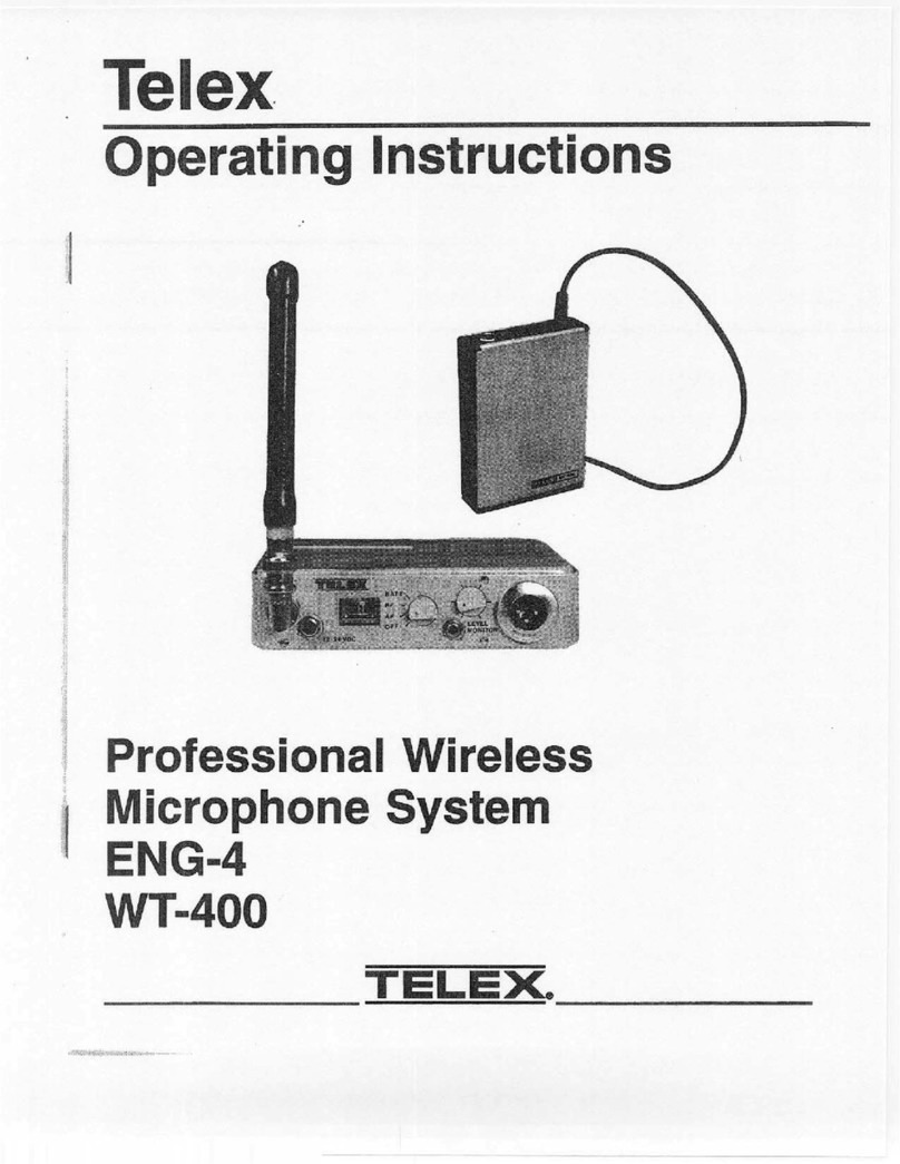
Telex ENG-4 User manual

=
Telex
Operating
Instructions
Professional
Wireless
Microphone
System
ENG-4
WT-400
TELEX.

INTRODUCTION
WHAT
IS
A
WIRELESS
MICROPHONE
SYSTEM?
Microphone:
This
is
an
electro-acoustic
transducer
which
responds
to
sound
waves
and
deliver
essentially
equivalent
electrical
waves.
These
electrical
waves
are
sent
to
the
belt
transmitter
or
handheld
unit.
Transmitter:
The
transmitter
generates
and
amplifies
an
RF
(Radio
Frequency)
carrier
signal,
modulates
this
carrier
with
the
microphone
signal,
and
radiates
the
modu-
lated
RF
carrier.
SIGNAL
MICROPHONE
TRANSMITTER
Figu
RF
CARRIER
Receiver:
The
FM
VHF
receiver
is
tuned
to
the
frequency
of
the
transmitter.
The
receiver
picks
up
the
radiated
RF
signal
from
the
transmitter
through
the
antenna
and
converts
the
RF
signal
into
audio
vol-
tages
for
use
with
PA,
Line,
Network,
etc.
The
receiver
frequency
must
be
matched
to
the
transmitter
frequency.
(CUSTOMER
SUPPLIED)
ae
eae
eS
|
|
AUDIO
|
MIXER
|
SPEAKER
|
|
LAMPLIFIER
|
|
i
|
|
|
|
FM
RECEIVER
are
|
rel
Block
Diagram
of
Typical
Wireless
Microphone
System
WHAT
FREQUENCY
BAND
DOES
THE
TELEX
SYSTEM
OPERATE
IN?
The
Telex
ENG-4
System
features
dual
channel,
crystal
controlled
transmitters
and
four
channel
receivers
operating
in
the
VHF
Band
between
150-216
MHz.
There
are
10
standard
frequencies
available.
Your
system
operates
on
a
fixed
frequency
which
can
be
computer
selected
to
provide
"interference
free"
operation.
Up
to
seven
systems
can
be
operated
in
a
single
location
simultaneously,
without
intermodulation.

OFTEN
ASKED
QUESTIONS
Question:
Can
more
than
one
microphone
be
used
simultaneously?
ae
Yes,
but
never
on
the
same
fre-
quency.
You
will
need
to
have
different
fre-
quencies
for
every
receiver/transmitter
combination.
All
units
are
factory
set
for
specific
frequencies.
Ohoestion:
Is
the
system
more
sensitive
in
any
one
particular
direction?
Aga
No,
the
transmitter’s
antenna
radiates
equally
in
all
directions,
but
the
sig-
nal
is
attenuated
by
your
body,
walls
or
other
surrounding
objects.
The
receiving
an-
tenna
is
essentially
sensitive
in
all
directions
as
well,
except
when
using
a
directional
an-
tenna.
Kestim:
Can
the
receiver
receive
other
transmissions
when
the
transmitter
is
turned
off?
Ay
Yes
it
can.
The
Telex
ENG-4
sys-
tem
operates
in
VHF
band
between
150-
216
MHz.
However,
it
is
not
susceptible
to
radio
wave
skip,
CB’ers
or
standard
FM
radio
transmissions.
29.
The
frequency
on
which
your
system
operates
can
be
computer
selected
for
least
interference,
but
there
is
no
such
thing
as
a
100%
clear
channel
all
the time,
anywhere
in
the
U.S.A.,
forever!
If
the
system
is
going
to
be
used
in
a
per-
manent
fixed
location,
the
system
should
operate
interference
free
until
such
a
time
or
date
when
someone
else
begins
using
the
same
frequency.
If
the
system
is
going
to
be
moving
among
various
locations,
you
will
inevitably
run
into
occasional
frequency
conflicts.
In
either
case,
when
you’re
not
using
the
wireless
microphone,
turn
the
gain
down
on
your
audio
mixer,
just
as
you
would
a
wired
microphone.
If
a
mixer
control
is
not
avail-
able,
turn
the
receiver
off
when
the
trans-
mitter
is
not
in
use.
This
will
prevent
the
reception
of
undesired
signals.
If
a
mixer
control
is
not
available
and
the
system
must
be
left
on,
the
transmitter
should
be
left
on
to
prevent
the
receiver
from
picking
up
outside
interference.

ENG-4
TECHNICAL
INFORMATION
General
Description:
A
fully
transportable
Features:
Small
size,
light
weight
and
is
self
VHF
FM
receiver
ideally
suited
for
electronic
contained.
news
gathering,
film
or
sound
recording,
or
other
such
activities.
Controls
and
Connections
(Front
Panel):
Rotary
Function
Switch/Meter
................ecceeeeeeenes
4-position
rotary
switch
with
meter.
Position
“OPE
ore
cone
came
recto
ce
mero
ese
Non-functional,
no
current
drain.
SHEE
EE
Ll
EE
T
eked
eiaponce
nie
paceuatoate
toveseansieeee
Built
in
meter
monitors
audio
output.
PG
SETTER
pean
ore
r
n
E
vant
Savon
atore
E
A
A
tency
ons
Built
in
meter
monitors
RF
received.
Position
-BAT
Pisses
estas
ve
paws
suienes
nacre
Built
in
meter
monitors
battery
voltage.
SVE
MOTILO
zeant
ENEN
ANEO
E
AIEEE
Adjusts
volume
to
headphone
output
jack.
Antenna
dack:
ausecsai
asas
BNC
jack
(supplied
with
flexible
antenna
for
frequencies
installed).
PQS
VDO
JACE
rea
TEE
ET
EE
EEE
T
NEEE
EAN
E
ONTAS
For
external
power
input.
Accepts
9
to
28
VDC,
center
pin
is
positive.
RER
Connector
wii
smorord
enva
For
MIC
or
LINE
level
output
(selectable
via
MIC/LINE
Switch).
Line
Output:
-ese
tni
esas
EE
A
E
a
E
EEE
For
600
ohm
balanced
line
output.
Mic
Level
Output
200
ohm
balanced
mic
level
output
(adjustable
via
Mic
Level
Control).
Controls
(Rear
Panel):
EERE
N
T
E
N
OREN
E
E
EE
O.
Controls
mic
level
output
to
front
panel
XLR
Connector.
Screwdriver
adjustable,
rotary
type
ENED)
MIC
SWI
areen
CENNAIS
Slide
switch
that
selects
LINE
or
MIC
level
output
for
front
panel
XLR
connector.
Screwdriver
adjustable.
Compandor
IN/OUT
esr
eaey
E
ea
Slide
switch
that
controls
compandor
operation.
Must
be
set
to
match
transmitter
operation.
Screwdriver
adjustable.
Channel
A/B/C/D
i
reireroiuscirecaianin
RF
Channel
(operating
frequency)
selection.
Must
be
set
to
match
transmitter
channel
or
frequency.
Screwdriver
adjustable,
rotary
type.
Battery,
Relegem
ori
iE
eNi
atic
rA
DE
EA
EATE
Squeeze
to
release
slide
locks.
Internal
battery
holder
pops
up
through
top
of
case.
ENG-4
Specifications:
ES
e
VAE
EE
iat
E
E
T
E
P
OER
T
E
E
r
EO
E
Single
conversion
superheterodyne.
THERE
TIS
TU
y
RANEE
ins
cic
cinco
r
a
ws
a a
A
E
e
EA
A
renee
A
ARS
150-216
MHz
Any
1
of
4
frequencies
selectable
by
external
switch.
0.005%
crystal
stability.
WET
o
a
aD
AAN
TERA
Frequency
modulation,
12
kHz.
Nominal
50
uS
de-emphasis.
EE
ETOC
UONE
ace
ers
KOEIE
RD
EAEEREN
E
EREA
O
ENERE
EAS
10.7
MHz.
ER
Sec
Vit)
serora
r
Ere
E
ANEN
NENNEN
9-pole
filter,
150
kHz
wide,
-6
dB/370
kHz
wide,
-60
dB.
aake
rin
WEE
E
r
A
r
N
E
A
A
N
1.0
uV
or
less/0.5
aV
typical
for
12
db
SINAD.
MMB
ge
REjSChOny
anea
oumas
S
Eo
ENEN
AANE
ASEE
ARESE
ERENER
IN
IA
AOT
RON
ENANS
90
dB.
Spur
OuS
KOJEC
OE
e
E
SETE
AS
ESETE
A
GREE
RTSO
E
AERA
EEEE
EEE
EEA
70
dB.
SiON
SL
to
NOBe-
RANO
sones
y
oA
NIEREN
ASEE
EATE
EA
ars,
E
lala
aE
EEEE
ES
(ultimate),
Commn
a
ndore
ao
Mey
KE
ATAA
IE
ETE
EA
ERNE
EAE
NE
ar
104
dB.
Uncompandored:
ceases
an
aH
Ses
OTS
a
GSO
CUED
BO
AE
TE
68
dB.
Seqwuelch
Threshold
ec
ois
ovine,
snn
nA
NMA
EONA
RINE
Nea
aNS
see
eess
Internal,
set
at
1.0
nV.
Suet
ct
tol
oN
279
Uc]
SE
tT
A
Mee
ep
T
PRR
SE
Sc
Rh
Ue
cE
eo
era)
els
aed
sa ce
tt
A
Sa
ee
S
100
dB.
ERATE
oA
R A
oT
aes
de
edna
S
ip
aes
RMP:
A
EIN
fbn
cit
EEO
Rc]
(ultimate)
Ref:
12
kHz
deviation,
104
dB.
PA
ERR
ET
IPO
UN
pycee
eg
eaan
oa
Ges
oe
ae
a
ae
Ref:
12
kHz
deviation,
164
dB.
ARN
OTO
PPI
SUOLTION
crcrsyae
garcia
asus
panniers
OERA
A
OA
1%
or
Less.
0.5%
typical
at
full
output
(1
kHz).

Audio
Fregneney
RESPONSO
cris
araea
Ean
EEA
ane
+1
dB,
100-15000Hz.
Headphone
Onteat
Jack
Power
6
cscs
cs
caesie's
nies
ipese
rosaman
da
EAEN
E
EE
aea
1
kHz
350
mW
(8
ohm
load)
200
mW
(16
ohm
load)
100
mW
(32
ohm
load)
Line
Eevee
l
OUE
oicso:2.3eccainressssjarem
sarna
eies
+14
dBm
Maximum
(12
kHz
deviation).
Mic
Level
Quitas
eso
eeni
EE
EEE
OE
E
e
Ea
aaa
ee
Adjustable,
-7
dB
Maximum
(200
ohms),
(12
kHz
deviation)
-21
dB
Minimum
(200
ohm),
(12
kHz
deviation)
Battery
u
ov
csin's
soss
pa
ose
eete
Four
AA
alkaline
or
nickel-cadmium
required
for
interne!
use.
WT-400
TECHNICAL
INFORMATION
General
Description:
A
belt
worn
battery
Features:
Small
size,
lightweight
and
is
self-
powered
VHF
FM
Transmitter
ideally
contained.
suited
for
any
activity
requiring
a
cordless
portable
microphone.
Controls
and
Connections
(Front
Panel):
Power
OFF/ON
Switch
..........
Low
profile
slide
switch,
allows
access
to
power
OFF/ON.
Microphone
Gain
Control
........s.ssess.
Screwdriver
adjust
for
microphone
gain
control.
Frequency
SWE
ason
annaa
Slide
switch,
choose
either
channel
A
or
B
Frequency.
Microphone
Connect
vs.
iia
eine
nea
eases
eE
EEEa
mere
4-pin
LEMO
connector.
PGND
iren
59:56
5
WERT
ES
ROCEPRNEB
EES
OERE
Permanent,
strain
relief,
flexible
wire
type.
Controls
and
Connections
(Internal):
Compandor
INJOUT
Swieb
ii
<asxdnastsessniaevndemwgueay
aaa
ven
Ea
Slide
switch.
AHEDBR
os
ie
shin
9005
Wa
sisia's
Flexible
wire
type,
permanently
attached
to
the
front
panel
(top)
Battery
Compartment
.
......<000cccseces
For
9
volt
alkaline,
Mallory
MN1606
or
equivalent.
Average
life
is
6-8
hours
minimum.
Battery
Tests:
sess
sisi
A
red
LED
is
mounted
on
the
front
panel.
A
fresh
battery
will
cause
the
LED
to
flash
one
time
when
the
transmitter
is
turned
on.
A
week
battery
will
illuminate
the
LED
constantly.
A
dead
or
unusable
battery
will
show
no
indication.
WT-400
Specifications:
TIPE
ies
ho
gS
is
ees
ee
TR
Ea
THAD
ONES
Es
CEN
E
Direct
FM,
x
9
multiplication.
FROGUERCY
RADE
6,000
0-0
rona
aee
150-216
MHz
(one
of
two
frequencies
selectable
from
front
panel
switch,
A
or
B)
/0.005%
crystal
stability.
RE
POMS
RIOT
ai
gis
a
in
Paine
BA
ESOC
E
eRe
ee
SS
50
mW
maximum,
45
mW
typical.
MOHOR
cn.
en
ae
sacked
>
EA
are
Maw
AORERE.
Frequency
Modulated,
12
kHz
deviation
Nominal
50
„S
pre-emphasis.
Microphone
Input
.............
100-10k
ohm
dynamic,
or
electret
(+5
volts
bias
available).
Microphone
Gain..........
Screw
driver
adjustable.
0.007
V
RMS
input
required
for
100%
modulation.
1.0
V
RMS
maximum
acceptable
input.
MOTtaan
On
LAO
S
ooa
be
es
ATE
ES
eo
Internal
Compressor
(Compandor
System).
DRY
oara
EREE
SEENA
EAE
Senses
LNE
aN
EES
E
ES
AEG
9.0
Volts
nominal.
Current
Grant
aeo
56cm
t's
coends
E
ae
Keach
sence
eraRuNomees
cases
40
mA
typical

ENG-4
CONTROLS
AND
CONNECTIONS
27049-A-003
ROTARY
FUNCTION
SWITCH/
METER
DISPLAY-
RF
~
ARE
5
OFF
7
#28
VOC
FOR
EXT
OC
—
REMOVE
BATT
1
|
XLR
RECEPTICAL
(Output
to
Audio
yata
i
l
EXTERNAL
|
LLEVEL
MONITOR
POWER
JACK
|
CONTROL
EARPHONE
JACE
ames
BATTERY
PACK
Figure
2
`
Front
Panel
—
ENG-4
Antenna
Jack:
BNC
type
receptical,
Refer
to
Antenna
Connection,
Page
9
and
Figure
9.
External
Power
Jack:
For
external
power
source,
9
VDC
to
28
VDC/100
mA.
Refer
to
Figure
7.
Rotary
Function
Switch/Meter
Display:
ROTARY
FUNCTION
SWITCH
-
4-position
switch:
=
OFF
Position
-
Non
Functional
-
no
current
drain.
AF
Position
-
Indicates
relative
modulation
of
the
system
(Audio
Output).
RF
Position
-
Indicates
when
the
ENG-4
is
receiving
a
transmitter
signal
(Carrier
Indicator).
Indication
is
relative
only.
Red
bar
normally
indicates
weaker
RF
Signal,
Green
bar
normally
indicates
stronger
RF
Signal.
BATT
Position
-
The
meter
indicates
the
relative
battery
condition.
Red
bar
indicates
weak
or
marginal
batteries,
Green
bar
indicates
good
batteries.
5-
METER
DISPLAY
-
A
tri-color
meter,
relative
indication
of
Audio
Output
(AF),
received
signal
(RF),
or
battery
condition.
Selectable
via
the
Rotary
Function
Switch.
Earphone
Jack:
Connect
to
supplied
earphone
for
monitoring
incoming
audio
from
transmitter’s
microphone.
Level
Monitor
Control:
Adjusts
volume
to
earphone
output
jack.
DOES
NOT
AFFECT
MIC
OR
LINE
LEVEL.
XLR
Receptical:
Output
to
audio
sound
system
(Amplifier/Mixer,
Video-Cam,
etc.).
Output
is
adjust-
able
for
MIC
Output
by
means
of
the
MIC
Level
Control.
MIC/LINE
Switch
must
be
in
the
“MIC”
position
to
be
adjustable.
Refer
to
Receiver
Output
Connection,
pages
9
and
10.

MIC
LEVEL
CONTROL
|
E
|
|
|
|
EEN
MIC
fever
;
Faa
@=.
.
COMPANDOR
LINE
[Ty
ic
IN
I]
Out
D
|
|
LINE/MIC
SWITCH
|
|
|
COMPANDOR
IN/OUT
SWITCH
CHANNEL
SELECTOR
27049-
A-004
L-4
L
BATTERY
RELEASE
BATTERY
HOLDER
“POPS
UP”
Figure
3
Rear
Panel
—
ENG-4
MIC
Level
Control:
Rotary,
screwdriver
adjustable
control
which
controls
MIC
Level
Output
to
the
front
panel
XLR
receptical
when
selected
by
LINE/MIC
Switch.
(200
ohm
balanced
MIC
Level
Output).
LINE/MIC
Switch:
A
slide
switch
that
selects
LINE
or
MIC
level
output
for
front
panel
XLR
receptical.
Use
supplied
plastic
screwdriver
to
operate
slide
switch
to
desired
position.
Compandor
IN/OUT
Switch:
A
recessed
slide
switch
that
controls
compandor
operation.
Must
be
set
to
match
transmitter
operation.
Use
supplied
plastic
screwdriver
to
slide
switch
to
desired
position.
Channel
Selector:
Choice
of
4
separate
RF
channels
(operating
frequency).
Must
be
set
to
match
transmitter
channel
or
frequency.
Screwdriver
adjustable.
Battery
Release:
Squeeze
to
release
slide
locks.
Internal
battery
holder
pops
up
through
top
of
case.

WT-400
CONTROLS
AND
CONNECTIONS
LOW
BATTERY
ada
el
LED
TRAILING
WIRE
ANTENNA
|
MICROPHONE
JACK--—.
OFF/ON
SWITCH
|
N
|
D
Telex
WLM-200
or
Equivalent
ADAPTOR
CABLE
-
Connect
to
any
Impedance
Microphone
(100-10k
ohm)
|
{
(NOT
SUPPLIED)
MICROPHONE
--+
&-CHANNEL
SELECTOR
GAIN
CONTROL
(Frequency
Switch)
Figure
4
Top
Panel
—
WT-400
BATTERY
COMPARTMENT
RELEASE
BATTERY
4
COMPANDOR
/
IN/OUT
SWITCH
—
——\
"in"
&
w
"ouT"
Figure
5
Internal
View
—
WT-400
Microphone
Jack:
The
WT-400
was
designed
to
Trailing
Wire
Antenna:
A
fully
flexible
14-wave
easily
interface
with
dynamic
or
electret
antenna
with
a
permanent
strain
relief.
microphones
in
the
100-10k
ohm
impedance
range.
A
‘
(10k
ohm)
resistor
is
permanently
wired
to
the
audio
Microphone
Gain
Control:
Screwdriver
circuit
to
provide
a
source
for
electret
microphones.
adjustable.
Adjusts
the
Audio
Gain
of
the
No
XLR
adaptor
cable
is
provided
with
this
system.
microphone
either
up
or
down.
baea
hned
ie
galee
the
Pae
WOMI
Channel
Selector
(Frequency
Switch):
A
slide
switch
which
allows
the
user
to
select
either
Channel
OFF/ON
Switch:
A
low
profile
slide
switch
is
A
or
B
frequency.
Screwdriver
adjustable.
ided
to
all
OFF
:
a
ACCHA
SOPOTE
AAN
Battery
Compartment
Release:
Depressing
the
Low
Battery
Indicator
LED:
Fart
of
the
battery
two
side
spring
latches
and
pulling
the
bottom
of
the
check
circuit.
When
the
power
switch
is
placed
in
the
case
downward
exposes
the
battery
compartment.
“ON”
position
the
LED
will
flash
one
time
if
the
r
:
battery
is
good.
A
poor
battery
will
cause
the
LED
to
Compandor
IN/OUT
Switch:
Internal
switch
be
illuminated
continuously
and
a
bad
or
unusable
allows
the
user
to
control
the
WT-400
compandor
battery
will
not
cause
any
illumination
at
all.
operation.
Must
be
set
to
match
receiver
operation.
oe

FOR
LINE
LEVEL
CONNECTION
(Less
Common):
This
connection
is
identical
to
MIC
LEVEL
connection
with
the
following
exceptions:
Place
the
output
level
switch
in
the
LINE
position.
A
2-conductor
phone
plug
will
be
needed
on
the
Mixer/Amplifier
end
of
the
audio
cable
to
connect
to
the
%
inch
line
input
jack.
See
Figure
11.
After
you
have
selected
either
MIC
or
LINE
operation,
turn
the
Monitor
Level
Control
down
(counterclockwise)
and
attach
a
monitor
earphone,
if
desired.
Adjust
listening
level
to
suit.
NOTE:
MIC
output
is
200
ohms,
adjustable
level
via
the
MIC
LEVEL
Control.
LINE
output
is
600
ohms,
fixed
level.
Set
the
Channel
Selector
Switch
to
match
the
transmitter.
27049-A-013
TO
AMPLIFIER
“Nxir
CONNECTOR
(CABLE
NOT
SUPPLIED)
STANDARD
XLR
TYPE
CONNECTIONS
|
=
GROUND
(COMMON)
2
=
AUDIO
[IN
=
PHASE}
3
—
AUDIO
(OUT-OF
-PHASE
)
Figure
11
“LINE
LEVEL”
Connection
TRANSMITTER
SET-UP
AND
CONNECTIONS
Battery
Installation:
Insure
that
the
power
switch
is
in
the
“OFF”
position.
Depress
the
two
spring
latches
(See
Figure
12)
on
each
side
of
the
case.
Pull
the
front
panel
assembly
forward
until
the
transmitter
is
removed
from
the
case.
Insert
the
battery
as
shown
in
Figure
12,
making
sure
the
proper
polarity
is
observed.
27049-A-005
DEPRESS
BOTH
BATTERY
COMPARTMENT
RELEASES
WHILE
PULLING
ON
THE
BASE
,
TO
REVEAL
THE
BATTERY
COMPARTMENT.
BATTERY
Figure
12
CompandorIN/OUT:
Determine
whether
it
is
desired
to
operate
with
the
compandor
IN
or
OUT.
Basically,
this
is
a
personal
choice.
Some
operators
prefer
to
operate
with
the
compandor
OUT,
even
at
the
expense
of
signal-to-noise
ratio
and
other
advantages
of
compandor
operation.
In
any
case
place
the
internal
compandor
switch
(See
Figure
5)
to
the
“IN”
or
“QUT”
position,
as
desired.
NOTE:Double
check
to
be
sure
that
the
receiver
compandor
switch
is
in
the
same
position
as
the
transmitter,
either
IN
or
OUT.
Microphone
Connection:
Reinsert
the
transmitter
into
the
case
until
the
latches
are
secure.
Plug
the
microphone
into
the
transmitter.
Refer
to
Figure
13.
(If
the
microphone
brand
that
you
are
using
is
other
than
Telex,
request
“Technical
Bulletin
No.
PA-
84-1”
for
interface
information.
Using
the
screwdriver
provided,
set
the
Frequency
Switch
to
A
or
B,
to
match
the
receiver.

Battery
Check:
Set
the
power
switch
to
the
“ON”
position.
Note
that
the
battery
LED
gh
i
ici
a
5
(labeled
LOW)
should
flash
one
time
on
a
good
1
=
SHIELD
27049-A-
010
battery.
A
poor
battery
will
cause
the
LED
to
be
1o
PEREIS
illuminated
continuously
and
a
bad
or
unusable
4-
NC.
a
er
eens
battery
will
not
cause
any
illumination
at
all.
Set
the
power
Switch
to
the
“OFF”
position.
Refer
to
Figure
4.
Assuming
that
you
have
set-up
the
receiver
previously,
proceed
to
the
“Setting
System
Gain
Levels”
section.
Figure
13
Microphone
Connection
SETTING
SYSTEM
GAIN
LEVELS
Introduction:
If
you
have
followed
the
Transmitter
Gain
Setting:
instructions
up
to
this
point
you
should
now
be
STEP
1
ready
a
set
optimum
signal
gain
settings
on
Turn
the
ENG-4
receiver
Function
Switch
to
the
each
unit.
ryan
an
RF”
position.
Set the
WT-400
power
switch
to
the
“ON”
position.
The
ENG-4
meter
should
indicate
in
the
“GREEN”
area.
Turn
the
ENG-4
Function
Switch
to
the
“AF”
position.
See
Figure
14.
27049-A-009
pe
-
ENG-4
FUNCTION
SWITCH
TO
"RF"
POSITION
3-ENG-4
METER,
NEEDLE
IN
GREEN
BAND
4
-FUNCTION
SWITCH
TO
"AF"
POSITION
{URI
LPT
(CONTINUE
TO
NEXT
STEP)
Figure
14
Checking
Incoming
RF
Signal
Abts

STEP
2
The
microphone
“GAIN”
Control
on
your
WT-
400
has
been.factory
set
for
normal
or
average
audio
levels.
High
Level
Setting:
If
your
application
is
in
a
high
SPL
(Sound
Pressure
Level)
area
such
as
singing
or
instrumentation,
the
factory
gain
setting
is
probably
too
high
and
will
result
in
overload
or
distortion.
This
will
be
indicated
on
the
ENG-4
receiver
meter
between
0
to
+3
(red).
Low
Level
Setting:
If
your
application
is
in
alow
SPL
area,
the
factory
gain
setting
is
probably
to
low.
This
will
beindicated
by
low
meter
indication
on
the
ENG-4
meter,
-20
or
below
(white).
To
correct
either
a
too
high
or
too
low
setting,
adjust
the
Microphone
Gain
Control
(screw-
driver
slot)
on
the
front
panel
of
the
WT-400,
so
that
average
audio
causes
the
meter
to
indicate
between
-20
to
-5.
An
occasional
overshoot
into
the
RED
area
is
allowable.
Refer
to
Figure
15.
27049-A-008
(METER
—
FRONT
PANEL
OF
ENG-4)
TOO
HIGH
TOO
LOW
CCW
—
TURNS
CW
—
TURNS
AUDIO
GAIN
AUDIO
GAIN
DOWN
UP
Figure
15
High
Level
and
Low
Level
Gain
Adjustment
-12-
Receiver
Gain
Setting:
After
the
trans
mitter
gain
has
been
properly
set,
you
are
nov
ready
to
set
receiver
gain.
NOTE:
Insure
that
the
Compandor
IN/OU™
switch
on
the
receiver
agrees
with
the
trans
mitter
Compandor
IN/OUT
Switch.
Set
the
LINE/MIC
Switch
as
required.
In
th.
LINE
position,
thereis
no
adjustment.
The
Lin:
output
level
is
fixed.
In
the
MIC
position,
th:
output
level
is
adjustable
via
the
MIC
Leve
Control
(screwdriver
slot).
Refer
to
Figure
3.
Adjust
the
level
to
accomodate
the
mixer
o:
other
audio
system.
NOTE:
This
control
does
not
affect
the
ENG
4
meter
indication.
If
monitoring
is
required,
plug
the
earphone
(supplied)
into
the
Monitor
Jack
on
the
front
o:
the
ENG-4
receiver
and
adjust
the
Monito:
Level
Control
for
comfortable
listening
Adjusting
the
Monitor
Level
DOES
NOT
affec
the
MIC
LEVEL.
They
are
independent
functions.
Refer
to
Figure
2.

SYSTEM
WALK-THRU
General:
Now
that
you
have
successfully
“set
up”
your
Telex
Wireless
System
and
turned
on
your
sound
equipment
(amplifier/mixer,
video
cam
etc.),
you
are
ready
to
test
the
overall
performance
by
“Walking”
the
Telex
transmitter
through
the
areas
in
which
you
will
be
using
it.
.
The
“system
walk-thru”
can
detect
the
following
RF
problems:
Weak
signal
strength
caused
by:
1.
Poor
antenna
location
2.
RF
“Trouble
Spots”
3.
Operating
distance
beyond
System
capability
4,
Malfunctioning
system
Carrier
Indication:
Under
normal
condi-
tions
with
the
Rotary
Function
Switch
in
the
“RF”
position
the
carrier
indication
on
the
meter
should
always
be
center
scale
or
higher
(green
area)
with
the
transmitter
“ON”.
See
Figure
14.
“Weak
Signal”
conditions
will
result
in
low
meter
indication
with
the
potential
of
actually
“hearing”
this
in
the
sound
system.
Audio
Feedback:
The
system
walk-thru
can
also
uncover
locations
in
the
performing
area
which
are
prone
to
audio
feedback
(usually
sounds
like
a
“squeal”
or
a
“howl”).
Feedback
can
be
a
problem
for
any
microphone
—
whether
wired
or
wireless.
To
eliminate
feedback
observe
placement
of
the
microphone
and
any
nearby
loudspeakers.
i
In
99%
of
allinstances
you
will
set
up
your
Telex
Wireless
System,
walk
it
through
and
achieve
`
error-free
performance.
If
in
the
rare
instances
your
Telex
System
does
not
“pass”
during
your
walk-thru
evaluation,
refer
to
the
last
two
sections
of
this
manual
which
deal
with
Antenna
Information
and
System
Trouble-
shooting.
TROUBLESHOOTING
Reread
the
sections
of
this
manual
to
make
sure
you
have
completed
system
set-up
properly.
PROBLEM
SOLUTION
DISTORTION
—
System’s
audio
quality
seems
distorted
at
medium
to
high
input
levels.
HISS
—
System
seems
to
produce
a
“hiss”
which
is
undesirable.
LOW
OUTPUT
—
System
produces
a
lower
output
level
than
wired
microphone
in
sound
system.
Reduce
audio
gain
on
the
transmitter
by
ad-
justing
gain
control
as
suggested
on
Pages
11
and
12.
Check
the
gain
settings
on
both
the
transmit-
ter
and
receiver
as
indicated
on
Pages
11
and
12,
they
may
be
too
low.
Check
Compandor
IN/OUT
Switch.
Check
the
gain
settings
on
both
the
transmit-
ter
and
receiver
as
indicated
on
Pages
11
and
12,
they
may
be
too
low.

TROUBLESHOOTING
CONT.
PROBLEM
SOLUTION
FEEDBACK
—
Moving
around
performing
area
produces
“squeal”
or
“howl”
in
various
locations.
DROPOUTS
—
When
moving
around
per-
forming
area
there
seem
to
be
locations
where
the
signal
‘“‘swooshes”
or
completely
disappears.
INTERFERENCE
—
System
picks
up
signals
other
than
wireless
transmitter.
REDUCED
DISTANCE
—
System
doesn’t
operate
as
far
as
it
once
did.
System
doesn’t
operate
as
well
as
you
think
it
should.
BATTERIES
DON’T
LAST
(TRANSMITTER)
BATTERIES
DON’T
LAST
(RECEIVER)
If
you
are
unable
to
solve
the
problem
contact
the
dealer
from
whom
you
purchased
the
system
for
assistance.
Reduce
gain
settings
on
wireléss
system
and
sound
system.
Readjust
nearby
loud-
speakers.
Make
sure
the
antenna
is
connected
and
fol-
low
the
location
suggestions
on
Pages
16
and
17.
Change
the
location
of
the
receiver/
antenna
or
avoid
the
bad
area
with
the
transmitter.
Make
sure
Telex
transmitter
is
turned
on
—
this
will
usually
eliminate
the
interfering
signal.
If
problems
persist
with
Telex
transmitter
on,
you
will
probably
need
to
have
your
system’s
frequency
changed
to
another
channel.
Transmitter
battery
is
possibly
in
need
of
replacement.
Receiver
antenna
possibly
located
incorrectly.
See
Pages
16
and
17
for
proper
placement.
If
using
“throw
away”
batteries,
make
sure
they
are
alkaline
(Mallory
MN1604
or
equivalent).
If
using
nickel-cadmium,
make
sure
it
is
an
8.4
volt,
7.2
volt
batteries
won't
work. Refer
to
Page
15.
If
using
“throw
away”
batteries,
make
sure
they
are
AA
alkaline
(Mallory
MN1500)
or
equivalent.
1
4-

BATTERY
INFORMATION
-
General:
Improper
battery
selection,
use,
in-
stallation
and
care
are
the
cause
of
numerous
wireless
system
failures.
Alkaline
Batteries:
Alkaline
batteries
such
as
Mallory’ss
DURACELL®
or
Eveready’s
ENERGIZER®
provide
the
most
reliable
operation
in
wireless
transmitters.
The
use
of
low
cost
carbon-zinc
batteries
is
NOT
recommended.
Nickel-Cadmium
Batteries:
These
batteries
can
save
you
money
in
the
long
run,
as
they
can
be
recharged,
but
they
can
also
cause
disappointing
wireless
performance.
If
you
want
to
use
rechargeable
nickel-cadmium
batteries
you
must
select
a
heavy
duty
nickel-
cadmium.
Conventional
9
volt
sizesuch
as
GH®
or
Radio
Shack®
are
only
capable
of
providing
7.2
volts,
which
is
not
sufficient
to
power
the
Telex
WT-400
transmitter.
Nickel-Cadmium
Memory
Effect:
For
maximum
performance
and
longer
life
from
nickel-cadmium
batteries
you
should
completely
discharge
them
whenever
possible.
This
can
be
done
by
simply
leaving
the
Telex
transmitter
turned
on
overnight.
If
nickel-
cadmiums
are
not
discharged
on
aregular
basis
they
will
remember
how
long
you
use
them
for
each
performance
and
will
not
have
the
ability
to
retain
their
original
performance.
ENERGIZER®
is
a
registered
trademark
of
Union
Carbide
Corporation.
DURACELL®
is
a
registered
trademark
of
Duracell
Inc.
-15-
Tapoca
Tie
Conventional
“RAY-O-VAC”
Not
Carbon
Zinc
Recommended
Does
Not
Work
1%
to
2
Hours
per
charge
Alkaline
“MALLORY”
MN1604
or
Equivalent
GE
or
Radio
Shack
Nickel-
Cadmium
Rechargeable
Varta
or
Gould
“Again
and
Again”
Nickel-Cadmium
Rechargeable
Table
1
Battery
Information
for
WT-400
Oe
RE
6-8
Hours
Alkaline
“EVEREADY”
#E91
or
Equivalent.
EVEREADY
Nickel-Cadmium
#CH15
or
Equivalent
45
Hours
Table
2
Battery
Information
for
ENG-4
GE®
is
a
registered
trademark
of
General
Electric
Company
Radio
Shack®
is
a
registered
trademark
of
the
Tandy
Corp.
SROH
HHIHHIHHII

———
RES
nr
ES
SPREE
PD
SE
tS
ANTENNA
INFORMATION
Antenna
Alignment:
To
align
the
antenna
properly
refer
to
Figure
16.
27049-8-
O16
Figure
16
Antenna
Alignment
Do
and
Don’t
Antenna
Polarization:
The
Telex
Wireless
System
is
“Vertically
Polarized”.
This
means
both
the
transmitting
and
receiving
antennas
should
operate
in
the
vertical
position.
27049-A-O17
RECEIVER
ANTENNA
TRANSMITTER
me
Figure
17
Vertically
Polarized
Antenna
Antenna
Placement:
Keep
the
distance
between
the
transmitter
and
the
receiver's
antenna
as
short
as
possible.
The
greater
the
distance,
the
weaker
the
signal.
27049
-B-024
/
/
/
/
Figure
18
Distance
Between
Transmitter
and
Receiver
Make
sure
the
“signal
path”
between
the
transmitter
and
receiver’s
antenna
is
unobstructed.
You
should
always
be
able
to
visibly
locate
the
antenna
at
all
times.
2704
-4-0r8
Figure
19
Keeping
Site
Clear
to
Antenna

|?
à)
$?
E:
Attempting
to
operate
the
wireless
system
27049-8-021
through
or
around
walls,
ceilings,
metal
objects,
etc.,
will
reduce
system
range
and
performance.
27049-B-020
WALLS,
CEILING,
METALLIC
OBJECTS,
ETC.
CAN
SIGNAL
REFLECTION
OFF
A
METAL
OBSTRUCTION
De
r
PRA
>
CAUSES
REDUCED
SIGNAL
AND
“MULTIPATH”
ene
a
Figure
20
Fi
s
gure
21
Operating
Through
Obstructions
Multipath
Reception
Dropouts/
Picket
Fencing:
A
“signal
dropout”
can
occur
at
any
operating
distance
and
is
caused
by
the
direct
signal
from
the
transmitter
and
reflected
signals
from
the
transmitter
(called
multipath)
arriving
at
the
receiving
antenna
out-of-phase.

FCC
REGULATION
The
Telex.
Model
WT-400
Transmitter
is
Type
Accepted
under
United
States
Federal
Com-
munications
Commission
Parts
90
and
74.
The
receiver
ENG-4
is
Type
Accepted
under
Part
15 of
the
Federal
Communications
Commission.
Licensing
of
Telex
equipment
is
the
user’s
responsibility
and
licensability
depends
upon
the
user’s
classification,
user’s
application,
and
frequency
selected.
Telex
strongly
urges
the
user
to
contact
the
appropriate
telecommunica-
tions
authority
for
any
desired
clarification.
CAUTION:
Changes
or
modifications
made
by
the
user
could
void
the
user’s
authority
to
operate
the
equipment.
eral
ee
aces
lt
bi

ACCESSORIES
Lapel
Microphone
-
Electret
type
comes
with
Nickel-Cadmium
Battery
-
For
WT-400
tie
clip
and
lapel
clip
holder.
Transmitter
8.4
Volts
WLM-100/Order
No.
63852-000
Order
No.
63912-000
WLM-200/Order
No.
63852-001
PH-22
Headworn
Microphone
-
Close
talk-
ing,
noise
cancelling
electret.
Order
No.
64327-002
Carrying
Case
-
For
the
WT-400
Trans-
mitter
Order
No.
59756-000
Adaptor
Cable
-
SLR
to
LEMO
adaptor
cable
for
WT-400
Order
No.
63841-000
Carrying
Case
-
For
the
ENG-4
Receiver
Order
No.
70372-000
27049-A-936
(ee
=
ry
ts
BC-2
Battery
Charger
-
For
charging
nickel-
cadmium
battery
used
in
WT-400.
Order
No.
64267-000
aroas
aore

REPLACEMENT
PARTS
Battery
Sled
Assembly
-
For
ENG-4
Antenna
Replacements
-
For
ENG-4
anc
Receiver.
Replacement
or
for
extra
battery
WT-400.
When
ordering
antenna
order
b:
holder.
the
frequency
of
the
receiver.
Order
No.
64480-000
ENG-4
Replacements
Earphone
Assembly
-
For
ENG-4
for
150-158
MHz/Order
No.
57032-005
monitoring
incoming
audio
from
158-165
MHz/Order
No.
57032-006
transmitter’s
microphone.
Four
separate
165-175
MHz/Order
No.
57032-000
parts.
175-185
MHz/Order
No.
57032-001
Cord,
CMT-98
185-195
MHz/Order
No.
57032-002
Order
No.
60013-015
195-205
MHz/Order
No.
57032-003
B
Eartip,
ET-1
205-216
MHz/Order
No.
57032-004
Order
No.
35608-000
C
Earloop,
AEF-2
WT-400
Replacement
Order
No.
09252-000
150-216
MHz/Order
No.
70277-000
D
Earphone,
RTW-04
Order
No.
60012-005
\
p
CF
For
the
ENG-4
-20-
Other manuals for ENG-4
1
This manual suits for next models
1
Table of contents
Other Telex Microphone System manuals

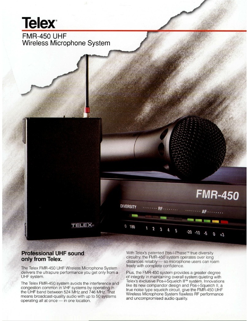
Telex
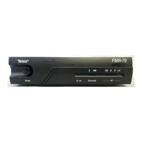
Telex FMR-450 UHF User manual

Telex
Telex SAFE-1000 User manual

Telex
Telex ENG-4 User manual

Telex
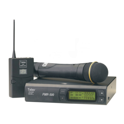
Telex FMR-500 User manual

Telex
Telex FMR-1000 User manual
Telex
Telex PAS-1 User manual

Telex
Telex FMR-10 UHF User manual

Telex
Telex FMR-70 User manual

Telex
Telex FMR-70 User manual

Telex
Telex FMR-500 User manual