LB Pinto 400 V329/8
Best practices were employed in cost engineering throughout the development
of LaserBit
Invisible laser radiation, Class 3B laser product. Looking directly into the
laser beam can cause permanent damage to the eye!
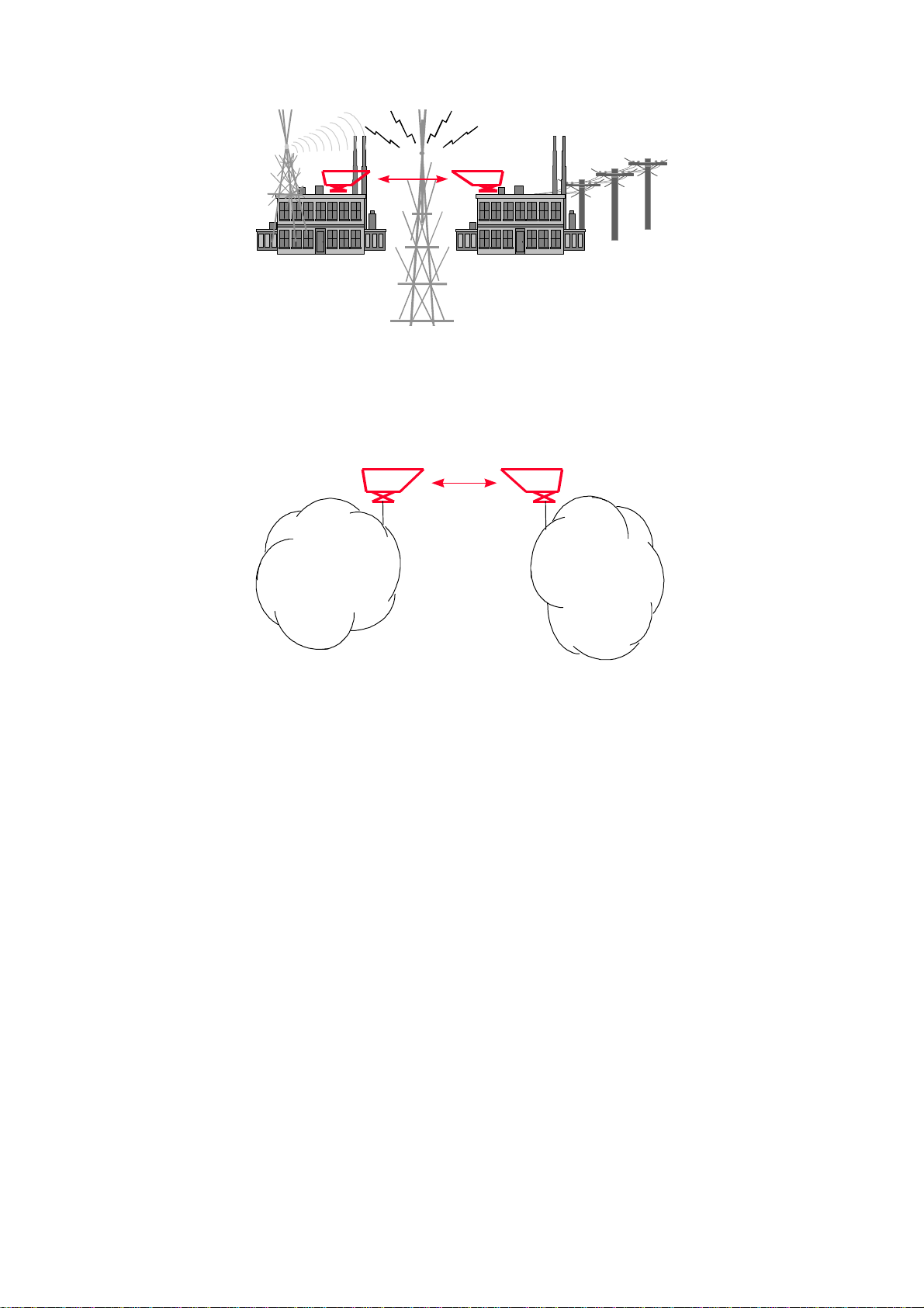
1.1 Optical free space transmission
The principle used in free space laser transmission is very similar to the one is
used for fiber optic transmission. The difference is while fiber optic devices use
electronics and optics optimized for optical fiber, free space communication
equipment deploys electronics and optics optimized for transmission through the
air. Also one can observe the similarity in the transmission properties. No
galvanic contact, no ground loops, no need for surge protection, noise immunity,
long distances, high bandwidth.
What makes it unique –and difficult to design –is that it does not require any
transmission medium like fiber or copper, but has to cope with the dynamically
changing parameters. For instance while the attenuation of an optical fiber is
constant, the attenuation of the atmosphere between the laser units can change
dramatically (depending on the weather conditions).
The LaserBitheads are usually placed on top of buildings, where the clear line
of sight is guaranteed and the beam cannot be interrupted.
In the head the incoming signal is amplified, encoded, then drives the laser
diode. The transmitter optics assures the proper beam shape and controls the
beam divergence. The receiver optics perceives and directs the transmitted
signal to the photodiode. The diode converts it back into electrical, then it is
decoded, amplified and converted.
There are several things that can influence the quality of transmission. We can
classify those factors into three main groups.
?System conditions -transmitting power, transmitter’s wavelength, beam
divergence, receiver optics diameter, receiver sensitivity, parameters of
optical system and casing. These parameters determine the system’s
characteristic at a certain distance and are controlled by system design and
factory set up.
?Weather conditions -molecular absorption, particle scattering and
turbulence. These elements have great effect on the operational conditions
of the system. We do not have very much influence on them; proper
product selection can eliminate the undesirable effects.