Tellabs 6162 User manual

Ytellabs
technical
manual
76-816162
rev A
practice
section
816162/816162A/8161628/816162C
©Tellabs, Inc.,
-I
May 1985
all rights reserved, printed in USA
figure
1.
6162A 4Wire-to-2Wire
SF-to-E&M Terminal
Repeater
module
•Isolation transformers at both facility-side 4wire
ports and
at
the
terminal-side
2wire
port.
•
Independently
switch-selectable
1200
or
600-
ohm
terminating
impedance
at
each
4wire
facil-
ity-side port, and switch-selectable
900
or
600-ohm
terminating
impedance in series with
2.15p.F at
the
terminal-side
2wire
port.
•Integral
compromise
balance
network
(CBN),
with provision for external precision balance
network
(PBN).
•From 0
to
0.030p.F of switch-selectable
network
build-out (NBO)
capacitance
in O.o02p.F
increments.
•Switch-selectable Type
I,
II,
or
III E&M interface.
•Switch-selectable A-side or B-side
E&M
signaling.
•Integral
2600Hz
SF
tone
oscillator.
•Front-panel LED's
that
light
to
indicate local
E-Iead and M-Iead busy.
•Reverse-battery and overvoltage protection.
•
Opening
and monitoring bantam-type jacks
at
all ports (6162 and
6162A
only).
•Local or remote signaling and equal-level trans-
mission
loopback
(6162A
and
6162C
only).
1.05 The
loopback
circuitry on
the
6162A
and
6162C
provides
the
following features:
•Ability
to
remotely perform facility, level, and
equalization transmission tests.
•Ability
to
remotely
test
the following signaling
circuitry:
1)
SF detector.
2)
SF
transmitter
(both
augmented
and normal
levels).
3) Transmit path cut.
4) E&M
detectors
and signaling relay.
5)
Signaling logic.
page
1
page
2
page
5
page
9
page
14
page
10
page
16
table
1.
6162X
module
selection
guide
6162,
6162A,
61628,
and
6162C
4Wire-to-2Wire
SF-to-E&M Terminal Repeaters
~
J.'~
module
front-panel
jacks
loopback
6162
ves
no
6162A
yes yes
61628
no no
6162C
no yes
1.04 All
four
6162X
modules
offer
the
following
features:
•
2wire-to-4wire
conversion via an integral mag-
netic hybrid.
•From 0
to
24dB
of prescription-set gain
or
loss
in both
the
transmit
and
receive
channels
at
the
facility-side ports.
•From 0
to
24dB
of prescription-set loss
in
both
the
transmit
and
receive
channels
at
the
ter-
minal
side
(on
the
4wire
side
of
the
hybrid).
•Prescription receive-channel
amplitude
equal-
ization equivalent
to
that
provided
by
the
Western Electric
309B
Prescription Equalizer.
contents
section
2
general
description
section
2
application
section
3
installation
section
4
circuit
description
section
5
block
diagram
section
6
specifications
section
7
testing
and
troubleshooting
1.
general
description
1.01
The 6162, 6162A,
61628,
and 6162C 4Wire-
to-2Wire SF-to-E&M Terminal Repeaters are Tellabs
Type
10
plug-in
modules
that
provide
both
active
transmission
interface
and
signaling
conversion
between
a
4wire
metallic
facility
that
uses
2600Hz
single-frequency
(SF) signaling
and
a
2wire
PBX
trunk
or
carrier
channel
that
uses
E&M signaling.
All
four
6162X
modules
meet
the
specifications
given in AT&T Technical
Reference
Pub
43002
for
Network
Channel Terminating
Equipment
(NCTE)
Criteria, and, in addition,
the
6162A
and
6162C
meet
the
specifications
given in Pub
43004
for
Transmission and
Signaling
Loopback
Criteria.
1.02 In
the
event
that
this
practice
section
is
reissued,
the
reason
for
reissue will
be
stated
in
this
paragraph. In
those
parts of
this
practice
that
apply
equally
to
the
6162,
6162A,
6162B,
and
6162C, all
four
modules
are, for
convenience,
referred
to
as
the
6162X
module.
1.03 While all
four
6162X
NCTE
modules
share
the
same basic transmission-interface and signaling-
conversion circuitry,
they
differ
through
the
pres-
ence
or
absence
of
loopback
capability
and
of
front-panel jacks. Table 1lists
the
differences
be-
tween
the
four
6162X
modules.
page
1
practice
section
816162/816162A/816162B/816162C
•
Manually
activated
(local)
loopback
via switch
option.
•
Manually
activated (local)
loopback
via
ground
on
the
MLB
lead
or
contact
closure
between
the
MLB
and
MLBG
leads.
•
2713
Hz
tone-activated
(remote)
loopback
with
second-tone
or
automatic
timeout
(see below)
loopback
deactivation.
•
Automatic
deactivation
of
tone
loopback
after
switch-selectable
4-minute
or
20-minute
time
out
interval.
•
From-23
to
+24dB
of
prescription-set
gain (in
switch-selectable
1
dB
increments)
for
true
equal-Ievelloopback.
•
Option
switch
for
busying
out
the
module's ter-
minal side
during
loopback, if desired.
•Front-panel
status-indicating
LED
that
lights
when
the
module
is in loopback.
2.
application
2.01 The
6162X
4Wire-to-2Wire
SF-to-E&M Ter-
minal
Repeater
module
is
typically
used
to
inter-
face a
4wire
SF
transmission
facility
with
a
2wire
E&M
trunk
or
line
associated
with
a
two-way
dial!
supervisory
telephone
circuit.
No
external transmis-
sion
interface
circuitry
is
needed
because
the
6162X
module
combines
the
functions
of
a
4wire-
to-2wire
li~le
amplifier, an SF transceiver, an
SF-to-
r
...
~.LcJl~~~
.•..
·.i-((f~.~.
lW-
;~
I
r:
'<}! }
J+
#:
e"
iJ
-~_~.
__
2!1
Sf
fl'lSBSG
+-
S"~1
III
111'
....
1L
------l-
_
IINl
f
Hf
AU
L...-~
__L
~
_
I I
TL
12M
I
INTEHrAn
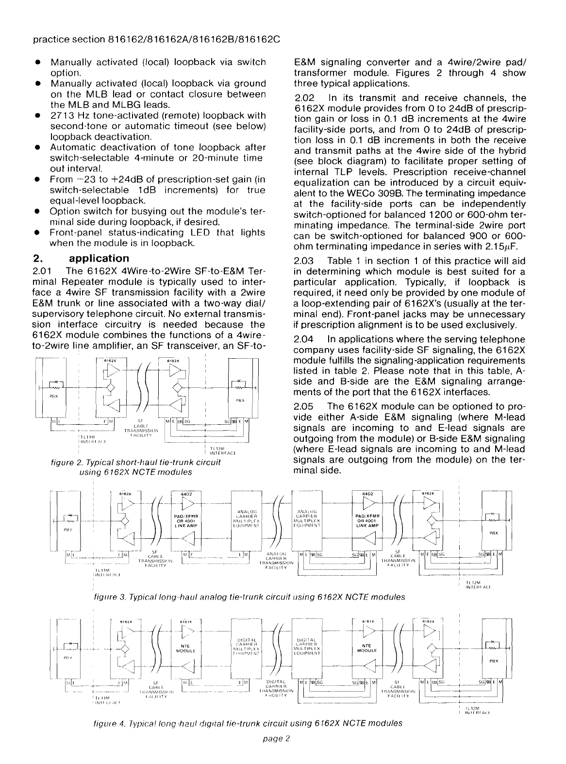
figure 2. Typical
short-haul
tie-trunk
circuit
using
6162X
NCTE
modules
E&M signaling
converter
and
a
4wire/2wire
pad/
transformer
module. Figures 2
through
4
show
three
typical applications.
2.02 In its
transmit
and
receive channels, the
6162X
module
provides from 0
to
24dB
of
prescrip-
tion
gain
or
loss in
0.1
dB
increments
at
the
4wire
facility-side ports,
and
from 0
to
24dB
of
prescrip-
tion
loss in
0.1
dB
increments
in both
the
receive
and
transmit
paths
at
the
4wire
side
of
the hybrid
(see
block
diagram) to
facilitate
proper
setting
of
internal TLP levels. Prescription receive-channel
equalization
can be
introduced
by
a
circuit
equiv-
alent
to
the WECo 309B. The terminating impedance
at
the
facility-side ports can
be
independently
switch-optioned
for
balanced
1200
or
600-ohm
ter-
minating impedance. The terminal-side 2wire port
can be
switch-optioned
for
balanced
900
or
600-
ohm
terminating
impedance
in
series
with
2.15flF.
2.03 Table 1in
section
1
of
this
practice
will aid
in
determining
which
module
is
best
suited
for
a
particular
application. Typically, if
loopback
is
required, it
need
only be provided by
one
module
of
a
loop-extending
pair
of
6162X's
(usually
at
the
ter-
minal end). Front-panel
jacks
may
be
unnecessary
if
prescription
alignment
is
to
be used exclusively.
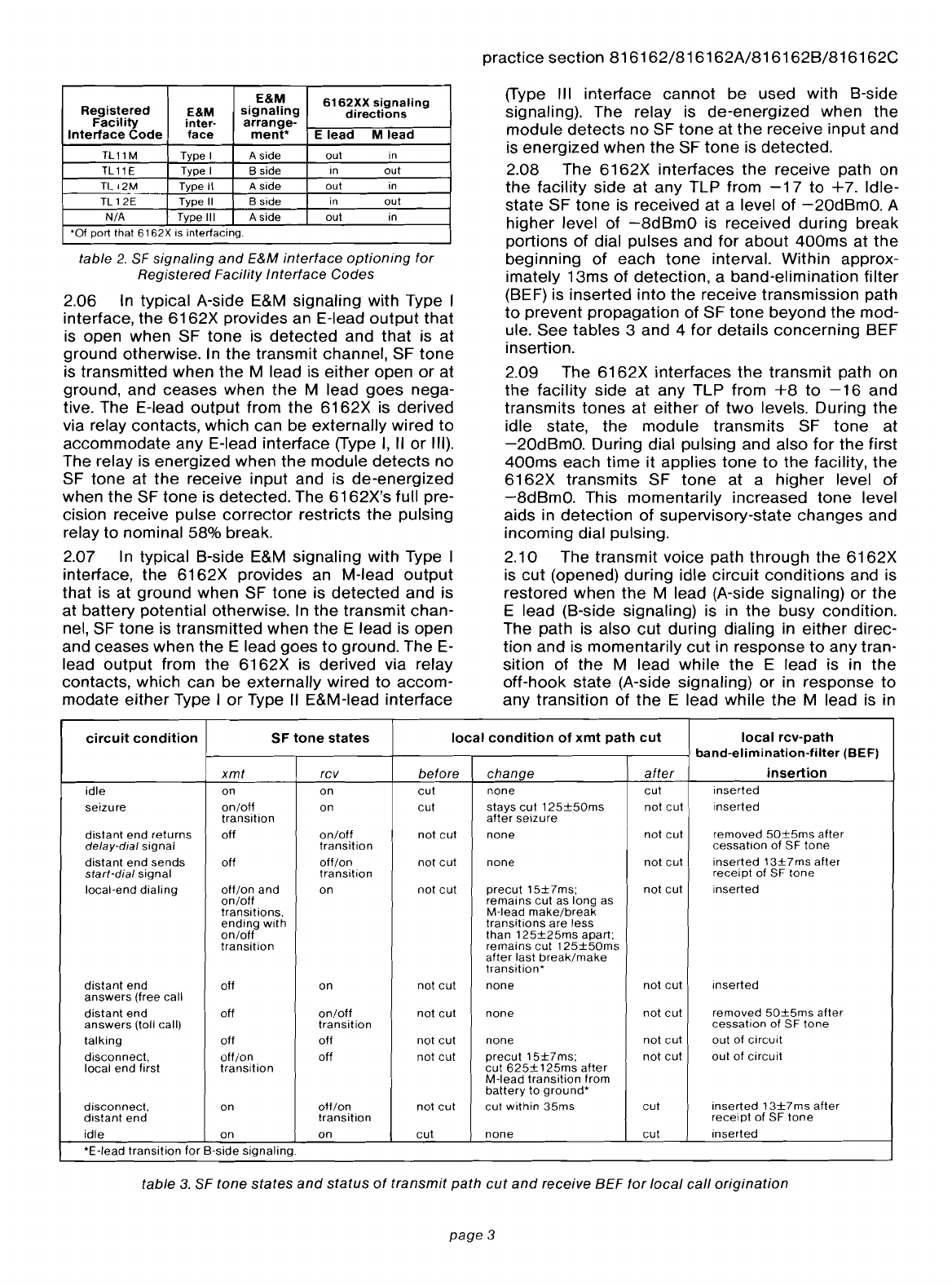
2.04 In
applications
where
the
serving
telephone
company
uses
facility-side SF signaling,
the
6162X
module fulfills
the
signaling-application requirements
listed in
table
2.
Please
note
that in
this
table, A-
side and B-side
are
the
E&M signaling arrange-
ments
of
the
port
that
the
6162X
interfaces.
2.05 The
6162X
module
can be
optioned
to
pro-
vide
either
A-side E&M signaling (where M-Iead
signals are
incoming
to
and E-Iead signals are
outgoing
from
the
module)
or
B-side E&M signaling
(where E-Iead signals are
incoming
to
and M-Iead
signals
are
outgoing
from
the
module) on the ter-
minal side.
figure
3.
Typicallong-/Jaul
analog
tie-trunk
circuit
using
6162X NCTE
modules
figUle
4.
Typical
long
-haul
dIg/tal
tie-trunk
circuit
using
6162X
NCTE
modules
page
2
E&M
6162XX
signaling
Registered
E&M
signaling
directions
Facility
inter-
arrange-
Interface
Code
face
ment*
Elead
M
lead
TL11
MType I
Aside
out
in
TLllE
Type IBside
in
Qut
TL
12M
Type
II
Aside
out
in
TL
12E Type
II
Bside
in
out
N/A Type
III
Aside
Qut
in
*Of port that 6162X is interfacing.
table
2.
SF
signaling
and
E&M
interface
optioning
for
Registered
Facility
Interface
Codes
2.06 In typical A-side E&M signaling with Type I
interface,
the
6162X
provides an E-Iead
output
that
is open
when
SF
tone
is
detected
and
that
is
at
ground
otherwise. In
the
transmit channel, SF
tone
is
transmitted
when
the
Mlead is
either
open
or
at
ground, and ceases when
the
Mlead
goes
nega-
tive. The E-Iead
output
from
the
6162X
is derived
via relay contacts, which can be
externally
wired
to
accommodate
any E-Iead
interface
(Type
I,
II
or
III).
The relay is energized
when
the
module
detects
no
SF
tone
at
the
receive
input
and is
de-energized
when
the
SF
tone
is
detected.
The
6162X's
full pre-
cision receive pulse
corrector
restricts
the
pulsing
relay
to
nominal 58% break.
2.07 In typical B-side E&M signaling
with
Type I
interface,
the
6162X
provides an M-Iead
output
that
is at
ground
when
SF
tone
is
detected
and is
at
battery
potential otherwise. In
the
transmit
chan-
nel, SF
tone
is
transmitted
when
the
Elead is open
and ceases
when
the
Elead
goes
to
ground. The E-
lead
output
from
the
6162X
is derived via relay
contacts, which can
be
externally
wired
to
accom-
modate
either
Type I
or
Type
II
E&M-Iead
interface
practice
section
816162/816162A/816162B/816162C
(Type III
interlace
cannot
be
used with B-side
signaling). The relay is
de-energized
when
the
module
detects
no
SF
tone
at
the
receive
input
and
is
energized
when
the
SF
tone
is
detected.
2.08 The
6162X
interfaces
the
receive path on
the
facility
side
at
any
TLP from
-17
to
+7.
Idle-
state
SF
tone
is received
at
alevel
of
-20dBmO.
A
higher
level of
-8dBmO
is received
during
break
portions
of
dial pulses and for
about
400ms
at
the
beginning
of
each
tone
interval.
Within
approx-
imately
13ms
of
detection,
a
band-elimination
filter
(BEF) is
inserted
into
the
receive transmission path
to
prevent
propagation
of SF
tone
beyond
the
mod-
ule. See
tables
3and 4
for
details
concerning
BEF
insertion.
2.09 The
6162X
interfaces
the
transmit
path on
the
facility side
at
any TLP from
+8
to
-16
and
transmits
tones
at
either
of
two
levels. During
the
idle state,
the
module
transmits
SF
tone
at
-20dBmO.
During dial pulsing and also
for
the
first
400ms
each
time
it
applies
tone
to
the
facility,
the
6162X
transmits
SF
tone
at a
higher
level of
-8dBmO.
This
momentarily
increased
tone
level
aids in
detection
of
supervisory-state
changes
and
incoming
dial pulsing.
2.10 The
transmit
voice path
through
the
6162X
is
cut
(opened)
during
idle
circuit
conditions
and is
restored
when
the
Mlead (A-side signaling)
or
the
Elead (B-side signaling) is in
the
busy
condition.
The path is also
cut
during dialing in
either
direc-
tion
and is
momentarily
cut
in
response
to
any tran-
sition of
the
Mlead
while
the
Elead is in
the
off-hook
state
(A-side signaling)
or
in
response
to
any
transition
of
the
Elead
while
the
Mlead is in
circuit
condition
SF
tone
states
local
condition
of
xmt
path
cut
local
rev-path
band-elimination-filter
(BEF)
xmt
rcv before change
after
insertion
idle
on
on
cut
none
cut
inserted
seizure
on/off
on
cut
stays
cut
125±50ms
not
cut
inserted
transition
after
seizure
distant
end
returns
off
on/off
not
cut
none
not
cut
removed
50±5ms
after
delay-dial
signal
transition
cessation
of
SF
tone
distant
end
sends
off
off/on
not
cut
none
not
cut
inserted
13±7ms
after
start-dial
signal
transition
receipt
of
SF
tone
local-end
dialing
off/on
and
on
not
cut
precut
15±7ms;
not
cut
inserted
on/off
remains
cut
as
long
as
transitions,
M-Iead
make/break
ending
with
transitions
are
less
on/off
than
125±25ms
apart;
transition
remains
cut
125±50ms
after
last
break/make
transition*
distant
end
off
on not
cut
none
not
cut
inserted
answers
(free call
distant
end
off
on/off
not
cut
none
not
cut
removed
50±5ms
after
answers
(toll call)
transition
cessation
of
SF
tone
talking
off off
not
cut
none
not
cut
out
of
circuit
disconnect,
off/on
off
not
cut
precut
15±7ms;
not
cut
out
of
circuit
local
end
first
transition
cut
625±125ms
after
M-Iead
transition
from
battery
to
ground*
disconnect,
on
off/on
not
cut
cut
within
35ms
cut
inserted
13±7ms
after
distant
end
transition
receipt
of
SF
tone
idle
on on
cut
none
cut
inserted
*E-Iead
transition
for
B-side
signaling.
table
3. SF
tone
states
and
status
of
transmit
path
cut
and
receive
BEF
for
local
call
origination
page
3

practice
section
816162/816162A/816162B/816162C
circuit
condition
SF
tone
states
local
condition
of
xmt
path
cut
local
rev-path
band-elimination-filter
(BEF)
xmt
rev before change
after
insertion
idle
on
on
cut
none
cut
inserted
seizure,
distant
end
on
on/off
cut
remains
cut
625±
not
cut
removed
50±5ms
after
transition
125ms
after
cessation
cessation
of
SF
tone
of
SF
tone
distant
end
returns
on/off
off
not
cut
cut
1
25±50ms
after
not
cut
out
of
circuit
delay-dial
signal
transition
M-Iead
transition
from
ground
to
battery*
local
end
returns
off/on
off
not
cut
precut
15±7ms;
re-
not
cut
out
of
circuit
start-dial
signal
transition
mains
cut
625±125ms
after
M-Iead
transition
from
battery
to
ground*
distant
end
on
off/on
and
not
cut cut
within
7ms
of
not
cut
inserted
13±7ms
after
1ransmits
on/off
tran-
receipt
of
first
tone
receipt
of
first
tone
pulse;
dial
pulses
sitions,
ending
pulse;
remains
cut
as
remains
in
circuit
until
50±
with
on/off
long
as
incoming
break/
5ms
after
last
incoming
on/
transition
make
transitions
are off
transition
or
225±50ms,
less
than
625±125ms
whichever
is
longer
after
last
incoming
on/
off
transition
local-end
on
off
not
cut
none
not
cut
out
of
circuit
answers
(free call)
local
end
on/off
off
not
cut
cut
125±50ms
after
not
cut
out
of
circuit
answers
(toll call)
transition
M-Iead
transition
from
ground
to
battery*
talking
off off
not
cut
none
not
cut
out
of
circuit
disconnect,
off
off/on
not
cut
none
not
cut
inserted
13±7ms
after
distant
end
I
transition
receipt
of
SF
tone
disconnect,
off/on
on
not
cut
I
precut
15±7ms;
then
cut
inserted
local
end
transition
continuously
cut
idle
on
on
cut
none
cut
inserted
*E-Iead
transition
for
B-side
signaling.
table
4.
SF
tone
states
and
status
of
transmit
path
cut
and
receive
BEF
for
distant-location
call
origination
E
X
PBX
TRUNK
CIRCUIT
the
off-hook
state
(B-side signaling). These
path
cuts
prevent
transmission
of
noise, transients,
speech,
and
other
interfering
signals
during
critical
signaling
intervals.
2.11
Figures
5
through
9
show
the
various
E&M
signaling
interfaces
listed
in
table
2.
Either
Type
I,
II,
or
III E&M
signaling
interface
can
be
selected
via
switch. Type Iis
often
used
with
electromechanical
switching
systems,
while
Types
II
and
III are
often
used
in
electronic
switching
environments.
figure
5.
Type I
E&M
interface
(TL
11
M); A
side
I
c:
23
1>--<
~~~
E1
'E
~
----;7
-48V
EI
19 I
SG
>---<
<SG
l
I=
./
0
1,1
-48V~
1>---<
::=JB
M
M.LEAD
21
1
~DETECTOR
~
1>-<
M
- 1
________
~6~X.J
figure
6.
Type
1/
E&M
interface
(TL 12M); A
side
page
4
, 1
E
23",
1>---< L..--J
HEAD
L..:".
~
ex
;;[>-<1::"
Imi'"'1
/
u,
_,
MLEAD
~I
I
n
DETECTORI
M
/'
>-<
IM
- I M
o1I 1
-48V",=<---tr.:::;; 5B>
1>-----<
1
5B
6162X
I 1
PBX
TRUNK
CIRCUIT
__________
. L _
figure
7.
Type
1/1
E&M
interface;
A
side
-"----
I 1
L.-
I
E·LEAO
~"-
1>---<
1
./
-48v~1
I""C
E
_~48V
: :
I 1
21
I I
c-M'LEAD
MI>----<I<MI
DETECT~
=I I -
________
~6~x_1
L~X~R_'=_N~C~C_'=_I~
_
figure
8.
Type I
E&M
interface
(TL
11
E);
B
side
II
L..
I
E·LEAD
l-...E
....
:
>-<
I
::=J
-
48V
"'l
DETECTOR
I
E"7
1:E E
r-_-..:
1
..:...
9:;;. I>----<1
.J: 5G I5G
=1I
:./
Q
--...
c:
B
1>-<1~-48V
M
21
1 I
~'LEAD
M1
>-----<
1
<M
OETECTOR
1 -
6162X
I I PBX
TRUNK
CiRCUIT
-
___________
L _
figure
9.
Type /I
E&M
interface
(TL 12E); B
side

2.12 The
6162X
module
uses relay
contacts
to
derive E-Iead and M-Iead signaling. This facilitates
interfacing
with
nonstandard E-Iead and M-Iead
voltage levels and polarities.
When
these
modules
are used
with
Type
II
E&M interface, terminal-side
equipment
can use
any
convenient
voltage
or
polarity.
2.13 Generally, if
loopback
is
to
be used,
the
terminal-end
module
will be
the
one
requiring loop-
back
capabilities (6162A
or
6162C). Equal-level
loopback
is made possible via
the
loopback
level
switches,
which
provide from
-23
to
+24dB
of
gain
in
1
dB
increments. The
loopback
circuitry
also pro-
vides signaling
loopback
functions
for
remote
test-
ing
of
the
SF and E&M signaling circuitry.
Some
examples of signaling
loopback
use
are
as follows:
A.
After loopback is initiated,
2600Hz
tone
is
transmitted toward the terminal end at
-10dBmO
and again at
-20dBmO.
In both cases,
the
receive channel should
echo
back
an SF
tone
at
-20dBmO
after an initial
400ms
tone
burst at
an
augmented level of
-8dBmO.
B.
Pulsed SF
tone
is transmitted
toward
the
ter-
minal end. The receive
channel
should
echo
back
pulsed SF
tone
at anominal 58% break.
2.14 Several modes of
loopback
initiation and
removal are available; all are
selected
via
option
switches. These
modes
are
described
in
section
3
of this practice.
3.
installation
inspection
3.01 The
6162X
4Wire-to-2Wire SF-to-E&M Ter-
minal
Repeater
module
should be visually inspec-
ted upon arrival
to
find any
damage
incurred
during
shipment. If
damage
is noted, aclaim
should
immediately be filed with
the
carrier. If stored,
the
module
should
be visually
inspected
again
prior
to
installation.
mounting
3.02 The
6162X
mounts
in
one
position
of
a
Tellabs Type
10
Mounting
Shelf, in
one
position
of
a
Tellabs
262U
Universal
Network
Terminating Sys-
tem Assembly,
or
in
one
position
of
aTellabs
260A
Signaling and Terminating System Assembly, all
of
which are available in
configurations
for
relay-rack
and apparatus-case installation. The
module
plugs
physically and
electrically
into
a56-pin
connector
at
the
rear of its
shelf
or
assembly position.
3.03 In applications
where
a
6162X
module
is
to
be installed
in
a
262U
Assembly, no additional con-
nections
need be made. This is
because
all
of
the
assembly's internal
connections
are factory-
prewired and because external
wiring
is simplified
through
the
use of female
25-pair
connector-ended
cables arranged in
accordance
with
Universal Ser-
vice
Order
Code (USOC) RJ2HX. If
the
customer's
terminal
equipment
is cabled in
accordance
with
USOC RJ2HX,
direct
connection
between
the
262U
Assembly and
the
customer's
equipment
is
possible. If not,
cross-connections
between
the
practice
section
816162/816162A/816162B/816162C
assembly
and
the
local
terminal
equipment
must
be made
at
an
intermediate
connectorized
terminal
block
or
by means of an
optional
adapter
cable
available as alist
number
for
the
262U
Assembly.
installer
connections
3.04
When
a
6162X
module
is
to
be installed in a
conventional
Type 10 Shelf,
external
connections
to
the
module
must
be made.
Before
making any
connections
to
the
mounting
shelf
or
assembly,
make sure
that
power
is
off
and
modules
are
removed.
Modules
should
be
put
into
place
only
after
they
are
properly
optioned
and
after
wiring is
completed.
3.05 Table 5lists external
connections
to
the
6162X
module. All
connections
to
non-prewired
mountings
are made via
wire-wrapping
to
the
56-
pin
connector
at
the
rear
of
the
module's
shelf
or
assembly
position. Pin
numbers
are
found
on
the
body
of
the
connector.
connect:
to
pin:
4WIRE RCV TIP , 7
4WIRE RCV RING
13
4WIRE XMTTiP
41
4WIRE XMT RING
47
4WIRE RCV SX .......
..
...........
..
................
..
9
4WIRE XMT SX
43
2WIRE TIP (terminal side)
55
2WIRE RING (terminal side)
49
EXTERNAL PBN 5
and
15
Alead
51
Blead 3
Elead
23
Mlead
21
SB lead 1
SGlead
19
MLB
(manual loopback) 18
MLBG
(manualloopback
ground)
37
-BAIT
(-43
to
-52Vdc
filtered input)
35
GND (ground) 17
table
5.
External
connections
to
6162X
option
selection
3.06 A
number
of
option
switches
must
be set
before
the
6162X
can
be
placed
into
service.
These
switches
and
their
functions
are
described
in paragraphs 3.07
through
3.12. The
locations
of
the
switches
on
the
module's
printed
circuit
board
are
shown
in
figure
10. Table 6
summarizes
all
switch
options
and provides a
convenient
checklist
for
optioning
the
module.
impedance
matching
3.07 Two-position
slide
switches
S1
and
S2 on
the
main board
select
balanced
terminating
im-
pedance
of
either
600
ohms
or
1200
ohms
for
each
of
the
module's
facility-side ports as follows:
switch
port
81
receive
input
(facility
side)
S2
transmit
output
(facility
side)
Option
the
facility-side ports (rev in and
xmt
out) for
1200
ohms when interfacing loaded
cable
or
for
600
ohms when interfacing nonloaded cable or
carrier.
page
5
practice
section
816162/816162A/816162B/816162C
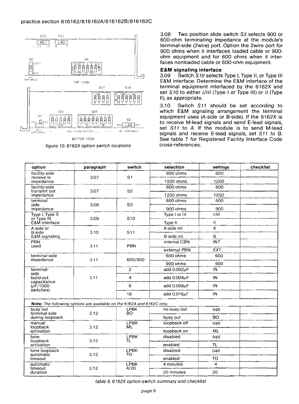
3.08
Two position slide switch S3 selects
900
or
600-ohm
terminating
impedance
at
the
module's
terminal-side (2wire) port.
Option
the
2wire port
for
900
ohms
when
it interfaces loaded
cable
or
900-
ohm
equipment
and
for
600
ohms
when it inter-
faces
nonloaded
cable
or
600-ohm
equipment.
E&M signaling
interface
3.09
Switch
SlO
selects
Type
I,
Type II,
or
Type III
E&M interface.
Determine
the
E&M interface of
the
terminal
equipment
interfaced by
the
6162X
and
set
S10
to
either
1/1/1
(Type I
or
Type III)
or
/I
(Type
II),
as appropriate.
3.1
0
Switch
S
11
shou
Id
be
set
according
to
which E&M signaling
arrangement
the
terminal
equipment
uses (A-side
or
B-side). If
the
6162X
is
to
receive M-Iead signals and
send
E-Iead signals,
set S
11
to
A.
If
the
module
is
to
send
M-Iead
signals and receive E-Iead signals,
set
S11
to
B.
See
table
7
for
Registered Facility Interface Code
cross-references.
-__
/
2W
I
MPEDANcr
517
516
522
54
~~~~~~B~
53
,
HT-_./
'------BW-
./
9001
c:.:::.IS:J
Ibu('
TOP
VIEW
BOTTOM
VIEW
511
521
figure
10.
6162X
option
switch
locations
52
~l?Vl
~6()O
510
option
paragraph
switch
selection
settings
checklist
facility-side
600
ohms
600
receive
in 3.07 51
impedance
1200
ohms
1200
facility-side
600
ohms
600
transmit
out
3.07
S2
impedance
1200
ohms
1200
terminal
600
ohms
600
side
3.08
53
impedance
900
ohms
900
Type
I,
Type
II
Type I
or
III
1/111
or
Type III
3.09
510
E&M
interface
Type
II II
A-side
or
A-side int. A
B-side
3.10
511
E&M
signaling
B-side int. B
PBN
internal
CBN
INT
used
3.11
PBN
external
PBN EXT
terminal-side
600
ohms
600
impedance
3.11
600/900
900
ohms
900
terminal-
2
add
0.002,uF IN
side
build-out
3.11
4
add
0.004,uF IN
capacitance
(,uF/1
000
8
add
0.008,uF IN
switches)
16
add
0.016,uF IN
Note:
The
following
options
are
available
on
the
6162A
and
6162C
only.
busy
out
LPBK
no
busy
out
(up)
terminal
side
3.12
BO
during
loop
back
busy
out
80
manual
LPBK
loopback
off
(up)
loopback
3.12
ML
activation
loopback
on
ML
tone
I
LPBK
disabled
(up)
loopback
3.12
TL
activation
enabled
TL
tone
loop
back
LPBK
disabled
(up)
automatic
3.12 TO
timeout
enabled
TO
automatic
LPBK
4
minutes
4
timeout
3.12
4/20
duration
20
minutes
20
table
6.
6162X
option-switch
summary
and
checklist
page
6
practice
section
816162/816162A/816162B/816162G
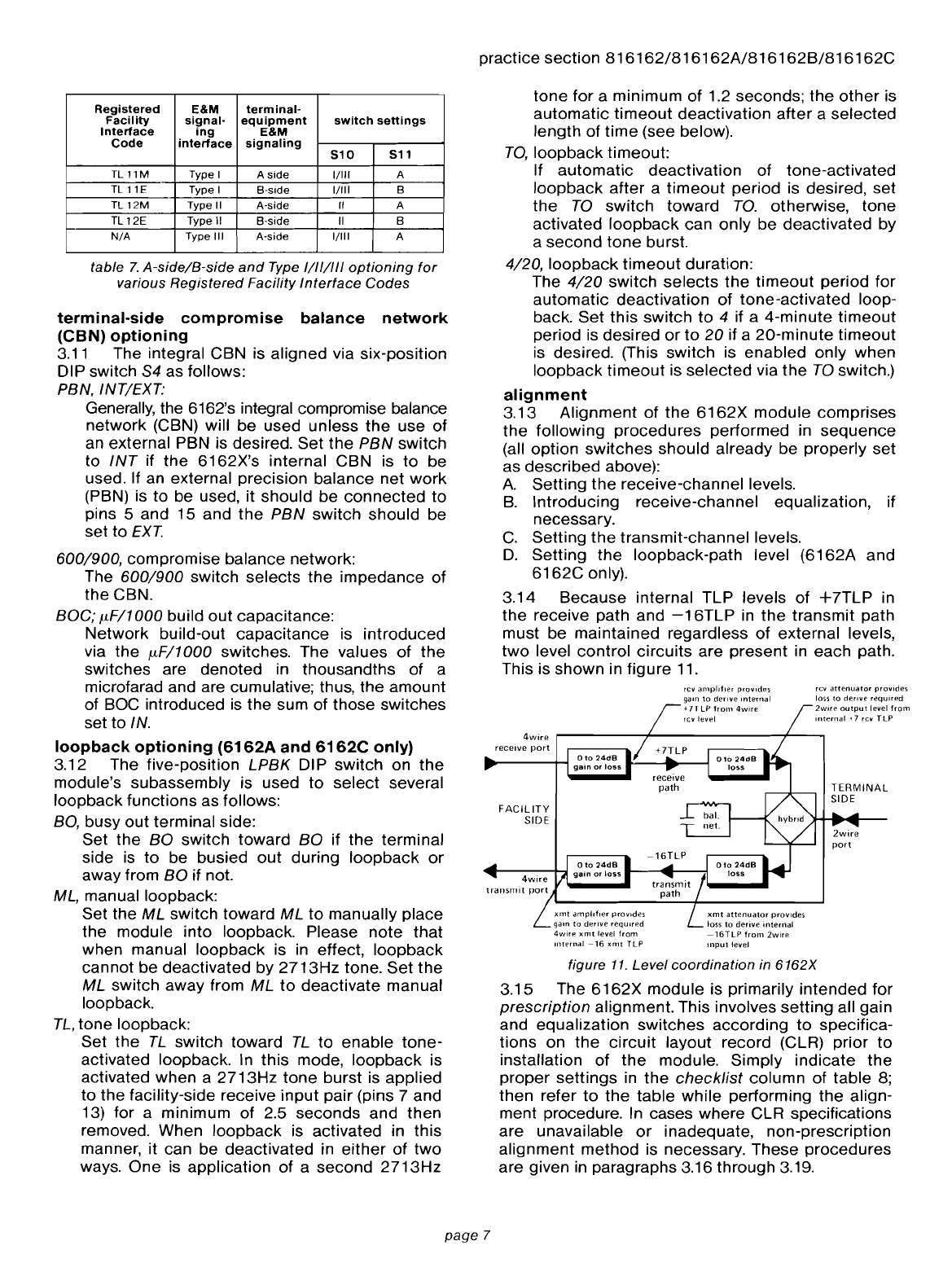
figure 11. Level
coordination
in
6162X
3.15 The
6162X
module
is primarily
intended
for
prescription
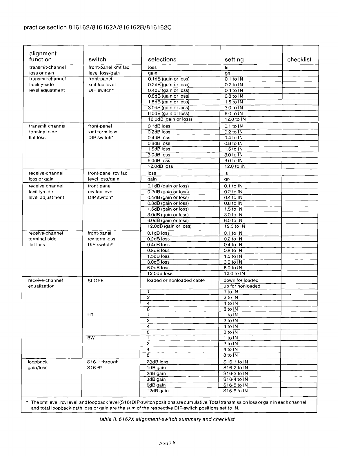
alignment. This involves
setting
all gain
and equalization
switches
according
to
specifica-
tions
on
the
circuit
layout record (CLR)
prior
to
installation of
the
module. Simply
indicate
the
proper
settings
in
the
checklist
column
of table 8;
then
refer
to
the
table
while
performing
the
align-
ment procedure. In cases where CLR specifications
are unavailable
or
inadequate, non-prescription
alignment method
is necessary. These
procedures
are given
in
paragraphs 3.16 through 3.19.
tone
for
aminimum
of
1.2 seconds;
the
other
is
automatic
timeout
deactivation
after
a
selected
length
of
time
(see below).
TO,
loopback
timeout:
If
automatic
deactivation
of
tone-activated
loopback
after
a
timeout
period
is desired, set
the
TO
switch
toward
TO.
otherwise,
tone
activated
loopback
can
only
be
deactivated
by
a
second
tone
burst.
4/20,
loopback
timeout
duration:
The
4/20
switch
selects
the
timeout
period
for
automatic
deactivation
of
tone-activated
loop-
back.
Set
this
switch
to
4if a
4-minute
timeout
period is
desired
or
to
20
if a
20-minute
timeout
is desired. (This
switch
is
enabled
only
when
loopback
timeout
is
selected
via
the
TO
switch.)
alignment
3.13
Alignment
of
the
6162X
module
comprises
the
following
procedures
performed
in
sequence
(all
option
switches
should
already
be
properly
set
as
described
above):
A.
Setting
the
receive-channel levels.
B.
Introducing
receive-channel equalization, if
necessary.
C.
Setting
the
transmit-channel
levels.
D.
Setting
the
loopback-path
level
(6162A
and
6162C
only).
3.14
Because
internal
TLP
levels
of
+7TLP in
the
receive path and
-16TLP
in
the
transmit
path
must be
maintained
regardless
of
external levels,
two
level
control
circuits
are
present
in
each path.
This is
shown
in
figure
11.
2wire
port
TERMINAL
SIDE
fell
attenuatar
provides
loss
to
derive
required
2wire
output
level
from
internal
i7
rell
TLP
xmt
attenuatar
provides
loss
to
derive
internal
-16TLP
from
2wire
mput
level
rev
amplifier
provides
gam
to
derive
internal
+7TLP
from
4wire
rev level
xmt
<Impllfier
provides
gam
to
derive
requHp.d
4witf!
xmt
level
from
lI1ternal
-16
xmt
TLP
FACILITY
SIDE
4wire
//I
receive
port
4wire
transmit
port
Registered
E&M
terminal-
Facility
signal-
equipment
switch
settings
Interface
ing
E&M
Code
interface
signaling
S10
S11
TL
11M
Type I A
side
1/111
A
TL
11E
Type I
B-side
1/'" B
TL
12M
Type
II
A-side
II
A
TL12E
Type
II
B-side
II
B
N/A
Type III A-side
1/111
A
table
7.
A-side/B-side
and
Type
1/11/111
optioning
for
various
Registered
Facility
Interface
Codes
terminal-side
compromise
balance
network
(CBN)
optioning
3.11 The integral CBN is
aligned
via six-position
DIP switch
84
as follows:
P8N,INT/EXT:
Generally, the 6162's integral compromise balance
network
(CBN) will be used
unless
the
use
of
an external PBN is desired.
Set
the
P8N
switch
to
INT
if
the
6162X's
internal CBN is
to
be
used. If an external precision balance
net
work
(PBN) is
to
be used, it
should
be
connected
to
pins 5and 15 and
the
P8N
switch
should
be
set
to
EXT
600/900,
compromise balance
network:
The
600/900
switch
selects
the
impedance
of
the
CBN.
80G;
jLF/1
000
build
out
capacitance:
Network
build-out
capacitance
is
introduced
via the jLF/1000 switches. The values
of
the
switches
are denoted in thousandths
of
a
microfarad and are cumulative; thus, the
amount
of BOC introduced is the sum of those switches
set
to
IN.
loopback
optioning
(6162A
and
6162C
only)
3.12 The five-position
LP8K
DIP
switch
on
the
module's
subassembly
is used
to
select
several
loopback
functions
as follows:
80,
busy
out
terminal side:
Set
the
80
switch
toward
80
if
the
terminal
side is
to
be busied
out
during
loopback
or
away from
80
if not.
ML,
manualloopback:
Set the
ML
switch toward
ML
to
manually
place
the module
into
loopback. Please
note
that
when manual
loopback
is
in
effect,
loopback
cannot
be deactivated
by
2713Hz
tone.
Set
the
ML switch away from
ML
to
deactivate
manual
loopback.
TL,
tone
loopback:
Set
the
TL
switch toward
TL
to
enable
tone-
activated loopback. In
this
mode,
loopback
is
activated
when
a
2713Hz
tone
burst is
applied
to
the
facility-side receive
input
pair (pins 7and
13) for aminimum of 2.5
seconds
and
then
removed. When
loopback
is activated in
this
manner, it can be deactivated in
either
of
two
ways.
One
is application of a
second
2713Hz
page
7
practice
section
816162/816162A/8161628/816162C
alignment
function
switch
selections
setting
checklist
transmit-channel
front-panel
xmt
fac
loss
Is
loss
orgain
level
loss/gain
gain
gn
transmit-channel
front-panel
0.1
dB
(gain
or
loss)
0.1
to
IN
facility-side
xmt
fac
level
0.2dB
(gain
or
loss) 0.2
to
IN
level
adjustment
DIP
switch*
OAdB
(gain
or
loss)
004
to
IN
0.8dB
(gain
or
loss) 0.8
to
IN
1.5dB
(gain
or
loss) 1.5
to
IN
3.0dB (gain
or
loss) 3.0
to
IN
6.0dB (gain
or
loss) 6.0
to
IN
12.0dB
(gain
or
loss) 12.0
to
IN
transmit-channel
front-panel
0.1dB
loss
0.1
to
IN
terminal-side
xmt
term
loss
0.2dB
loss 0.2
to
IN
flat loss DIP
switch*
OAdB
loss
004
to
IN
0.8dB
loss
0.8
to
IN
1.5dB
loss 1.5 to IN
3.0dB loss 3.0
to
IN
6.0dBloss
6.0
to
IN
12.0dB
loss
12.0to1N
receive-channel
front-panel
rcv
fac
loss
Is
loss
or
gain
level
loss/gain
gain
gn
receive-channel
front-panel
0.1
dB
(gain
or
loss)
0.1
to
IN
facility-side
rcv
fac
level
0.2dB
(gain
or
loss) 0.2
to
IN
level
adjustment
DIP
switch*
OAdB
(gain
or
loss)
OAtolN
0.8dB
(gain
or
loss) 0.8
to
IN
1.5dB
(gain
or
loss) 1.5 to IN
3.0dB
(gain
or
loss) 3.0
to
IN
6.0dB (gain
or
loss) 6.0
to
IN
12.0dB
(gain
or
loss) 12.0
to
IN
receive-channel
front-panel
0.1dB
loss
0.1
to
IN
terminal-side
rcv
term
loss
0.2dB
loss 0.2
to
IN
flat
loss
DIP
switch*
OAdB
loss
004
to
IN
0.8dB
loss 0.8
to
IN
1.5dB
loss 1.5
to
IN
3.0dB
loss
3.0
to
IN
6.0dB
loss
6.0
to
IN
12.0dB
loss
12.0to1N
receive-channel
8LOPE
loaded
or
non
loaded
cable
down
for
loaded
equalization
up
for
nonloaded
1 1
to
IN
2
2toiN
4 4 to IN
8
8toiN
HT 11
to
IN
2
2toiN
4
4toiN
8
8toiN
BW 11
to
IN
2
2toiN
4
4toiN
8
8toiN
loopback
816-1
through
23dB
loss
816-1
to
IN
gain/loss
816-6*
1dB
gain
816-2to1N
2dB
gain
816-3
to
IN
3dB
gain
816-4to
IN
6dB
gain
816-5to1N
12dB
gain
816-6
to
IN
..
Thexmt
level. rcv level,
and
loopback
level
(816)
DI P-switch
positions
are
cumulative.
Total
transmission
loss
orgain
in
each
channel
and
totalloopback-path
loss
or
gain
are
the
sum
of
the
respective
DIP-switch
positions
set
to
IN.
table 8.
6162X
alignment-switch
summary
and
checklist
page8

Note:
Because
the 6162B
and
6162C
do
not
have
test jacks,
non-prescription
alignment
of
these
modules is
not
recommended.
If,
however, non-
prescription
alignment
is necessary, the use
of
a
Tellabs 9801
or
9802
Card
Extender
or
an
external
jackfield
is
strongly
recommended
to
simplify
align-
ment. The
6162B/C
can also be
aligned
if
mea-
surements
are
made
at
the
numbered
pins
at
the
rear
of
the
module's
mounting
position
and
care is
taken to
avoid
double terminations. In
some
in-
stances,
it
may
be necessary to remove
some
wire-
wrapping
connections
at
the
module's
mounting-
shelf
connector
before
tone can be
applied
or
measured.
non-prescription
alignment
3.16
Initial
settings:
A.
Ensure that all
impedance
options
are
properly
set.
B.
Set ali positions
of
the
front-panel
xmt
fac level,
xmt
term loss, rcv fac level, and rcv term loss DIP
switches
to
the
out
position
for
no gain
or
loss.
DIP
switches
to
the
out
position
for
no
gain
or
loss.
C.
Set all receive
equalization
DIP
switches
(SLOPE,
HT,
and
BW)
to
the
out
position
for
no
equalization.
D.
Set all loopback-Ievel DIP
switches
to
the
up
position (6162A and
6162C
only)
for
no
loop-
back
path gain
or
loss.
3.17
Receive-channel
level
adjustment:
A.
Connect
the
receive portion (properly ter-
minated) of atransmission measuring
set
(TMS)
to
the
2W
in jack. Request
the
distant
location
to
send
1004Hz
at the level specified on the
CLR. Verify that tone is present and measure its
level.
B.
Determine
whether
the
measured level is
higher
or
lower
than
+7dBm.
1.
If the measured level is
lower
than
+7dBm,
set the front-panel rcv fac level
gn/ls
switch
to
gn. Then
set
to
IN
the
proper
combination
of front-panel rcv fac level
switches
that
equals
the
required gain.
2.
If
the
measured terminal-side level is
higher
than +7dBm,
set
the
front-panel rcv fac level
gn/ls
switch
to
Is.
Then
set
to
IN
the
proper
combination
of
front-panel rcv fac level
switches
that
equals
the
required
amount
of
loss.
C.
Refer
to
the
CLR
for
the specified receive out-
put level.
D.
Calculate
the
difference
between
this
specified
output
level and
the
internally derived
+7dBm
level.
E.
Set
to
in the
proper
combination
of
front-panel
rcv term loss DIP-switch
positions
that
adds
up
to
this
difference.
3.18
Transmit-channel
level
adjustment:
A.
Remove
the
transmit
speech
path
cut
by seiz-
ing the
circuit
from
the
terminal side.
B.
Connect
the transmit portion
of
the
TMS (prop-
erly terminated)
to
the
2W
in jack.
Send
1004Hz
from the terminal-side location at
O.OdBmO.
practice
section
816162/816162A/816162B/816162C
C.
Connect
the
receive
portion
of
the
TMS (prop-
erly terminated)
to
the
4W
xmt
out
jack.
D.
Set
to
IN
the
proper
combination
of
xmt
term
loss DIP-switch
positions
so
that
a
-16dBm
level is achieved.
E.
Refer
to
the
CLR
for
the
specified
level at
the
distant
end.
F.
Request
personnel
at
the
distant
end
to
measure and report
their
receive level.
G.
Calculate
the
difference
between
this
specified
level and
the
measured level.
H.
Determine
whether
the
specified
level is
higher
or
lower
than
the
measured level.
1.
If
the
specified
level is lower,
then
set
the
front-panel
xmt
fac level
gn/ls
switch
to
gn.
Then
set
to
IN
the
proper
combination
of
front-panel
xmt
fac level
switches
that
equals
the
calculated
difference.
2.
If
the
specified level is higher,
then
set
the
front-panel
xmt
fac level
gn/ls
switch
to
Is.
Then set
to
IN
the
proper
combination
of
front-panel
xmt
fac level
switches
that
equals
the
calculated
difference.
receive-channel
equalization
alignment
3.1
9The receive-channel equalizer on the 6162X
is
functionally
identical
to
the
Western Electric
309B
Prescription Equalizer. Prescription
settings
for
the
equalizer
can be
found
in BSP (Bell System
Practice)
section
332-912-232,
and manual align-
ment
procedures
for
the
equalizer
can be
found
in
BSP
section
332-912-234.
loopback
level
adjustment
3.20
To
adjust
the
6162X's loopback-Ievel-control
circuitry
to
provide equal-level loopback,
proceed
as follows:
A.
From
the
CLR,
determine
the
specified
transmit
input
and receive
output
levels.
B.
Subtract
the
receive
output
level from
the
transmit
input
level. The result is
the
amount
of
gain required in
the
loopback
path.
C.
On
the
6162X's
loopback
subassembly,
set
to
on
that
combination
of
LPBK
LVL DIP-switch
positions
which
most
closely
approximates
the
amount
of
gain
determined
in
step
B.
4.
circuit
description
4.01 This
circuit
description
is intended,
to
familiarize
you
with
the
operation
of
the
6162X
4Wire-to-2Wire
SF-to-E&M Terminal
Repeater
modules.
Attempts
to
troubleshoot
these
modules
internally are
not
recommended
and may void
your
warranty. Please
refer
to
the
6162X
block
diagram,
section
5of this practice, as an aid in
following
this
circuit
description.
receive
path
4.02 A
transformer
at
the
4wire
receive
input
port
interfaces
the
transmission facility and derives
tip, ring, and
simplex
leads. The transformer's
secondary
windings
are
coupled
to
aresistive
switch-selectable
600-
or
1200-ohm
impedance-
matching
network
and
to
abuffer.
page
9
practice
section
816162/816162A/816162B/816162C
4.03
Lightning
protection
is
provided
forthe
buffer
by
varistors. The
output
of
the
buffer
is
connected
to
prescription
rcv fac level
circuitry
for
level
coordina-
tion and
thence
to
a
series-connected
active pres-
cription
amplitude
equalizer
that
is
equivalent
to
the
Western
Electric
309B
Prescription
Equalizer. The
output
of
the
amplitude
equalizer
is
connected
to
a
BEF
band-elimination
filter
(BEF),which,
at
the
appro-
priate time,
filters
out
2600Hz
SF
tone. The rcv term
loss
attenuating
network
provides
the
proper
ter-
minal
equipment
levels
without
affecting
the
levels
of
the
signal
that
the
SF
detector
receives. The conver-
sion from
4wire
to
2wire
transmission
is
achieved
by
the
integral
magnetic
hybrid, which drives
the
2wire
port via
switch-selectable
600
or
1200-ohm
imped-
ance-matching circuitry.
transmit
path
4.04
Signals
from
the
2-coil
hybrid
drive
abuffer,
which, in turn,
feeds
the
prescription
xmt
term loss
circuitry
for
terminal-side
level
coordination,
after
which
SF
tones
from
the
2600Hz
oscillator
can be
inserted
via
the
SF tone
control
circuit. The
transmit
signal is
then
routed
through
the
xmt
fac level pre-
scription
level-control
circuitry
for
facility-side level
coordination
and
then
is
applied
to
adriver,
which
is
protected
from
lightning
by
varistors. The driver
drives
the
4wire
transmit
output
port
via
switch-
selectable
600
or
1200-ohm
impedance-matching
circuitry
and
via a
transformer
that
derives
tip, ring,
and
simplex
leads.
terminal-side
2wire
section
4.05 The
6167X
uses atoll-grade
magnetic
hybrid
for
4wire-to-2wire
conversion. An integral com-
promise balance
network
(CBN) is
connected
to
the
hybrid
to
maximize transhybrid loss by simulating
600
or
900
ohm terminal-side (2wire) terminating
impedance and providing prescription build-out
capacitance. If desired,
the
integral CBN can
be
switched
out
of
the
circuit and an external
PBI\J
can
be
connected
to
pins 5and 15.
SF
signaling
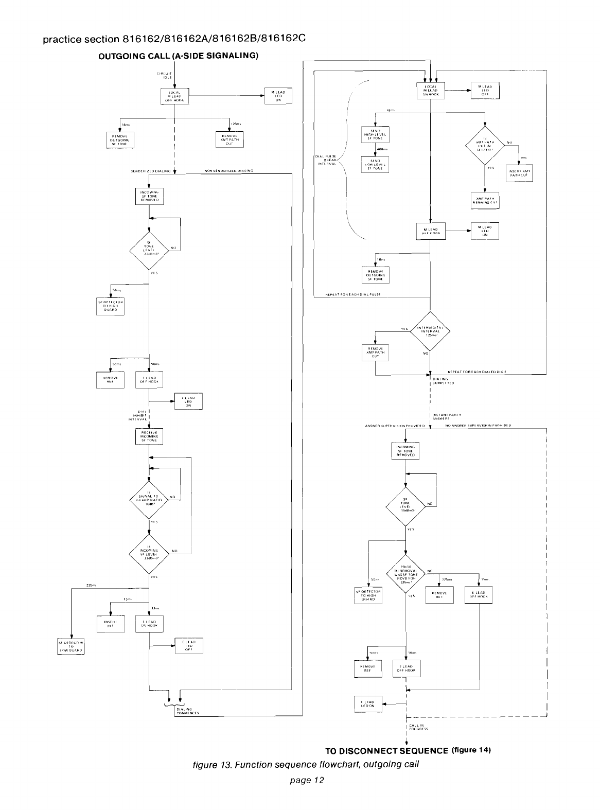
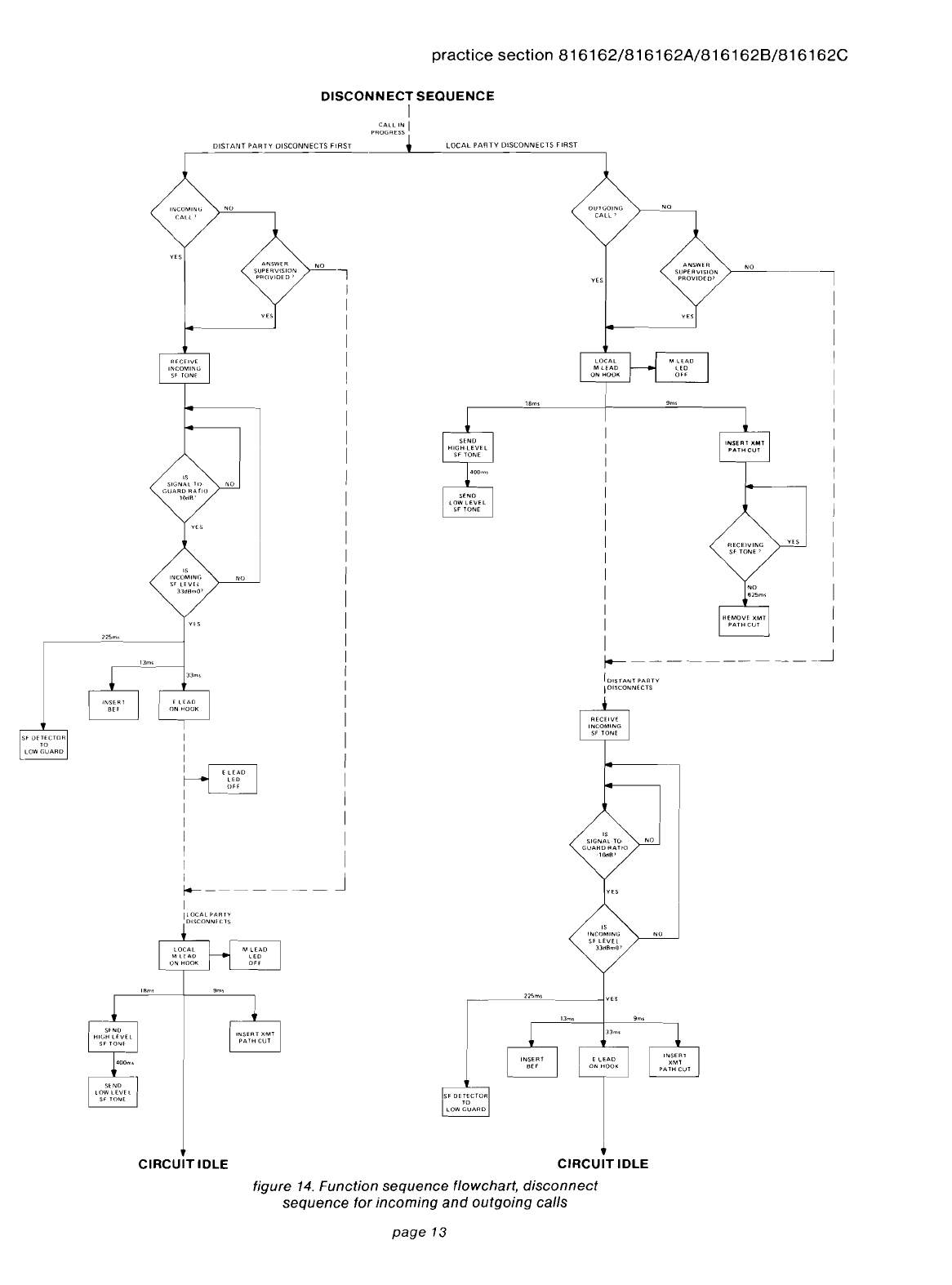
4.06 At
the
terminal
end
of
the
SF
signaling
path,
the
E&M
signaling
interface
circuit
determines
the
state
of
the
local Mlead (A-side signaling)
or
Elead
(B-side signaling)
and
communicates
with
the
con-
trollogic
to
initiate
proper
transmit
path
cut
and
SF
tone
transmission.
The
control
logic
circuit
also
receives an
indication
from
the
SF
detector
when
tone
is
received
and
causes
the
E&M
signaling
interface
to
output
the
proper
E-Iead
or
M-Iead
states.
Figures
11, 12,
and
13
are
function
sequence
flowcharts
that
illustrate
the
signaling
operation
of
the
6162X
with
A-side signaling.
Horizontal
paths
identify
events
occuring
simulta-
neously,
and
vertical
paths
denote
sequential
events.
Dotted
lines
indicate
elapsed
time.
loopback
(6162A
and
6162C
only)
4.07 Both
transmission
loopback
and
signaling
loopback
of
the
module
are
activated
when
the
LB
relay operates. This relay is
controlled
by
the
loop-
back
detector
and
control
circuit,
which
operates
the
relay
when
anyone
of
the
following
happens:
A. A
2713Hz
tone
of
correct
level and
duration
is
detected
in
the
receive path.
B.
The external loopback lead (pin 18) is grounded
or
connected
to
pin 37.
C.
The
ML
DIP
switch
is closed.
4.08 In case A(tone loopback), loopback can be
deactivated by either asecond
2713Hz
tone
or by
automatic
timeout
circuitry. In case
B,
if
the
external
loopback
lead is grounded, the
ground
must be
removed
to
deactivate loopback.
In
case
C,
if
the
ML
switch is closed, it must be opened again to deac-
tivate loopback.
4.09 When the
module
is
in
loopback, the LB relay
contacts disconnect
the
terminal-side port from the
6162X
circuitry and
connect
the
output
of
the
receive-path output driver to
the
input
of
the transmit-
path buffer. Signaling loopback is such that SF
signals received at
the
module are echoed back
onto
the facility.
power
supply
4.10
The
power
supply
in
the
6162X
module
is a
series-regulated
bipolar
supply
that
uses
a
zener
diode
to
derive
a
reference
source. A
diode
in
series
with
the
negative
input
lead
protects
against
reversed
voltage
connections.
6.
specifications
I
transmission
I
alignment
level ranges, facility-side
ports
4wire
rcv
port:
-17
to
+
7TLP
(interface
levels
above
+7TLP
not
recommended)
4wire
xmt
port:
-16
to
+8TLP
(interface
levels
below
-16TLP
not
recommended)
alignment
level ranges, 2wire
port
2wire-port
input:
+8
to
-16TLP
2wire-port
output:
+7
to
-17TLP
overload
points
4wire
rcv
port:
OdBmO
4wire
xmt
port:
+3dBmO
2wire-port
input:
+3dBmO
2wire-port
output:
OdBmO
facility-side gain
or
loss (xmt
and
rcv)
o
to
24dB
of
gain
or
0
to
24dB
of
loss
in
switch-
selectable
0.1dB
increments,
with
gain
or
loss
selected
via
switch
option
terminal-side loss
(xmt
and
rcv)
o
to
24dB
of
loss
in
switch-selectable
0.1
dB
increments
receive-channel
amplitude
equalization
slope-type
equalization
for
nonloaded
cable
or
bump-
type
equalization
for
loaded
cable
(functionally
equivalent
to
that
provided
by
WECo
309B
Prescrip-
tion
Equalizer)
total
harmonic
distortion
less
than
1%
at
overload
point
receive-in-to-2wire
frequency
response re 1004Hz
(BEF removed)
300
to
500Hz
+0.0,
-1.7dB
500
to
3400Hz
±
1.0dB
specifications
continued
on
page
15
page
10

practice section
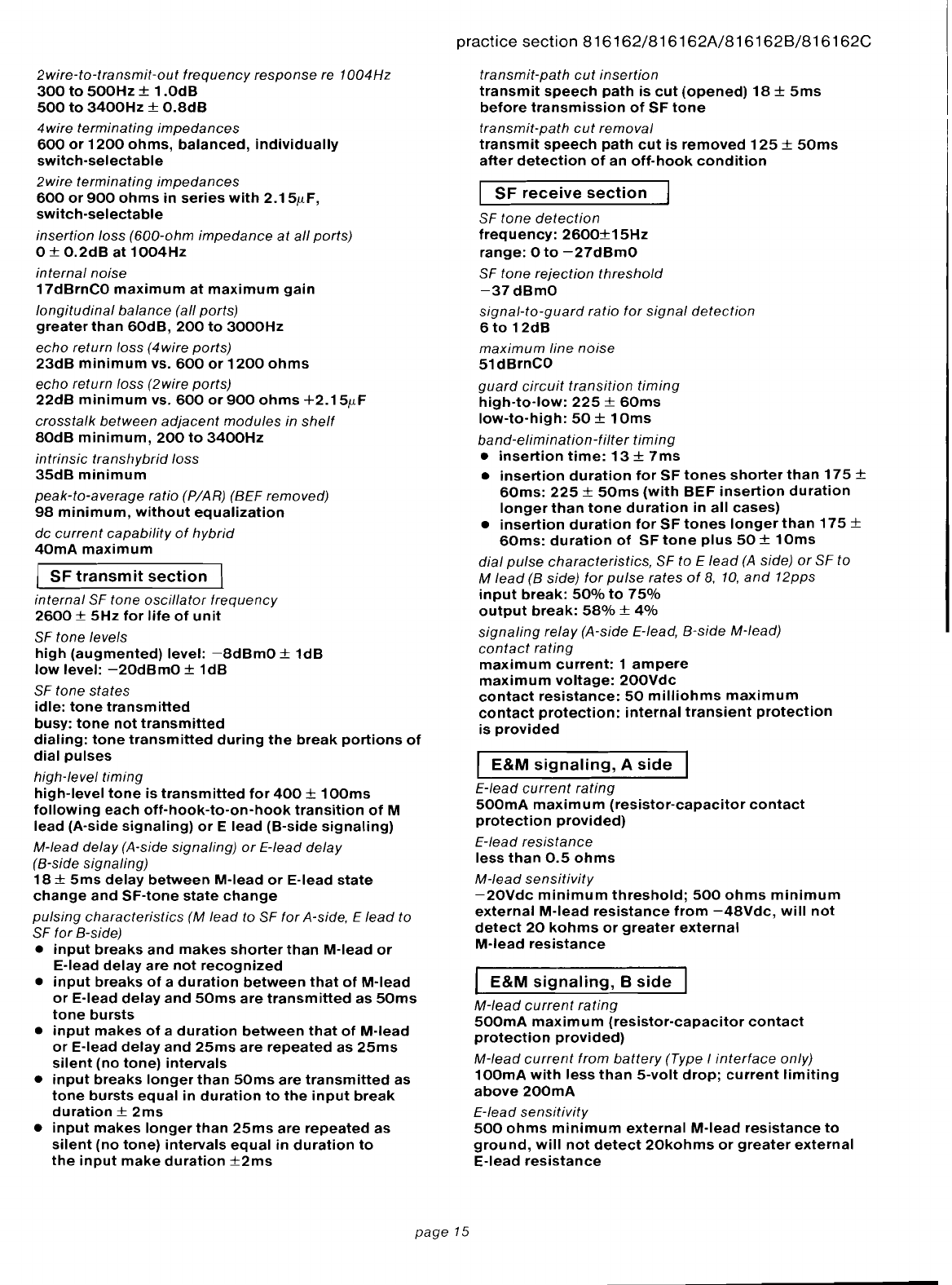
816162/816162A/816162B/816162C
INCOMING
CALL
(A-SIDE
SIGNALING)
RfMUVl
""
N,·'
~~
~
DIALING
I
COMPI
ETlL>
I
I~
~-~
'8m>
I ,
..
5('<'
"MT
I
PATH
el"
,
'~
I
)
12"m,
:
flEMOVF
XMT
I
PATHCUI
,
L------
r
--------------
~
[M()\n
"""
'"
'M;~;'"
,,,,
L-_--I.
J"""""
..
""'0,"""""."
I
"".,,,,,,,
'''"''''''',''
NONSfN[)fRIHLJ
DIALING
-----------!
~
oc
..
...
t[AIl
~
flN
HOOK
~
'"'"'----
~''"'-
----{]J"""
'CO
""
,lNO
ItU,ftllVfl
"
IllN!
I
IN~,HT
~MT
PATH
UiT
400m,
'''~\~':H
~
"
'''Nf
tll',m,
HFp~~~~~~'
~
~
'--1;;;;'"
"
~
'·~NlJ[
Hllf[)
(lIAIINt,
I
~:(~~~~SS
+
TO
DISCONNECT
SEQUENCE
(figure
14)
figure 12. Function sequence flowchart,
incoming
call
page
11
-m
''"''
Illl
OFF
I
",eo"
n,",,,
""",""
L----------{3U
practice section
816162/816162A/816162B/816162C
OUTGOING
CALL
(A-SIDE
SIGNALING)
I
I
I
I
I
I
I
I
I
I
I
1
I
I
I
I
I
I
I
I
I
______________
---J
I
DIS
TAN
I
PARTY
..
ANSWE:~
ANSWER
SUP,
flVISHJN
f'HOVIDI
[)
f
LEAD
OFF
HOOK
~~
~I
E I
fAD
l''''
HO<)~
I
I
t
TO
DISCONNECT
SEQUENCE
(figure
14)
figure
13.
Function
sequence
flowchart,
outgoing
call
page
12
practice
section
816162/816162A/816162B/816162C
DISCONNECT
SEQUENCE
I
PR~~~LE~~
I
DISTANT
PARTY
DISCONNECTS
F!RST
LOCAL
PARTY
DISCONNECTS
FIRST
INCOMING
C.ALL'
OUTGOING
CALL'
RECEIVING
Sf-
TONE'
ANSWER
SUPERVISION
PROVIDED)
f
DiSTANT
PARTY
I
DISCONNECTS
II
I
I
I
I
I
I
I
I
I
I
I
I
I
I
I
I
I""'M"M'!
I
PATH
CUT
I I
1----------
----~
II
I
I
I
I
!
I
I
I
I
I
I
I
I
I
I
I
I
I
I
I
I
I
I
I
I
I
I
I
I
I
J
ANSWER
SUPE
RVISION
PROVIDED'
I
I
I
I
I
I
I
1------
I
"
INCOMINf;
sr
LEVEl
3.1dBmO'
,S
SIGNAL
TO
GUARD
RA
rio
10<iA'
CIRCUIT
IDLE
"
INCOMING
SF
LEVEL
))oBmO'
•
CIRCUIT
IDLE
figure 14. Function sequence flowchart,
disconnect
sequence for
incoming
and
outgoing
calls
page
13

,
W'
R
LJ
FRCILITY SIDE
'{::
~;=:
~A
~I
TERMINRL
SIDE
816162/816162A/816162B/816162C
UFTE'?I
I
5.
block
diagram
[
'MT
0--'1.( I
.:-.E
6162X
4Wire-to-2Wite
SF-to-E&M Terminal Repeater modules
~
~;;_~8,,--
I
niiiii~
I
~SE
5
Jm
BRLANCE
,,'.
n
~j[TW(lRK
1~~~~~~;
[,",,,,
-.,
·or·
'c
;,c~
s;,<C-(
-------
_82-t'Tf--1
s';~
(
~r
~.
I
"0:
~A~I
()
C\J
c.D
.....
c.D
.....
co
........
CD
C\J
c.D
.....
c.D
.....
CO
........
«
C\J
c.D
.....
c.D
.....
CO
........
C\J
c.D
.....
c.D
.....
CO
c::
o
".;:;
(.)
0,)
(/)
0,)
(.)
:;::
(.)
~
a.
2wire-to-transmit-out
frequency
response
re
1004Hz
300
to
500Hz
± 1
.0dB
500
to
3400Hz
±
0.8dB
4wire
terminating
impedances
600
or
1200
ohms,
balanced,
individually
switch-selectable
2wire
terminating
impedances
600
or
900
ohms
in
series
with
2.15[LF,
switch-selectable
insertion
loss (600-ohm
impedance
at
all
ports)
o±
0.2dB
at
1004Hz
internal
noise
17dBrnCO
maximum
at
maximum
gain
longitudinal
balance
(all ports)
greater
than
60dB,
200
to
3000Hz
echo
return loss (4wire ports)
23dB
minimum
vs.
600
or
1200
ohms
echo return loss (2wire ports)
22dB
minimum
vs.
600
or
900
ohms
+2.15[LF
crosstalk
between
adjacent
modules
in
shelf
80dB
minimum,
200
to
3400Hz
intrinsic
transhybrid
loss
35dB
minimum
peak-to-average ratio (P/AR) (BEF removed)
98
minimum,
without
equalization
dc
current
capability
of
hybrid
40mA
maximum
I
SF
transmit
section
I
internal SF tone
oscillator
frequency
2600
±
5Hz
for
life
of
unit
SF tone levels
high
(augmented)
level:
-8dBmO
±
1dB
low
level:
-20dBmO
±
1dB
SF tone states
idle:
tone
transmitted
busy:
tone
not
transmitted
dialing:
tone
transmitted
during
the
break
portions
of
dial
pulses
high-level
timing
high-level
tone
is
transmitted
for
400
±
100ms
following
each
off-hook-to-on-hook
transition
of
M
lead
(A-side
signaling)
or
E
lead
(B-side
signaling)
M-Iead delay (A-side signaling)
or
E-Iead
delay
(B-side signaling)
18
±
5ms
delay
between
M-Iead
or
E-Iead
state
change
and
SF-tone
state
change
pulsing
characteristics
(M
lead
to SF
for
A-side, E
lead
to
SF for B-side)
•
input
breaks
and
makes
shorter
than
M-Iead
or
E-Iead
delay
are
not
recognized
•
input
breaks
of
a
duration
between
that
of
M-Iead
or
E-Iead
delay
and
50ms
are
transmitted
as
50ms
tone
bursts
•
input
makes
of
a
duration
between
that
of
M-Iead
or
E-Iead
delay
and
25ms
are
repeated
as
25ms
silent
(no
tone)
intervals
•
input
breaks
longer
than
50ms
are
transmitted
as
tone
bursts
equal
in
duration
to
the
input
break
duration
±
2ms
•
input
makes
longer
than
25ms
are
repeated
as
silent
(no
tone)
intervals
equal
in
duration
to
the
input
make
duration
±2ms
practice
section
816162/816162A/816162B/816162C
transmit-path
cut
insertion
transmit
speech
path
is
cut
(opened)
18
±
5ms
before
transmission
of
SF
tone
transmit-path
cut
removal
transmit
speech
path
cut
is
removed
125
±
50ms
after
detection
of
an
off-hook
condition
I
SF
receive
section
SF
tone
detection
frequency:
2600±15Hz
range:
0
to
-27dBmO
SF
tone
rejection
threshold
-37dBmO
signal-to-guard
ratio
for
signal
detection
6
to
12dB
maximum
line
noise
51dBrnCO
guard
circuit
transition
timing
high-to-Iow:
225
±
60ms
low-to-high:
50
±
10ms
band-elimination-filter
timing
•
insertion
time:
13
±
7ms
•
insertion
duration
for
SF
tones
shorter
than
175
±
60ms:
225
±
50ms
(with
BEF
insertion
duration
longer
than
tone
duration
in
all
cases)
•
insertion
duration
for
SF
tones
longer
than
175
±
60ms:
duration
of
SF
tone
plus
50
±
10ms
dial
pulse
characteristics,
SF to E
lead
(A
side)
or
SF to
M
lead
(B side)
for
pulse
rates
of
8,
10,
and
12pps
input
break:
50%
to
75%
output
break:
58%
±
4%
signaling
relay (A-side E-Iead, B-side M-Iead)
contact
rating
maximum
current:
1
ampere
maximum
voltage:
200Vdc
contact
resistance:
50
milliohms
maximum
contact
protection:
internal
transient
protection
is
provided
I
E&M
signaling,
A
side
I
E-Iead
current
rating
500mA
maximum
(resistor-capacitor
contact
protection
prOVided)
E-Iead
resistance
less
than
0.5
ohms
M-Iead
sensitivity
-20Vdc
minimum
threshold;
500
ohms
minimum
external
M-Iead
resistance
from
-48Vdc,
will
not
detect
20
kohms
or
greater
external
M-Iead
resistance
I
E&M
signaling,
B
side
I
M-Iead
current
rating
500mA
maximum
(resistor-capacitor
contact
protection
provided)
M-Iead
current
from
battery
(Type I
interface
only)
100mA
with
less
than
5-volt
drop;
current
limiting
above
200mA
E-Iead
sensitivity
500
ohms
minimum
external
M-Iead
resistance
to
ground,
will
not
detect
20kohms
or
greater
external
E-Iead
resistance
page
15
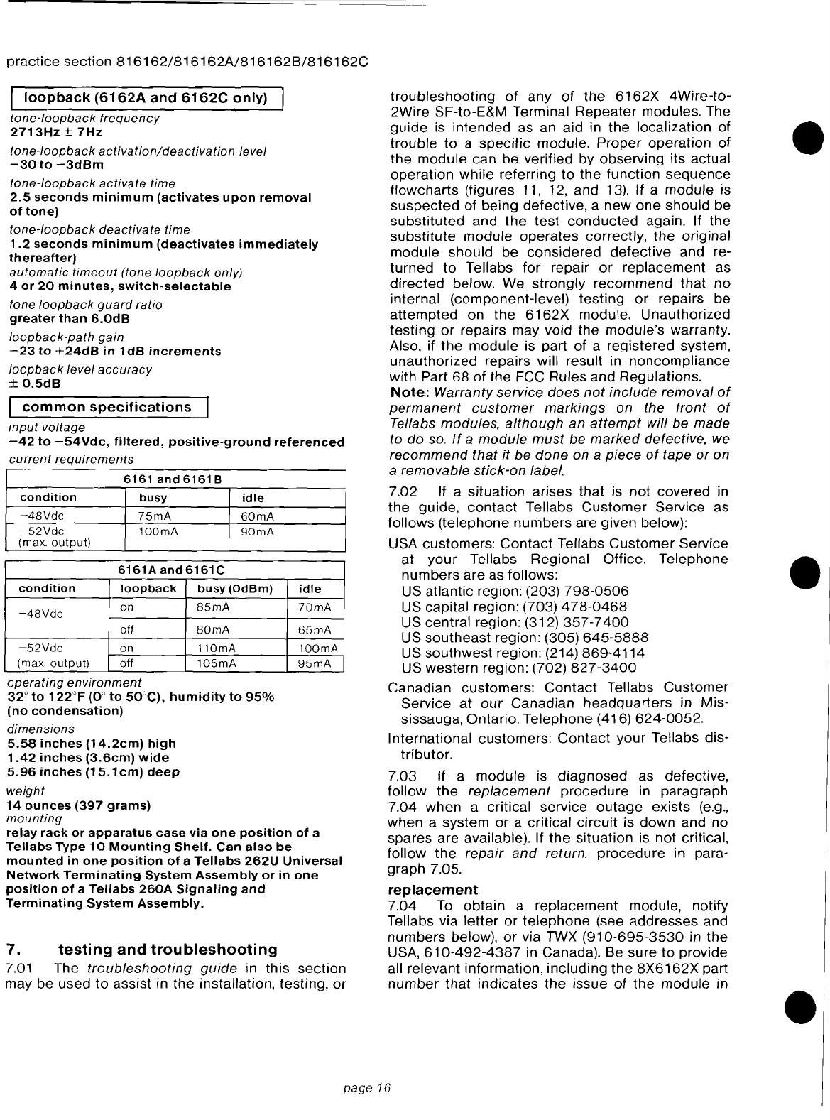
practice
section
816162/816162A/816162B/816162C
I
loopback
(6162A
and
6162C
only)
tone-Ioopback
frequency
2713Hz
±
7Hz
tone-Ioopback
activation/deactivation
level
-30
to
-3dBm
tone-Ioopback
activate
time
2.5
seconds
minimum
(activates
upon
removal
of
tone)
tone-Ioopback
deactivate
time
1.2
seconds
minimum
(deactivates
immediately
thereafter)
automatic
timeout
(tone
loopback
only)
4
or
20
minutes,
switch-selectable
tone
loopback
guard
ratio
greater
than
G.OdB
loopback-path
gain
-23
to
+24dB
in
1
dB
increments
loopback
level
accuracy
±
0.5dB
I
common
specifications
input
voltage
-42
to
-54Vdc,
filtered,
positive-ground
referenced
current
requirements
6161
and
6161 B
condition
busy
idle
-4BVdc
75mA
60mA
~52Vdc
100mA
90mA
(max.
output)
6161A
and
6161C
condition
loopback
busy
(OdBm)
idle
-4BVdc
on
B5mA
70mA
otf
BOmA
65mA
-52Vdc
on
110mA
100mA
(max.
output)
off
105mA
95mA
operating
environment
32°
to
122°F
(0°
to
50"C),
humidity
to
95%
(no
condensation)
dimensions
5.58
inches
(14.2cm)
high
1.42
inches
(3.6cm)
wide
5.96
inches
(15.1
em)
deep
weight
14
ounces
(397
grams)
mounting
relay
rack
or
apparatus
case
via
one
position
of
a
Tellabs
Type
10
Mounting
Shelf.
Can
also
be
mounted
in
one
position
of
a
Tellabs
262U
Universal
Network
Terminating
System
Assembly
or
in
one
position
of
a
Tel/abs
260A
Signaling
and
Terminating
System
Assembly.
7.
testing
and
troubleshooting
7.01
The
troubleshooting
guide
in
this
section
may be used
to
assist in the installation, testing,
or
troubleshooting
of
any
of
the
6162X
4Wire-to-
2Wire SF-to-E&M Terminal Repeater modules. The
guide
is
intended
as an aid in
the
localization of
trouble
to
a
specific
module.
Proper
operation
of
the
module
can be verified by observing its actual
operation
while
referring
to
the
function
sequence
flowcharts
(figures 11, 12,
and
13). If a
module
is
suspected
of being defective, a
new
one
should
be
substituted
and
the
test
conducted
again. If the
substitute
module
operates
correctly,
the
original
module should be
considered
defective
and re-
turned
to
Tellabs for repair
or
replacement
as
directed
below. We
strongly
recommend
that
no
internal (component-level)
testing
or
repairs be
attempted
on
the
6162X
module. Unauthorized
testing
or
repairs may void the module's warranty.
Also, if
the
module
is part of aregistered system,
unauthorized repairs will result in
noncompliance
with Part
68
of
the FCC Rules
and
Regulations.
Note:
Warranty service
does
not
include
removal
of
permanent
customer
markings
on the
front
of
Tellabs modules,
although
an
attempt
will be
made
to
do
so.
If
a
module
must
be
marked
defective, we
recommend
that
it
be
done
on a
piece
of
tape or on
aremovable
stick-on
label.
7.02 If a
situation
arises
that
is not covered in
the
guide,
contact
Tellabs
Customer
Service as
follows (telephone
numbers
are given below):
USA customers:
Contact
Tellabs
Customer
Service
at
your
Tellabs Regional Office. Telephone
numbers
are as follows:
US atlantic region: (203)
798-0506
US capital region: (703)
478-0468
US central region: (312)
357-7400
US
southeast
region: (305)
645-5888
US southwest region: (214) 869-4114
US western region: (702)
827-3400
Canadian customers:
Contact
Tellabs
Customer
Service
at
our
Canadian
headquarters
in Mis-
sissauga, Ontario. Telephone (416)
624-0052.
International customers:
Contact
your
Tellabs dis-
tributor.
7.03 If a
module
is
diagnosed
as defective,
follow
the
replacement
procedure
in paragraph
7.04 when acritical service
outage
exists
(e.g.,
when asystem
or
acritical
circuit
is
down
and
no
spares are available). If
the
situation is not critical,
follow
the
repair
and
return.
procedure
in para-
graph 7.05.
replacement
7.04
To
obtain
a
replacement
module, notify
Tellabs via
letter
or
telephone
(see addresses and
numbers
below),
or
via
TWX
(910-695-3530
in
the
USA,
610-492-4387
in Canada). Be sure
to
provide
all relevant information,
including
the
8X6162X
part
number
that
indicates
the
issue of
the
module
in
•
•
•
page
16
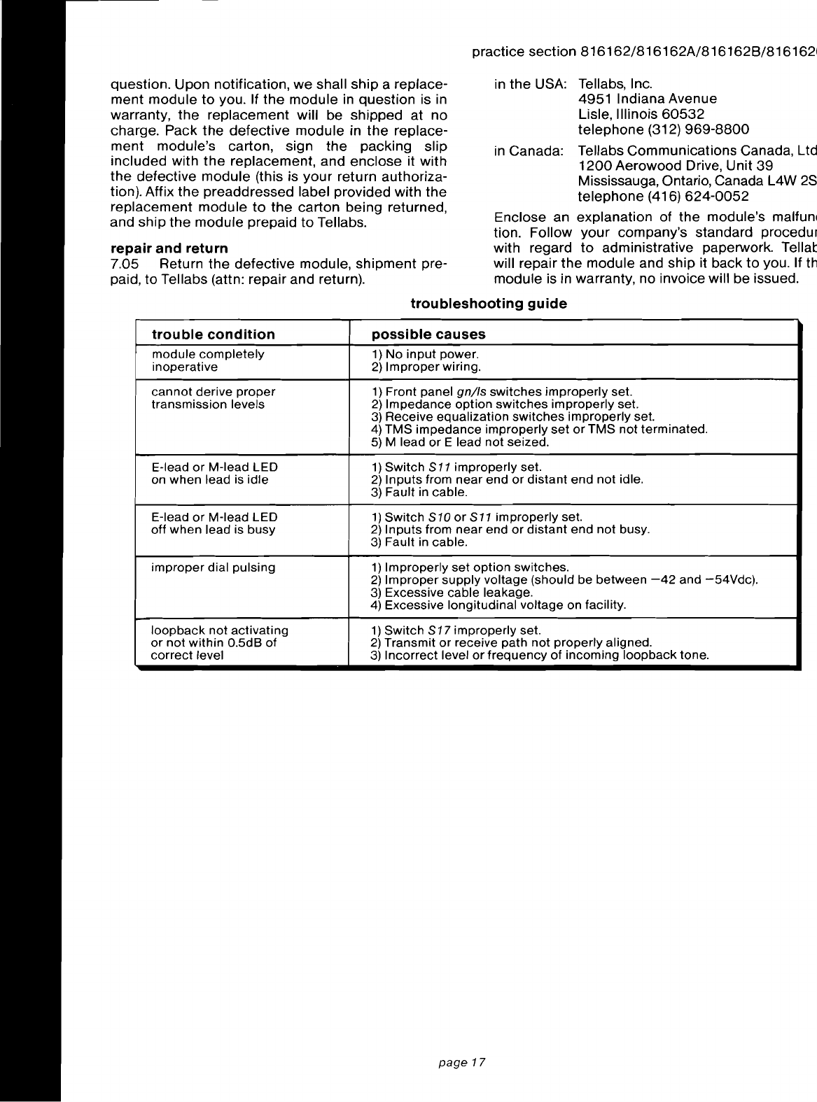
question. Upon notification,
we
shall
ship
areplace-
ment
module
to
you. If
the
module in question is in
warranty,
the
replacement will be shipped at no
charge. Pack
the
defective
module in
the
replace-
ment
module's carton, sign
the
packing slip
included with
the
replacement, and
enclose
it with
the
defective
module
(this is
your
return authoriza-
tion). Affix
the
preaddressed label provided with
the
replacement
module
to
the
carton being returned,
and ship
the
module prepaid
to
Tellabs.
repair
and
return
7.05 Return
the
defective
module,
shipment
pre-
paid, to Tellabs (attn: repair and return).
trouble
condition
module
completely
inoperative
cannot
derive
proper
transmission
levels
E-Iead
or
M-Iead
LED
on
when
lead is
idle
E-Iead
or
M-Iead
LED
off
when
lead is
busy
improper
dial
pulsing
loopback
not
activating
or
not
within
O.5dB
of
correct
level
practice section 816162/816162A1816162B/8161621
in
the
USA: Tellabs, Inc.
4951 Indiana Avenue
Lisle, Illinois
60532
telephone
(312)
969-8800
in
Canada: Tellabs Communications Canada, Ltd
1200
Aerowood Drive, Unit
39
Mississauga, Ontario, Canada L4W
2S
telephone
(416)
624-0052
Enclose an explanation of
the
module's malfunl
tion. Follow
your
company's standard procedur
with regard
to
administrative paperwork. Tellat
will repair
the
module and ship it back
to
you. If th
module is in warranty, no invoice will be issued.
troubleshooting
guide
possible
causes
1)
No
input
power.
2)
Improper
wiring.
1)
Front panel
gn/Is
switches
improperly
set.
2)
Impedance
option
switches
improperly
set.
3)
Receive
equalization
switches
improperly
set.
4)
TMS
impedance
improperly
set
or
TMS
not
terminated.
5) Mlead
or
Elead
not
seized.
1)
Switch
$11
improperly
set.
2)
Inputs
from
near
end
or
distant
end
not
idle.
3) Fault in cable.
1)
Switch
$10
or
$
11
improperly
set.
2)
Inputs
from
near
end
or
distant
end
not
busy.
3)
Fault in cable.
1)
Improperly
set
option
switches.
2)
Improper
supply
voltage
(should be
between
-42
and
-54Vdc).
3) Excessive
cable
leakage.
4) Excessive
longitudinal
voltage on facility.
1)
Switch
$17
improperly
set.
2)
Transmit
or
receive
path
not
properly
aligned.
3)
Incorrect
level
or
frequency
of
incoming
loopback
tone.
page
17
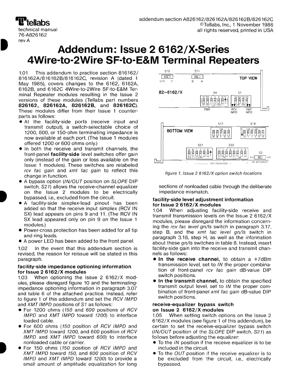
il!itellabs
technical manual
76-A826162
rev A
addendum
section
A826162/826162A/826162B/826162C
©Tellabs, Inc., 1
November
1986
all rights reserved, printed in USA
Addendum: Issue 26162/X-Series
4Wire-to-2Wire SF-to-E&M Terminal Repeaters
figure
1.
Issue 2
6162/X
option
switch locations
516
/2W
IM~'t:lljlNCF
TOP
VIEW
51
522
517
54
521
511
[]iIT]
B A
BonOM
VIEW
510
I
rn::::J
I
1/111
II
82-61621X
INT
600
2 4 8 16
IN
m~~8B~t!
rJlT9D[)~)Jf/1000--'
---------'~CB~N~~=~~~~,---------j~
sections of nonloaded cable through the deliberate
impedance
mismatch.
facility-side
level
adjustment
information
for
Issue
2
6162/X
modules
1.04 When adjusting facility-side receive and
transmit
transmission levels on the Issue 2
6162/X
modules, please disregard the information concern-
ing
the
rev fae level
gn/Is
switch in paragraph 3.17,
step
B,
and
the
xmt
fae level
gn/Is
switch in
paragraph 3.18,
step
H,
as well as
the
information
about
these
gn/Is
switches
in table
8.
Instead, insert
facility-side gain
into
the
receive and transmit chan-
nels as follows:
•In
the
receive
channel,
to obtain a
+7dBm
transmission level,
set
to
IN
the
proper
combina-
tion
of
front-panel rev fae
gain
dB-value DIP
switch
positions.
•In
the
transmit
channel,
to
obtain
the
specified
transmit
output
level,
set
to
IN
the
proper com-
bination
of
front-panel
xmt
fae
gain
dB-value DIP
switch
positions.
receive-equalizer
bypass
switch
on
Issue
2
6162/X
modules
1.05 When
setting
switch
options
on the Issue 2
6162/X
modules
(see figure 1
of
this addendum), be
certain
to
set
the
receive-equalizer bypass switch
(IN/OUT
position of
the
SLOPE
DI
Pswitch, S21) as
follows before adjusting
the
equalizer:
•
To
the
IN
position if
the
receive equalizer is
to
be
included
in the circuit.
•
To
the
OUT
position if the receive equalizer is to
be
excluded
from
the
circuit,
i.e.,
electrically
bypassed.
1.01
This
addendum
to
practice
section
816162/
816162A/816162B/816162C,
revision A(dated 1
May
1985), covers
changes
to
the
6162, 6162A,
6162B, and
6162C
4Wire-to-2Wire
SF-to-E&M Ter-
minal
Repeater
modules
resulting in
the
Issue 2
versions of
these
modules
(Tellabs
part
numbers
826162,
826162A,
8261628,
and
826162C).
These
modules
differ
from
their
Issue 1
counter-
parts
as follows:
•
At
the
facility-side
ports
(receive
input
and
transmit output), a
switch-selectable
choice
of
1200,600,
or
150-ohm
terminating
impedance
is
now
available at each port. (The Issue 1
modules
offered
1200
or
600
ohms
only.)
•
In
both
the
receive and transmit channels,
the
front-panel
facility-side
level
switches
offer
gain
only (instead
of
the
gain
or
loss available on
the
Issue 1modules). These
switches
are
relabeled
rev fae
gain
and
xmt
fae
gain
to
reflect
this
change
in function.
• A bypass
option
(IN/OUT
position on
SLOPE
DIP
switch, S21) allows
the
receive-channel
equalizer
on
the
Issue 2
modules
to
be
electrically
bypassed,
i.e.,
excluded
from
the
circuit.
• A facility-side simplex-lead
pinout
has been
added
so
that
the
receive
input
simplex
(RCV IN
SX)
lead appears on pins 9
and
11. (The RCV IN
SX lead
appeared
only
on pin 9on
the
Issue 1
modules.)
•Power-cross
protection
has been
added
for all
tip
and ring leads.
• A
power
LED has been
added
to
the
front
panel.
1.02
In
the
event
that
this
addendum
section
is
revised,
the
reason
for
reissue will
be
stated
in
this
paragraph.
facility-side
impedance
optioning
information
for
Issue
2
6162/X
modules
1.03 When
optioning
the
Issue 2
6162/X
mod-
ules, please disregard figure 10 and the terminating-
impedance
optioning
information in paragraph 3.07
and table 6
of
the
attached
practice. Instead, refer
to
figure 1
of
this
addendum
and
set
the
RCV
IMPD
and
XMT
IMPD
positions
of
S1
as follows:
•For
1200
ohms
(150
and
600
positions
of
RCV
IMPD
and
XMT
IMPD
toward
1200)
to
interface
loaded cable.
•For
600
ohms (150 position
of
RCV
IMPD
and
XMT
IMPD
toward 1200,
and
600
position
of
RCV
IMPD
and
XMT
IMPD
toward 600)
to
interface
nonloaded cable
or
carrier.
•For
150
ohms
(150 position
of
RCV
IMPD
and
XMT
IMPD
toward
150,
and
600
position
of
RCV
IMPD
and
XMT
IMPD
toward
1200)
to
provide a
small
amount
of
amplitude
equalization
for
long
This manual suits for next models
3
Table of contents


