tempLED RayLite Pro Series User manual

MONTAGEANLEITUNG
INSTALLATION GUIDE
tempLED RayLite Pro 75 - 180
tempLED GmbH
V.01/2020
Modulares LED-Hallenleuchtensystem
Modular LED highbay lighting system

© tempLED GmbH |Marmorwerkstraße 52 |83088 Kiefersfelden |Deutschland
MONTAGEANLEITUNG
tempLED RayLite Pro Serie
Allgemeine Sicherheitshinweise
INSTALLATION GUIDE
tempLED RayLite Pro series
General safety notes
Vorsicht!
Gefahr eines elektrischen Schlages!
Montage und Inbetriebnahme der Leuchte nur
durch autorisierte Fachkräfte. Vor jeder Arbeit
an der Leuchte die Stromzufuhr unterbrechen
und gegen versehentliches Wiedereinschalten
sichern. Die Leuchte darf nur mit vollständigem
und unbeschädigtem Gehäuse in Betrieb genom-
men werden. Die Stromzufuhr ist mit geeigneten
Maßnahmen (Fehlerstrom-Schutzschalter o.ä.)
abzusichern.
Caution!
Risk of electric shock!
Mounting and installation of the luminaire only
by authorized personnel. Disconnect the power
supply and protect it from restarting by mistake
before working on the luminaire. The lumin-
aire must only be operated with complete and
undamaged housing. Please secure the main
power by means of suitable measures, for ex-
ample a residual current circuit breaker.
1
Vorsicht!
Absturzgefahr!
Bei der Montage der Leuchte ist darauf zu
achten, dass das gewählte Montagematerial
(Schrauben, Dübel) sowie die Dimensionen von
Bohrlöchern und Schrauben für das Gewicht der
Leuchte und die Beschaenheit und Tragfähig-
keit der Montageoberäche geeignet ist.
Keine Haftung für fehlerhaft ausgeführte Monta-
ge, unsachgemäßen Betrieb oder Veränderun-
gen an der Leuchte!
Caution!
Danger of falling!
Please use suitable mounting material (screws,
wall plugs) and dimensions for the drilling holes
and screws. They must be suitable for the weight
of the luminaire as well as the composition and
bearing capacity of the mounting location. No
liability for damages resulting from improper
installation, inexpert operation or modication of
the luminaire!
2
Lieferumfang:
- Montagehaken mit
Sicherungsschraube
Package contents:
- Mounting hook with
locking screw
3
V.01/2020

© tempLED GmbH |Marmorwerkstraße 52 |83088 Kiefersfelden |Deutschland
MONTAGEANLEITUNG
tempLED RayLite Pro Serie
Montagehaken
INSTALLATION GUIDE
tempLED RayLite Pro series
Mounting hook
Schritt 1:
Netzkabel einfädeln
Önen Sie die Sicherungsschraube am
Montagehaken.
Fädeln Sie das Netzkabel der Leuchte
durch die Önung am Montagehaken.
Step 1:
Threading the power cable
First, open the locking screw of the
mounting hook.
Then thread the power cable of the
luminaire through the opening of the
mounting hook.
1
Schritt 2:
Montagehaken eindrehen
Drehen Sie den Montagehaken mit
dem kompletten Gewinde in die dafür
vorgesehene Önung auf der Rücksei-
te der Leuchte ein und fest.
ACHTUNG - QUETSCHGEFAHR!
Achten Sie darauf, dass das Kabel sich
nicht verdreht oder gequetscht wird.
Step 2:
Screw in the mounting hook
Screw the mounting hook with the
complete thread into the intended
opening on the backside of the lumin-
aire and tighten the mounting hook.
CAUTION - DANGER OF PINCHING!
Please be sure not to jam or pinch any
cable during the screwing process.
2
Schritt 3:
Sicherungsschraube schließen
Drehen Sie die Sicherungsschraube
am Fuss der Önung für den Monta-
gehaken mit einem Inbusschlüssel der
Größe 3 fest.
Step 3:
Tighten the locking screw
Tighten the locking screw on the foot
of the opening for the mounting hook
by using an Allen key size 3 or a hex
wrench size 3.
3
V.01/2020

© tempLED GmbH |Marmorwerkstraße 52 |83088 Kiefersfelden |Deutschland
MONTAGEANLEITUNG
tempLED RayLite Pro Serie
Montagehaken
INSTALLATION GUIDE
tempLED RayLite Pro series
Mounting hook
Schritt 4:
Maße des Montagehakens
DIe genauen Maße des Montage-
hakens sind in der nebenstehenden
Maßzeichnung ersichtlich.
Step 4:
Measurements of the mounting hook
For detailed dimensions of the mount-
ing hook, please use the dimension
drawing on the left.
23 mm
35 mm
85 mm
25 mm 40 mm 20 mm
4
Schritt 5:
Abhängung einführen
Führen Sie nun ihre bauseits vorhan-
dene Abhängung in den Montagehaken
ein.
(Beispielabbildung hier mit Kettenab-
hängung)
Step 5:
Install suspension
Introduce your on-site suspension into
the mounting hook.
(Symbol picture on the left with chain
suspension)
5
Schritt 6:
Sicherungsschraube schließen
Drehen Sie die Sicherungsschraube
des Montagehaken mit einem Inbus-
schlüssel der Größe 3 komplett ein und
fest.
(Beispielabbildung hier mit Kettenab-
hängung)
Step 6:
Tighten the locking screw
Close and tighten the locking screw of
the mounting hook by using an Allen
key size 3 or a hex wrench size 3.
(Symbol picture on the left with chain
suspension)
6
V.01/2020
© tempLED GmbH |Marmorwerkstraße 52 |83088 Kiefersfelden |Deutschland
MONTAGEANLEITUNG
tempLED RayLite Pro Serie
Bügelmontage
INSTALLATION GUIDE
tempLED RayLite Pro series
Surface mounting
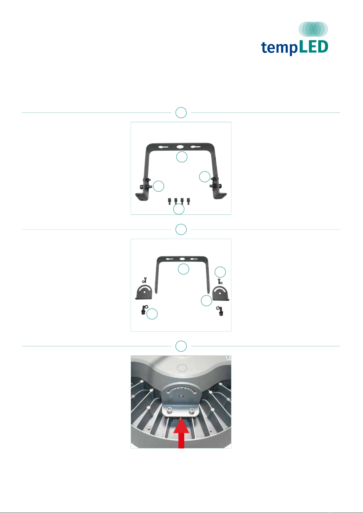
Schritt 1:
Lieferumfang Montagebügel
(Sonderzubehör)
- 1x Montagebügel [1] mit
2x Halteplatten [2]
- 2x Halteschrauben mit Mutter [3]
- 2x Feststellschrauben für die
Winkelverstellung mit Mutter [4]
- 4x Montageschrauben [5]
Step 1:
Package contents
(additional accessories)
- 1x Mounting bracket [1] with
2x Holder plates [2]
- 2x Holder screws with nut [3]
- 2x Locking screws for
angle adjustment with nut [4]
- 4x Mounting screws [5]
1
Schritt 2:
Montagebügel zerlegen
Der Montagebügel wird in der Regel
vormontiert geliefert und muss vor
der Montage zerlegt werden. Achten
Sie darauf, keine Beilagscheiben und
Abstandshalter zu verlieren.
Sie brauchen:
- Inbusschlüssel der Größe 5,5 und 6
- Ringschlüssel der Größe 10 und 13
Step 2:
Dismantle the holder
By default, the mounting bracket will
be delievered pre-installed and has to
be dismantled before mounting. Please
be careful not to lose any washers and
spacers.
You need:
- Allen key / hex wrench size 5,5 and 6
- Ring spanner size 10 and 13
2
Schritt 3:
Erste Halteplatte anbringen
Schrauben Sie die erste Halteplatte [2]
des Montagebügels wie auf dem Bild
rechts dargestellt mit den Schrauben
nach aussen mit Hilfe der mitgeliefer-
ten Montageschrauben [5] und einem
Inbusschlüssel der Größe 4 an der
Leuchte fest.
Vergessen Sie die Abstandshalter
nicht.
Step 3:
Mounting rst holder plate
Screw the rst holder plate [2] of the
mounting bracket onto the luminaire as
shown on the picture to the left - with
the screws pointing outside. Do so by
using the included mounting screws
[5] and an Allen key size 4 or a hex
wrench size 4.
Do not forget the spacers.
3
V.01/2020
1
1
3
3
4
4
5
2

© tempLED GmbH |Marmorwerkstraße 52 |83088 Kiefersfelden |Deutschland
MONTAGEANLEITUNG
tempLED RayLite Pro Serie
Bügelmontage
INSTALLATION GUIDE
tempLED RayLite Pro series
Surface mounting
Schritt 4:
Zweite Halteplatte anbringen
Schrauben Sie die zweite Halteplatte
[2] des Montagebügels wie auf dem
Bild rechts dargestellt mit den Schrau-
ben nach aussen mit Hilfe der mitge-
lieferten Montageschrauben [5] und
einem Inbusschlüssel der Größe 4 an
der Leuchte fest.
Vergessen Sie die Abstandshalter
nicht.
Step 4:
Mounting second holder plate
Screw the second holder plate [2] of
the mounting bracket onto the luminaire
as shown on the picture to the left -
with the screws pointing outside. Do so
by using the included mounting screws
[5] and an Allen key size 4 or a hex
wrench size 4.
Do not forget the spacers.
4
Schritt 5:
Anzeichnen der Bohrlöcher
Zeichnen Sie die Bohrlöcher an der
Oberäche des Montageortes an.
Nehmen Sie dazu die nebenstehende
Masszeichnung zur Hilfe.
Step 5:
Marking the drill holes
Mark the drill holes on the surface of
the mounting location. Please use the
measurement drawing on the left.
33,00 mm 23,00 mm 33,00 mm
50,00 mm 50,00 mm
100,00 mm
40,00 mm
205,00 mm
10,00 mm
15,00 mm
5
Schritt 6:
Bohrlöcher anfertigen
Prüfen Sie ggf. die Stellen der Bohrlö-
cher mit einem Leitungssuchgerät und
fertigen Sie dann die Bohrlöcher an.
Wählen Sie einen der Montageober-
äche und dem Gewicht der Leuchte
angepassten Bohrlochdurchmesser.
(Symbolabbildung)
Step 6:
Drilling the holes
Please check the drilling spots with a
line locator and drill the holes. Choose
a drill hole diameter suitable for the
material of the mounting surface and
the weight of the luminaire.
(symbol illustration)
Leitungssuchgerät
Line locator
ON / OFF
6
V.01/2020
Driller icon made by Freepik from www.aticon.com
© tempLED GmbH |Marmorwerkstraße 52 |83088 Kiefersfelden |Deutschland
MONTAGEANLEITUNG
tempLED RayLite Pro Serie
Bügelmontage
INSTALLATION GUIDE
tempLED RayLite Pro series
Surface mounting
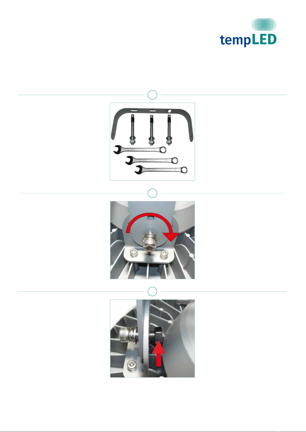
Schritt 7:
Montieren des Bügels
Montieren Sie den Bügel mit geeig-
netem Schraubenmaterial für die Mon-
tageoberäche und dem Gewicht der
Leuchte. Wir empfehlen den Einsatz
von Edelstahlschrauben.
(Symbolabbildung)
Step 7:
Mounting the bracket
Screw the mounting bracket to the
surface. Use screw material suitable for
the mounting surface and the weight
of the luminaire. We recommend
high-grade steel screws and mounting
material.
(symbol illustration)
7
Schritt 8:
Montieren der Leuchte 1
Montieren Sie die Leuchte an den
Montagebügel und drehen Sie dazu die
beiden Halteschrauben [3] zur Hälfte
per Hand ein.
Vergessen Sie die Abstandshalter und
Beilagscheiben nicht.
Step 8:
Mounting the luminaire 1
Mount the luminaire on the bracket
by manually tightening the two holder
screws half way [3] .
Do not forget the spacers and washers.
8
Schritt 9:
Montieren der Leuchte 2
Setzen Sie jeweils die passende Mutter
auf die Halteschrauben auf, drehen Sie
die Halteschrauben per Hand komplett
ein und ziehen Sie beides mit Hilfe
eines Inbusschlüssels der Größe 6 und
eines Ringschlüssels der Größe 13
fest.
Wir empfehlen ein Drehmoment von
maximal 7,5 Nm.
Step 9:
Mounting the luminaire 2
Put the suitable nut onto each holder
screw, manually screw in the holder
screws completely and tighten both
by using an Allen key size 6 or a hex
wrench size 6 and a ring spanner size
13.
We recommend a maximum torque of
7.5 Nm.
9
V.01/2020

© tempLED GmbH |Marmorwerkstraße 52 |83088 Kiefersfelden |Deutschland
MONTAGEANLEITUNG
tempLED RayLite Pro Serie
Bügelmontage
INSTALLATION GUIDE
tempLED RayLite Pro series
Surface mounting
Schritt 10:
Winkel einstellen 1
Stellen Sie den gewünschten Winkel
ein und setzen Sie anschließend die
beiden Feststellschrauben [4] der Win-
kelverstellung zur Hälfte ein.
Step 10:
Angle adjusting 1
Adjust the luminaire angle according to
your specic needs and put in the two
locking screws [4] of the angle adjust-
ment half way.
10
Schritt 11:
Winkel einstellen 2
Setzen Sie jeweils die passende Mutter
auf die Feststellschrauben der Winkel-
verstellung auf und ziehen Sie beides
mit Hilfe eines Inbusschlüssels der
Größe 5,5 und eines Ringschlüssels
der Größe 10 fest.
Step 11:
Angle adjusting 2
Put the suitable nut onto each locking
screw of the angle adjustment and
tighten both by using an Allen key size
5,5 or a hex wrench size 5,5 and a ring
spanner size 10.
11
V.01/2020

© tempLED GmbH |Marmorwerkstraße 52 |83088 Kiefersfelden |Deutschland
MONTAGEANLEITUNG
tempLED RayLite Pro Serie
Elektrische Anschlüsse
INSTALLATION GUIDE
tempLED RayLite Pro series
Electrical power connections
Schritt 1: Vorsicht!
Gefahr eines elektrischen Schlages!
Montage und Inbetriebnahme der Leuchte nur
durch autorisierte Fachkräfte. Vor jeder Arbeit
an der Leuchte die Stromzufuhr unterbrechen
und gegen versehentliches Wiedereinschalten
sichern.
Step 1: Caution!
Risk of electric shock!
Mounting and installation of the luminaire only
by authorized personnel. Disconnect the power
supply and protect it from restarting by mistake
before working on the luminaire.
1
Schritt 2:
Kombikabel
Die tempLED RayLite Pro Serie ver-
wendet ein Kombikabel sowohl für den
Netz- als auch für den DALI-Anschluß.
Die Adernbelegung ist in Schritt 3
dargestellt.
Isolieren Sie nicht verwendete Adern
fachgerecht gegen Kurzschluss.
Step 2:
Combined cable
The tempLED RayLite Pro series uses
a combined cable for electrical con-
nection and for DALI-connection. For
wiring, please check step 3.
Do not forget to isolate all unused wires
professionally to prevent short circuits.
2
Schritt 3:
Adernbelegung
Die Adernbelegung des Kombikabels
lautet wie folgt:
Phase [L] - braun
Schutzleiter (Erdung) - gelb/grün
Neutralleiter [N] - blau
DALI - grau
DALI - violett
Step 3:
Wiring
The wiring of the power cable is as
follows:
Power conductor [L] - brown
Protective conductor - yellow/green
Neutral conductor [N] - blue
DALI - grey
DALI - purple
DALI
DALI
N
L
3
V.01/2020

© tempLED GmbH |Marmorwerkstraße 52 |83088 Kiefersfelden |Deutschland
MONTAGEANLEITUNG
tempLED RayLite Pro Serie
Anhang
INSTALLATION GUIDE
tempLED RayLite Pro series
Appendix
V.01/2020
Technische Basisdaten: Basic technical data:
Spannungsversorgung 100 - 240 V~ / 50 - 60 Hz Power input
Maximaler Einschaltstrom 60 A Maximum inrush current
Schutzart IP65 Protection class
Produkthöhe 181 mm Height of the luminaire
Produktdurchmesser 350 mm Diameter of the luminaire
Maximales Produktgewicht 4300 g Maximum weight of the luminaire
Technische Änderungen vorbehalten. Specications are subject to change
without notice.
Montagezubehör: Mounting accessories:
Montagebügel 932151 Luminaire holder
Montagebügel Edelstahl 932153 Luminaire holder stainless steel
Masthalter für Mastaufsatz 932165 Pole mounting set
Halterohr für Stabmontage 1,00m 932162 Support tube 1,00m for rod assembly
Halterohr für Stabmontage 1,50m 932163 Support tube 1,50m for rod assembly
Halterohr für Stabmontage 2,00m 932164 Support tube 2,00m for rod assembly
Kran-Montage-Kit 932810 Crane mounting set
Seilabhängung 932161 Suspend cable
This manual suits for next models
4
Other tempLED Light Fixture manuals

Popular Light Fixture manuals by other brands

Dialight
Dialight DUROSITE LPM3C4D2P Installation and maintenance manual

Cooper Lighting
Cooper Lighting Combolight LV3050IS Specification sheet

Toro
Toro Twilight TWGC Setup guide

ANP Lighting
ANP Lighting Madison installation instructions

Cooper Lighting
Cooper Lighting Corelite 2T8 Specifications

Chauvet
Chauvet DL-LEDW user manual

Harman
Harman Martin ERA 600 Performance user guide

American DJ
American DJ Colorbar 39 user guide

involight
involight MovingBAR2410Q user manual

California Accent Lighting
California Accent Lighting lipLED LLED8200-ST installation instructions

Briloner
Briloner 2633054 Mounting instructions

STARVILLE
STARVILLE MH-X50+ user manual


