CALIFORNIA ACCENT LIGHTING, INC.
2034 E. Lincoln Ave. #431, Anaheim, CA 92806
ph. 800.921.CALI (2254) or 714.535-7900 \ fx. 714.535.7902
© CALI. All rights reserved. CALI reserves the right to make changes or withdraw specications without prior notice.
Installation Instructions Overview
lipLED™LLED8200-ST
2 of 11
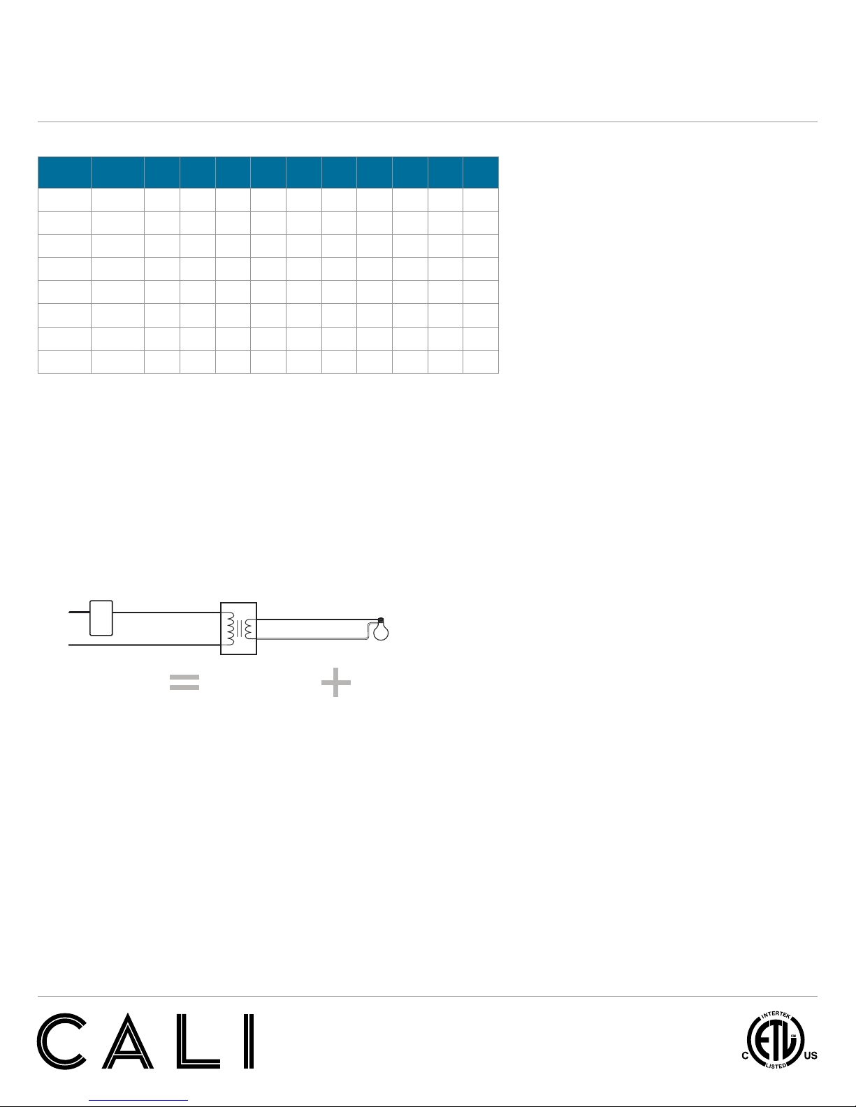
Symmetric Forward Phase-Control
DIMMING PROTOCOL (Forward Phase Dimming)
Technical Requirements for Control Equipment (Forward Phase Dimming)
• Magnetic Low Voltage (MLV) - Magnetic (core and coil, toroidal)
transformer-supplied low voltage lighting.
• Electrical Characteristics - Inductive
• Special Requirements - Symmetric cycles
(VDC≤2), smooth turn off (positive and negative
periods are equal for safe MLV transformer operation)
• Order transformer with TRA prefix.
DIMMING PROTOCOL (0-10V)
LipLEDs are available in 120 or 277 volts with a dimmable remote driver.
The remote driver is available with 0-10V dimming capabilities.
The following applies to 0-10V dimming interfaces. A 0-10v fluorescent
dimmer will not dim the LEDs.
Technical Requirements for Control Equipment (0-10V Protocol)
• The output current level of the dimmable driver is controlled by DC
voltage (0-10V) applied to the control terminals (blue and white).
The light output of LEDs is controlled by the amount of output current
from the dimmable driver.
• The control device must be capable of sinking a DC current flow from
the driver. The maximum amount under any condition is 500
microamps (uA) per driver.
• The control terminals of the dimmable driver are isolated from the
power lines and are suitable for use as Class 2 wiring. Multiple drivers
are desired for use with same control device, the control terminals may
be connected in parallel in a bus configuration.
• Since the control bus is Class 2 wiring, all control devices that are
connected to the power line must have proper isolation between the
power line and the control terminals/bus.
• The control device, which intends to control more than one dimmable
driver, must be capable of sinking the total current supplied to control
bus by the drivers.
• If the control terminals/bus is shorted in any case, the current on the
control terminals/bus will be 500 microamps (uA) per driver maximum.
• If the control terminals are opened, the voltage on the control terminals
will then be 10V ± 0.5 volt. As a result, dimmable driver supplies
maximum output current to LEDs under this condition.
• The driver is intended for use with control voltages between 0 and 10VDC.
The control equipment must not impose a voltage greater than 11 V peak
maximum on the driver control terminals.
• Order transformer with TRA-E prefix.
(TRA-E) 0-10V Dimming
(TRA) Forward Phase Dimming
*Maximum run is based on 5 Amps: 20’ (6W), 30’ (4W), 36’ (2W)
For class II applications: 14’ (6W), 24’ (4W), 36’ (2W)
FEATURES
APPLICATIONS Accent, Decorative Lighting
VOLTAGE 24VDC
LAMP TYPE Modular LEDs
DIMMING Forward Phase (TRA)
0-10V (TRA-E)
Hi-Lume 1% A Series (2 Wire)
Hi-Lume 1% (3 Wire)
LENGTH Built to Order
CONSTRUCTION LED Modules
(Field Cuttable - Dry Location Only)
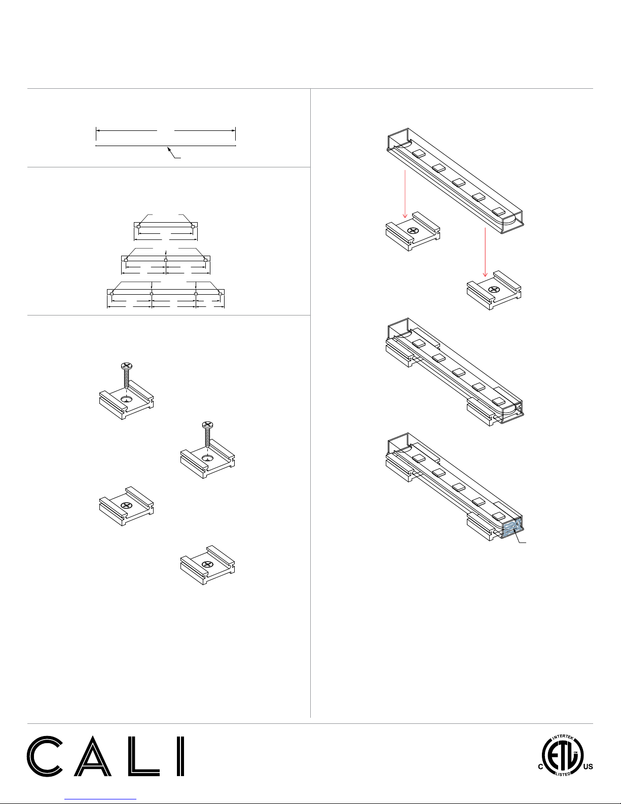
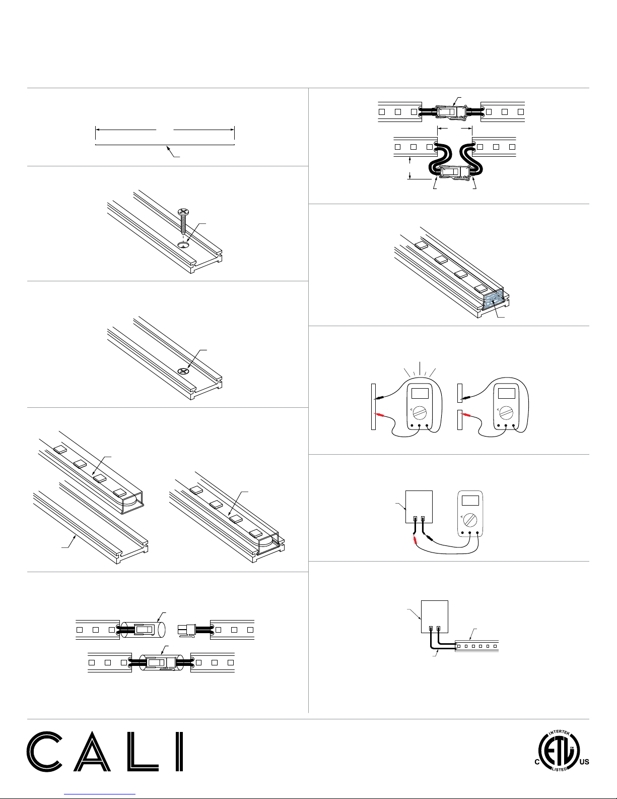
MOUNTING Mounting Clips or Mounting Channel
CRI >90
EFFICACY 108 Lumens per Watt
VIEWING ANGLE 120 Degrees
L70 LED LIFE 60,000 hrs.
MAXIMUM RUN* 20’ (6W), 30’ (4W), 36’ (2W)
LISTING Dry or Wet (IP65 or IP67) Location
UL2108, CSA C22.2#9
UL8750, CSA250
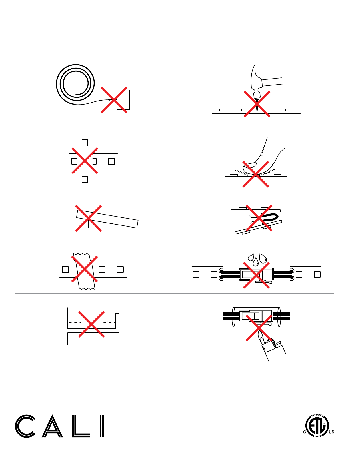
WARNING
When using lipLEDs for any application, basic safety precautions
should always be followed to reduce the risk of fire, electric shock,
and personal injury. lipLEDs must be installed in accordance with
the NEC or CEC as applicable. CALI will not be responsible for any
damage or malfunction caused by the following:
• Do not exceed maximum length per circuit. Each maximum run requires
additional power feed from the transformer
• Do not cover lipLEDs as the covering may cause it to overheat, melt, or ignite.
• Do not install lipLEDs in hazardous locations or closer than 6 inches
from any curtain or similar combustible material.
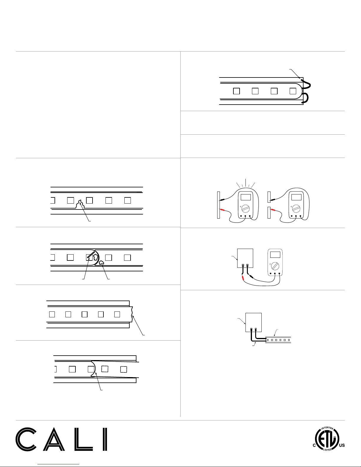
• Do not use lipLEDs if damaged, such as broken outer jacket, loose
connections, or frayed wire insulation. Inspect periodically.
• Do not submerge lipLEDs in liquid.
• Do not mount lipLEDs with staples, nails, or like means that might
damage the insulation. Mount with double-sided tape and mounting clips.
• Do not install lipLEDs in places where it is subject to continuous flexing.
• Do not mount lipLEDs inside tanks or enclosures of any kind without
sufficient ventilation.
• Ground Fault Circuit Interrupter (GFCI) protections are required
on circuits or outlets.
• Surge protector must be set up for electrical power system to avoid
damaging lipLEDs lighting system.
• Do not install in an environment where excessive heat may exist.
Ambient temperature -40°F - 122°F (-20°C - 50°C).
• Only wet location models are intended for outdoors. See package label
for environmental details.
• Do not install wet location model in areas where water will collect.
• Do not modify wet location extrusion, end caps, or power connectors.