TS35-U06 / Rev. 00/22.06.12
TS35 |3
1. General Precautions
Please read the rules in this Section carefully; to
avoid the risk of death, injury or property dam-
age. Qualied and trained technicians should
use The Service Bulletin. Making repairs or ser-
vice without the adequate training and using
inappropriate tools and equipment may cause
injury and could damage the bus. Some of the
procedures require specic tools designed for
specic purposes, so use the tools mentioned
in the manual when necessary.
Bus service and repair must be done correctly
following the instructions to ensure the safety
of the service technician and correct function
of the bus. If a part must be replaced, the same
part number or an equivalent part should be
used. Pay great attention to use a replacement
part of good quality.
2. Symbol List
Operating Instructions in this bulletin includes
the folowing symbols, warning words and signs:
CAUTION
This symbol is used in conditions which may cause dam-
age or injury if necessary measures are not taken.
WARNING
This symbol is used in conditions which may cause se-
vere damage or fatal injury if necessary measures are
not taken.
DANGER
This symbol is used to indicate danger.
VISUAL INSPECTION
This symbol is used to inform the user that a visual
inspection is necessary.
3
6
912
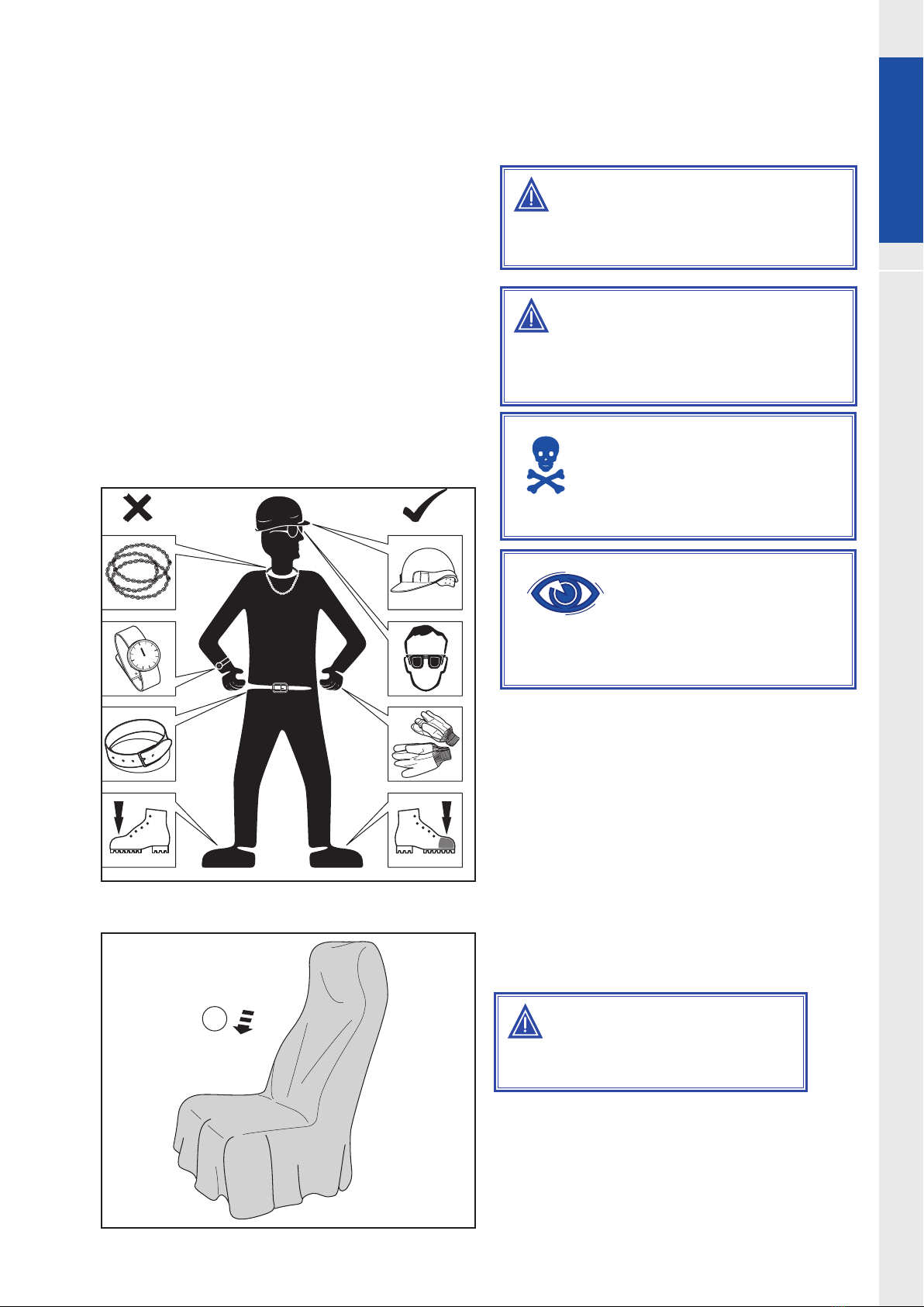
3. Before Start of Work
3.1. Mechanical Requested Dress Code
Always wear protective clothing. Do not
wear any damaged or loose-tting cloth-
ing and remove jewelry before starting
the work. In case of long hair use hairnet.
The illustration below shows some of the
correct on incorrect clothing that should
been worn during work.
Sharp edges should be avoided e.g belts,
watches, necklaces to prevent scatching
the vehicle.
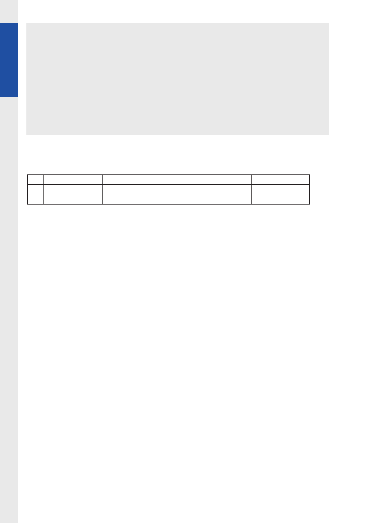
3.2. Protect Seats When
Mechanics Start Working
1. Seats, trimming, upholstery stuff and car-
peting should be protected with appropri-
ate coverings.
WARNING
Dress correctly to avoid injury and damage to
the vehicle.