Date Page
1-2
MC-9
MAINTENANCE
MANUAL
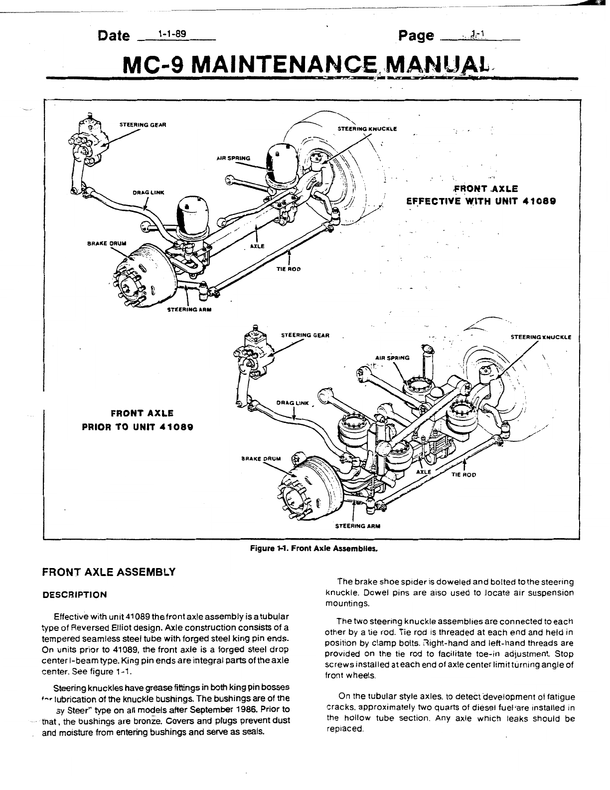
Steering
knuckles
are bushed in the
upper
and
lower
pm
bosses
so
thatthey mayturn fr:eel¥.about the pins. Bushings
are
grooved
on
the inside to
allow
grease to flow uniformly to
high-pressure
areas. Grease
fittings
areinstalled
at
both
upper
and
lower
king pin bosses.
On
the
earlierMC-9
front
axles
the
tapered
steering
knuckle
pins are
drawn
into
the
axle
center
by
tightening
the
nut
at
the
upper
end
of
the
pin. Onthe laterMC•9s a
straight
type
knuckle
pin is used.
The
straighttype pin
i~
held
in
placeby
draw
keys
in
the knuckle. "
Wheel bearings. air suspension. steering and brake parts
which
are
mounted
on thefrontaxlearedescribe<;l in
the
appli-
cable
sections
of this manual.
LUBRICATION
Periodic
lubrication
according
to the recommendations in
the
lubrication
section of this manual should
be
carried out.
Points
which
require lubrication are the steering
knuckle
pins.
tie-rod
ends
and drag link ends. These are
provided
with
grease fittings for pressure lubrication.
MAINTENANCE
Periodic
mspection
of the front axle assembly
should
be
made
to
see that all. bolts are tight and that
no
damage or
distortion
has taken place. Suspension support stud nuts.
U-bolt
nuts.
tie-rod
armand steering arm nuts. and stop
screws
should
be
checked
and tightened
1f
necessary to the torque
specifications
shown
at
the end
of
this section.Attention
should
also
be
given
·to
the
condition
of the steering
knuckle
pin
and
bushings.
If excessive looseness
is
found• at
this
point. the
bushings
and
pins should be replaced.
The
axle
manufacturer recommends that the
bronze
or
"Easy
Steer"
king
pin
bushings
be
replaced
when
the range
of
side-to-side
tire movement reaches
.030
inch
or
when the
bushings
are
worn
to amaximumof .010
inch
on their diameter.
NOTE:
These measurementsaremade with
thewheel bearingstightened on
the
spindle.
With
new
bushings
installed. the range of
side-to-side
tire
movement
should
not exceed .010 inch maximum. Refer to
Figure 1-2.
Looseness
in the steering linkage
under
normal steering
toads is
sufficient
cause to immediately
check
all
pivot
pomts
tor wear. regardless of accumulated m!leage. Steering
linkage
p,vot
points
should
be checked each time the axle assembly
,s
lubricated.
If
any
1nd1cat1on
of
lateral movement is found.
cross
tube
ends
should
be removed for inspection. Looseness
at
the
steering
linakge
pivot points can be visually detected
during
movement of the ven1cle steering wheel.
Steering knuckles. king pins. and
bushings
may
be
replaced
without
removing the axle from the coach.
.010 INCH MAX.
SIDE-TO-SIDE
TIRE MOVEMENT
FRONT
OF TIRE
NEW
BUSHINGS
.030
INCH
MAX.
SIDE-TO-SIDE
TIRE MOVEMENT
(OR BUSHING
DIAMETER
WORN .010")
..,&.-·----
FRONT OF TIRE
WORN
BUSHINGS
Figure 1-2. Side-To-Side
Tire
Movements With New And
With Worn King Pin Bushings.
If extensive overall
work
or
straightening of
the
front
axle
center
,s
necessary. the axle should. of course. be removed.
WARNING:
Do not attempt to repair,
remove or reinstall front axle with the vehi-
cle supported by jacks only.
FRONT
AXLE REMOVAL (Prior to
unH
41089)
To
remove the entire
front
axle assembly first
block
the
rear
wheelsto preventthevehiclefrom rolling.Raisethe frontend
of
the
coach
with jacks until
the
bottom of the
coach
body is
approximately
18"
(45
7.2
mm) from the floor.
Block
the body in
this position as indicated in Section 3
under
Coach
Jacking
Points.
CAUTION:
Do not raise the body in such a
way that the entire weight of the front axle
will hang on the suspension bellows
assemblies. Damage to the bellows may
result.