Tera 2I612CW User manual

2I612CW
Intel Skylake-U / Kaby Lake-U Core i CPU,
DDR4 2133 MT/s SODIMM, 2 x LAN / 2 x HDMI / USB /
COM / PCIe mini card
All-In-One
Intel Skylake-U / Kaby Lake-U Core i CPU,
2 x Intel GbE LAN, 2 x PCIe mini card slots, 2 x HDMI, eDP,
4 x USB 3.0, 3 x USB 2.0, 2 x COM, Wide Range DC-IN
NO. 2I612CW
Release date: Feb. 18. 2020
RISK OF EXPLOSION IF BATTERY IS REPLACED
BY AN INCORRECT TYPE.
DISPOSE OF USED BATTERIES ACCORDING
TO THE INSTRUCTIONS
CAUTION

i
2I612CW
Warning!...........................................................................................................................
Hardware Notice Guide .............................................................................................
CHAPTER 1 GENERAL INFORMATION ........................................................................
1-1 MAJOR FEATURE........................................................................................................
1-2 SPECIFICATION ..........................................................................................................
1-3 INSTALLING THE SO-DIMM ........................................................................................
1-3-1 REMOVING THE SO-DIMM ......................................................................................
1-4 INSTALLING THE MINI PCI-E CARD (FULL SIZE) .....................................................
1-5 PACKING LIST .............................................................................................................
CHAPTER 2 HARDWARE INSTALLATION ....................................................................
2-1 UNPACKING PRECAUTION ........................................................................................
2-2 UNPACKING CHECKUP ..............................................................................................
2-3 DIMENSION-2I612CW ................................................................................................
2-4 LAYOUT-2I612CW-CONNECTOR AND JUMPER TOP ..............................................
2-4-1 LAYOUT-2I612CW-CONNECTOR AND JUMPER BOT ............................................
2-5 LAYOUT-2I612CW-FUNCTION MAP TOP ...................................................................
2-5-1 LAYOUT-2I612CW-FUNCTION MAP BOT ...............................................................
2-6 DIAGRAM-2I612CW TOP ............................................................................................
2-6-1 DIAGRAM-2I612CW BOT .........................................................................................
2-6-2 FUNCTION MAP-2I612CW ......................................................................................
2-7 LIST OF JUMPERS ......................................................................................................
2-8 JUMPER SETTING DESCRIPTION ............................................................................
2-9 JSB1: CMOS DATA CLEAR .........................................................................................
2-10 JSB2: POWER IN ALWAYS ON FUNCTION .............................................................
2-11 JVL1: EDP PANEL POWER SELECT .........................................................................
CHAPTER 3 CONNECTION ..........................................................................................
3-1 LIST OF CONNECTORS..............................................................................................
3-2 CMOS BATTERY CONNECTOR .................................................................................
3-3 CU1. CU2. CU34: USB 3.0 / 2.0 TYPE A CONNECTOR ..............................................
3-5 CL1.CL2: RJ45 LAN CONNECTOR .............................................................................
3-6 CL11.CL21: LAN SIGNAL OUT 2x4 PIN (2.0MM) WAFER (OPTION) .........................
3-7 COM INTERFACE ........................................................................................................
3-8 FRONT PANEL PIN HEADER.......................................................................................
3-9 DIGITAL INPUT / OUTPUT / WATCH DOG TIME ........................................................
3-9-1 IO DEVICE: F75111 UNDER DOS ............................................................................
3-9-2 IO DEVICE: F75111 CIO UTILITY ............................................................................
3-9-3 IO DEVICE: F75111 CIO UTILITY CIO116 ................................................................
3-9-4 IO DEVICE: F75111 CIO UTILITY CONSOLE UNDER LINUX ................................
Contents
1
2
4
5
6
7
9
10
11
12
12
13
14
15
16
17
18
19
20
21
22
22
23
24
24
25
25
26
27
28
28
29
30
31
32
34
42
47

ii
52
52
53
53
54
55
56
57
58
58
59
60
61
62
63
64
65
66
67
68
69
70
71
72
74
75
76
77
78
79
82
83
84
85
86
87
88
89
90
91
3-10 I2 BUS INTERFACE ....................................................................................................
3-11 DC POWER INPUT ....................................................................................................
3-12 CPO1: +12 / +5V DC VOLTAGE OUTPUT 1x4 PIN (2.0MM) WAFER (BLACK) ........
3-13 SATA INTERFACE .....................................................................................................
3-14 DISPLAY INTERFACE ...............................................................................................
3-15 EDP1: EDP INTERFACE 2x10 PIN (1.25MM) WAFER ..............................................
3-16 MPCE1 PCI EXPRESS MINI CARD ...........................................................................
3-17 MPCE2 PCI EXPRESS MINI CARD ...........................................................................
CHAPTER 4 INTRODUCTION OF BIOS ........................................................................
4-1 ENTER SETUP ............................................................................................................
4-2 BIOS MENU SCREEN & FUNCTION KEYS ................................................................
4-3 GETTING HELP ...........................................................................................................
4-4 MENU ..........................................................................................................................
4-5 ADVANCED ..................................................................................................................
4-5-1 BOOT CONFIGURATION .........................................................................................
4-5-2 GRAPHICS CONFIGURATION ................................................................................
4-5-2-1 DISPLAY CONFIGURATION .................................................................................
4-5-3 PCH-IO CONFIGURATION .......................................................................................
4-5-3-1 PCI EXPRESS CONFIGURATION ........................................................................
4-5-3-1-1 PCI EXPRESS ROOT PORT 04 FOR MPCE1 ...................................................
4-5-3-1-2 PCI EXPRESS ROOT PORT 05 FOR MPCE2 ...................................................
4-5-3-2 SATA AND RST CONFIGURATION ......................................................................
4-5-4 PCH-FW CONFIGURATION .....................................................................................
4-5-5 SIO FINTEK81804 ....................................................................................................
4-5-5-1 HARDWARE MONITOR ........................................................................................
4-6 SECURITY ...................................................................................................................
4-7 POWER .......................................................................................................................
4-8 BOOT ...........................................................................................................................
4-9 EXIT .............................................................................................................................
CHAPTER 5 DRIVER INSTALLATION ...........................................................................
5-1 INF INSTALL INTEL SKYLAKE KABY LAKE LAKE CHIPSET DRIVER .....................
5-2 VGA INSTALL INTEL SKYLAKE KABY LAKE VGA DRIVER ......................................
5-3 HD AUDIO INSTALL HIGH DEFINITION AUDIO DRIVER ...........................................
5-4 ME TOOL INSTALL INTEL USB 3.0 ME DRIVER ........................................................
5-5 LAN INSTALL INTEL LAN DRIVER ..............................................................................
5-6 ITEMS FOR WINDOWS 7 INSTALLATION ..................................................................
5-6-1 KMDF INSTALL WINDOWS UPDATE PACKAGE (FOR WIN 7 ONLY) .....................
5-6-2 ME TOOL INSTALL INTEL ME TOOL DRIVER FOR WIN7 PLEASE INSTALL
KMDF FILE FIRST .............................................................................................................
5-6-3 USB 3.0 INSTALL FOR WIN7 ...................................................................................
5-6-4 TPM 2.0 .....................................................................................................................

iii
5-7 HOW TO UPDATE INSYDE BIOS ............................................................................... 92

Copyright
This manual is copyrighted and all rights are reserved. It does not allow any non
authorization in copied, photocopied, translated or reproduced to any electronic or machine
readable form in whole or in part without prior written consent from the manufacturer.
In general, the manufacturer will not be liable for any direct, indirect, special, incidental
or consequential damages arising from the use of inability to use the product or
documentation, even if advised of the possibility of such damages.
The manufacturer keeps the rights in the subject to change the contents of this manual
without prior notices in order to improve the function design, performance, quality, and
reliability. The author assumes no responsibility for any errors or omissions, which may
appear in this manual, nor does it make a commitment to update the
information contained herein.
Trademarks
Intel is a registered trademark of Intel Corporation.
Award is a registered trademark of Award Software, Inc.
All other trademarks, products and or product's name mentioned here are for
identifi cation purposes only, and may be trademarks and/or registered trademarks
of their respective companies or owners.
© Copyright 2020
All Rights Reserved.
User Manual edition 0.1, Feb. 18. 2020

1
Warning !
1. Battery
Batteries on board are consumables.
The life time of them are not guaranteed.
2. Fanless solution with HDD
The specifi cation & limitation of HDD should be considered carefully when
the fanless solution is implemented.
3. We will not give further notifi cation in case of changes of
product information and manual.
4. SATA interface does not support Hot SWAP function.
5. There might be a 20% inaccuracy of WDT at room temperature.
6. Please make sure the voltage specifi cation meets the requirement
of equipment before plugging in.
8. Caution! Please notice that the heat dissipation problem could cause the MB
system unstable. Please deal with heat dissipation properly when
buying single MB set.
9. Please avoid approaching the heat sink area to prevent users from
being scalded with fanless products.
12. It is important to install a system fan toward the CPU to decrease
the possibility of overheating / system hanging up issues,
or customer is suggested to have a fi ne cooling system to dissipate heat
from CPU.
11. DO NOT apply any other material which may reduce cooling
performance onto the thermal pad.
10. If users repair, modify or destroy any component of product unauthorizedly,
We will not take responsibility or provide warranty anymore.
7. There are two types of SSD, commercial grade and industrial grade, which
provide diff erent read / write speed performance, operation temperature and
life cycle. Please contact sales for further information before making orders.

2
Hardware Notice Guide
1. Before linking power supply with the motherboard, please attach DC-in adapter to
the motherboard fi rst. Then plug the adapter power to AC outlet.
Always shut down the computer normally before you move the system unit or
remove the power supply from the motherboard. Please unplug the DC-in adapter fi rst
and then unplug the adapter from the AC outlet.
Please refer photo 1 as standard procedures.
2. In case of using DIRECT DC-in (without adapter), please check the allowed range
for voltage & current of cables. And make sure you have the safety protection for
outer issues such as short/broken circuit, overvoltage, surge, lightning strike.
3. In case of using DC-out to an external device, please make sure its voltage and
current comply with the motherboard specifi cation.
4. The total power consumption is determined by various conditions
(CPU / motherboard type, device, application, etc.). Be cautious to the power cable
you use for the system, one with UL standard will be highly recommended.
5. It’s highly possible to burn out the CPU if you change / modify any parts of
the CPU cooler.
6. Please wear wrist strap and attach it to a metal part of the system unit
before handling a component. You can also touch an object which is
ground connected or attached with metal surface if you don't have wrist strap.
7. Please be careful to handle & don't touch the sharp-pointed components on
the bottom of PCBA.
8. Remove or change any components form the motherboard will VOID the warranty of
the motherboard.
9. Before you install / remove any components or even make any jumper setting
on the motherboard, please make sure to disconnect the power supply fi rst.
(follow the aforementioned instruction guide)
10. "POWERON after PWR-Fail" function must be used carefully as below:
When the DC power adaptor runs out of power, unplug it from the DC current;
Once power returns, plug it back after 5 seconds.
If there is a power outage, unplug it from the AC current, once power returns,
plug it back after 30 seconds. Otherwise it will cause system locked or made
a severe damage.
Remark 1:
Always insert / unplug the DC-in horizontally & directly to / from the motherboard.
DO NOT twist, it is designed to fi t snugly.
Moreover, erratic pull / push action might cause an unpredictable damage to the
component & system unit.
*

3
2
1
3
1
2
3
Photo 1 Insert
Unplug

4
Chapter-1
General Information
The 2I612CW is a 2.5" (110 x 92 mm) motherboard powered with Intel® Skylake-U
processor & offered the ideal platform for high performance applications. The ultra
compact (110 x 92 mm) motherboard with wide range 9~36V DC power input & embeds
multiple Intel GbE LAN, USBs, COM Ports and VGA display interface that off er the ideal
platforms for high performance applications in Networking, Smart Automation, Machine
Vision, In-vehicle, Industry 4.0 and any compact high-performance Internet of Things (IoT)
applications
The 2I612CW supports high-speed data transfer interfaces such as PCIe gen3, USB 3.0,
and SATA 6 Gb/s (SATA III), with one-channel DDR4 2133 MHz memory up to 16 GB
SODIMM slot and supports two serial ports RS232 / RS485 / RS422 jumper free auto
switch by BIOS and +5V / 12V selectable by jumper. It supports 4 ports of USB 3.0, 3 ports
of USB 2.0. The expandable interfaces include 1 full-size PCIe Mini card for PCIe x 1 or
mSATA (auto-detection) and USB interface, and 1 full-size PCIe Mini card for PCIe and
USB interface especially for USB 3.0 device and one SATA III ports, as well as graphics
interface for 2 HDMI displays.
The embedded motherboard 2I612CW is specially designed with Wide-Range Voltage DC
in (9~36V) for widely varying input voltage requirement. All wafer IO design off ers superb
performance and PC specifi cation in the industry using the specifi c housing. It supports
with two 10 / 100 / 1000 Mbps Ethernet for seamless broadband connectivity. With Wake-
On LAN function and the PXE function in BIOS, these are perfect control boards for
networking devices.

5
1. Intel® Celeron 3955U Processor 2.0GHz, (Dual core), Intel® Core i5-6200U
Processor 2.3GHz / 2.8GHz (Dual core), Intel® Core i7-6600U Processor 2.6GHz
/ 3.4GHz (Dual core)
2. Intel 9th generation (Gen 9) LP graphics and media encode / decode engine, Intel®
Celeron 3955U 300MHz / 900MHz, Intel® Core i5-6200U 300MHz / 1GHz, Intel®
Core i7-6600U 300MHz / 1.05GHz
3. DDR4 SODIMM slot x 1, up to 16GB
4. Support 2 x 10 / 100 / 1000 Mbps Intel LAN ports.
5. Support 2 x RS232 selectable to RS485 / RS422 by BIOS
6. 4 x USB 3.0 and 3 x USB 2.0
7. Support extended 1 x full-size Mini PCIe card for PCIe x 1 / mSATA (auto-detect)
and USB interface, 1 x full-size Mini PCIe card for PCIe and USB 3.0 interface.
8. Support 1 SATA port
9. Hardware digital Input & Output, 4 x DI / 4 x DO, Hardware Watch Dog Timer,
0~255 sec programmable
10. Wide Range DC IN +9V~36V
1-1 Major Feature

6
1. SOC: Intel® Celeron 3955U Processor 2.0GHz, (Dual core), Intel® Core i5-6200U
Processor 2.3GHz / 2.8GHz (Dual core), Intel® Core i7-6600U Processor 2.6GHz
/ 3.4GHz (Dual core)
2. Memory: DDR4 SODIMM slot x 1, up to 16GB
3. Graphics: Intel 9th generation (Gen 9) LP graphics and media encode / decode
engine, Intel® Celeron 3955U 300MHz / 900MHz, Intel® Core i5-6200U 300MHz
/ 1GHz, Intel® Core i7-6600U 300MHz / 1.05GHz.
4. SATA: Integrated Serial ATA Host Controller 1 SATA port, SATA Gen3 Data transfer
rates up to 6.0 Gb/s (600 MB/s).
5. LAN: 2 Intel I210-IT LAN chipset with 10 / 100 / 1000 Mbps for PCIe x 1 V2.1
6. l/O Chip: Switch chipset for 2 ports RS232 / RS422 / RS485 selected by BIOS
7. USB: 4 type A USB 3.0, 3 USB 2.0
8. WDT / DIO: Hardware digital Input & Output, 4 x DI / 4 x DO / Hardware Watch Dog
Timer, 0~255 sec programmable
9. Expansion interface: one full-size PCIe Mini card for PCIe x 1 / mSATA (auto-detect)
and USB interface, one full-size Mini PCIe card for PCIe and USB 3.0 interface
10. BIOS: Insyde UEFI BIOS
11. Dimension: 110 x 92 mm (2.5 inch)
12. Power: On board DC +9~36V
1-2 Specifi cation
7
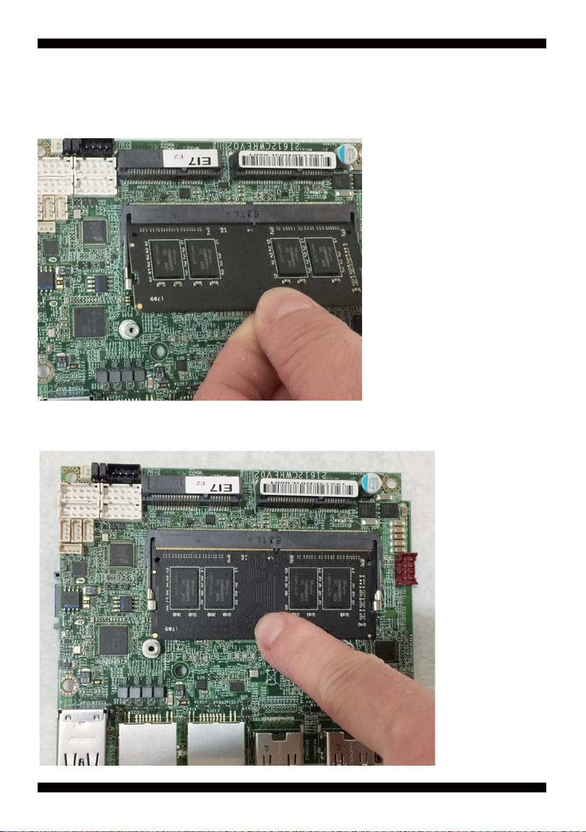
1-3 Installing the SO-DIMM
1. Align the SO-DIMM with the connector at a 45 degree angle.
2. Press the SO-DIMM into the connector until you hear a click.

8
Notices:
1.The connectors are designed to ensure the correct insertion. If you feel resistance,
check t h e connectors & golden fi nger direction, and realign the card.
2. Make sure the retaining clips (on two sides of the slot) lock onto the notches of
the card fi rmly.

9
1-3-1-1 Removing the SO-DIMM
1. Release the SO-DIMM by pulling outward the two retaining clips and
the SO-DIMM pops up slightly.
2. Lift the SO-DIMM out of its connector carefully.

10
1-4 Installing the Mini PCI-e Card (Full Size)
1. Unscrew the screw on the board
3. Gently push down the Mini Card and screw the screw back.
2. Plug in the Mini Card in a 45 angle
11
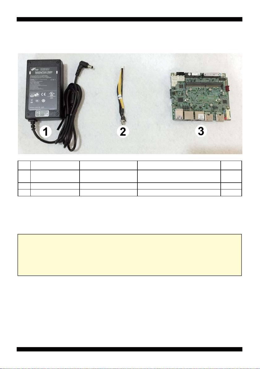
1-5 Packing List
Material Code Description Detail Specifi cation Quantity
16G5212-0623-0100 60W Power
Adapter,12V/5A L Type,2.5Ø,FSP060-DHAN3,FSP 1
26G6003-7350-0100 Power Cable LF, 2.0 2*4/DC JK,L=9cm 1
37G1901-2042001-0 MB-2I612CW-EC0-001 LF,2I612CW-EC0,Rev.:001 1
Optional accessories (items in addition to motherboard)
are not included in the standard packing.
Please contact your dealer to purchase the optional accessories.

12
Chapter-2
This chapter provides the information how to install the hardware of 2I612CW.
Please follow section 1-5, 2-1 and 2-2 to check the delivery package and unpack
carefully. Please follow the jumper setting procedure.
You should follow these
steps to protect the board from the static electric
discharge whenever you handle the board:
1. Ground yourself by a grounded wrist strap at all times when you
handle the 2I612CW.
Well secure the ALLIGATOR clip of the strap to the end of the shielded wire lead from
a grounded object. Please put on and connect the strap before handling the
2I612CW for harmlessly discharge any static electricity
through the strap.
2. Please use anti-static pad to put any components, parts, or tools on the pad whenever
you work on them outside the computer. You may also use the anti-static bag instead of
the pad. Please ask your local supplier for necessary parts on anti-static requirement.
3. Do not plug any connector or set any jumper when the power is on.
Hardware Installation
2-1 Unpacking Precaution
NOTE!
1. Do not touch the board or any other sensitive components without all necessary
anti-static protection.
2. Please pay attention to the voltage limitation of DC-IN 12V 5%.
Overuse of DC-IN voltage limitation or change to another power adapter
(not provided with this system) will VOID warranty.

13
First of all, please follow all necessary steps of section 2-1 to protect 2I612CW
from electricity discharge. With reference to section 1-5
please check the delivery package again with following steps:
1. Unpack the 2I612CW board and keep all
packing material, manual and driver disc etc, do not dispose !
2. Is there any components lose or drops from the board?
DO NOT CONTINUE TO INSTALL THIS BOARD!
CONTACT THE DEALER YOU PURCHASED
THIS BOARD FROM, IMMEDIATELY.
3. Is there any visible damage on the board?
DO NOT CONTINUE TO INSTALL THIS BOARD!CONTACT
THE DEALER YOU PURCHASED THIS BOARD FROM, IMMEDIATELY.
4. Check your optional parts (i.e. DDR, CF etc.), all necessary jumpers
setting to jumper pin-set, and CMOS setup correctly.
Please also refer to all information of jumper settings in this manual.
5. Check your external devices (i.e. Add-On-Card, Driver Type etc.)
for complete add-in or connection and CMOS setup correctly.
Please also refer to all information of connector connection in this manual.
6. Please keep all necessary manual and driver disc in a good condition for future
re-installation if you change your Operating System.
2-2 Unpacking checkup

14
2-3 Dimension-2I612CW

15
2-4 Layout-2I612CW-Connector and Jumper
TOP
CPI1EDP1
JVL1
MPCE1
MPCE2
CPO1
JSB2
JSB1
CBT1
CFP1
CIO1
CC2
CC1
CU7
CU8
CU9
CO1
SODIM1
CU34
CL2
CL1
HDMI2
HDMI1
DP2
DP1
Table of contents


