AZZA KT33-BV User manual

The AZZA KT33-BV Mainboard Page 1
KT33
KT33KT33
KT33-
--
-BV Mainboard
BV MainboardBV Mainboard
BV Mainboard
Manual
ManualManual
Manual
SOCKET A DDR ATX Mainboard
Version 1.x
UM-KT33-BV-E1
Rev 1.0V
Creation Date: 6 March 2002

The AZZA KT33-BV Mainboard
Page 2
Copyright
This publication contains information that is protected by copyright. No part of
it may be reproduced in any form or by any means or used to make any trans-
formation adaptation without prior written permission from the copyright hold-
ers. This publication is provided for informational purposes only. The manufac-
turer makes no representations or warranties with respect to the contents or
use of this manual and specifically disclaims any express or implied warranties
of merchantability or fitness for any particular purpose. The user will assume
the entire risk of the use or the results of the use of this document. The manu-
facturer reserves the right to revise this publication and make changes to its
contents at any time, without prior notice.
2001. All Rights Reserved.
Trademarks
Microsoft®, MS-DOS®, WindowsTM, Windows® 95 and Windows® 98 are reg-
istered trademarks of Microsoft Corporation. AMD® AthlonTMXP, AthlonTM and
DuronTM are registered trademarks of AMD Corporation. Award is the registered
trademark of Award Software, Inc. Other trademarks and registered trade-
marks of products appearing in this publication are the properties of their re-
spective holders.
Package Checklist
This package contains the following items:
•Mainboard
•Users manual
•One IDE cable
•One 34-pin floppy disk drive cable
•One Driver Utility CD
If any of these items are damaged or missing, please contact your dealer or
sales representative for assistance.
Technical Support
If you require additional information or assistance during installation please
contact your dealer. Your dealer will be able to provide the latest information.
User Notice

The AZZA KT33-BV Mainboard Page 3
Chapter 1:- Introduction
Page 5
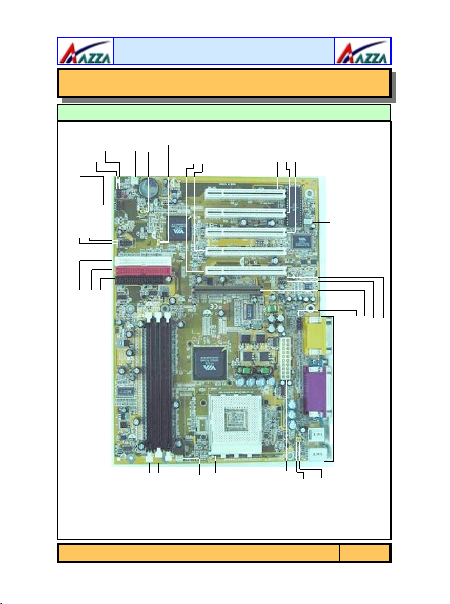
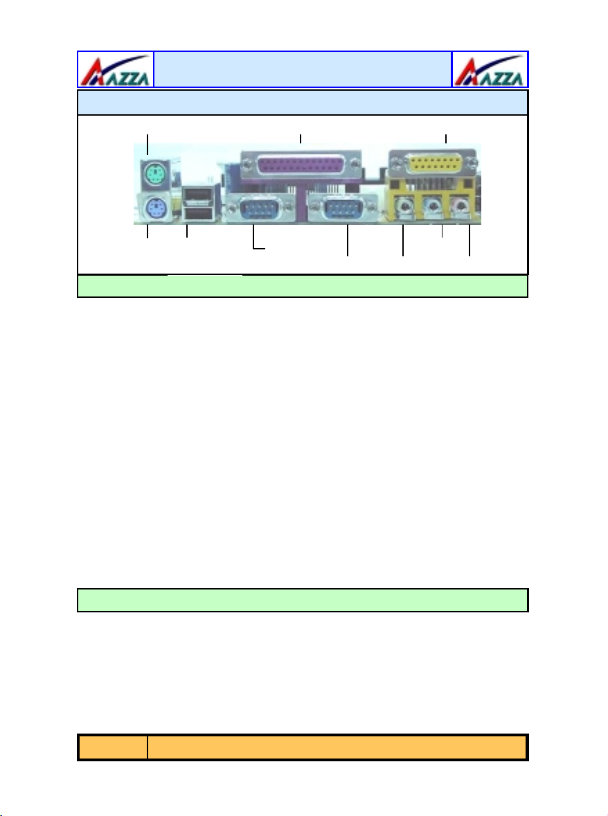
1.1. Mainboard and PC99 External Connector Layout ...................................... 5
1.2. Overview ................................................................................................... 6
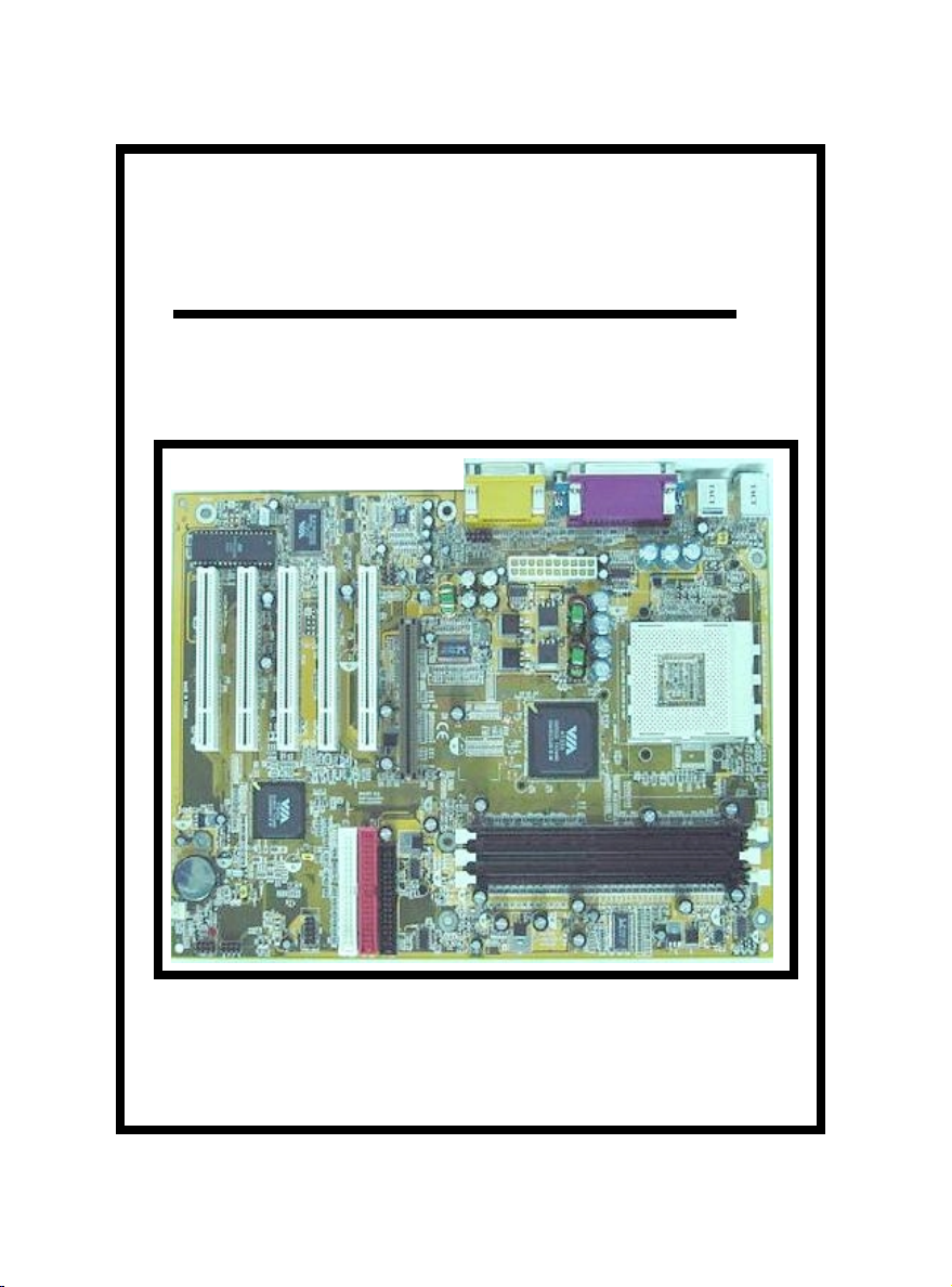
1.2.1. The KT33-BV Mainboard.........................................................................6
1.2.2. Mainboard Dimensions............................................................................6
1.2.3. Environmental Limitations.......................................................................6
1.3. Features and Specifications....................................................................... 6
1.4. System Health Monitor Functions.............................................................. 9
1.4.1. Hardware Monitoring System Utility.........................................................9
1.4.2. Installation.............................................................................................9
1.5. System Intelligence................................................................................... 9
Chapter 2:- Hardware Installation
Page 11
2.1. Installation Checklist................................................................................. 11
2.2. Installation Steps ...................................................................................... 12
2.3. Expansion Slots, Jumpers and Internal Connectors.................................. 13
2.4. CPU, Memory and Expansion Slots ............................................................ 14
2.4.1. Installation of the CPU............................................................................14
2.4.2. Memory Modules....................................................................................14
2.4.3. PCI Slots................................................................................................15
2.4.4. AGP (Accelerated Graphics Port) Slot.......................................................16
2.5. Internal Connectors................................................................................... 16
2.5.1. Floppy Disk Drive (FDC)..........................................................................16
2.5.2. Primary and Secondary IDE Connectors...................................................16
2.5.3. CPU FAN and CHASSIS FAN Connectors...................................................17
2.5.4. ATX Power Supply Connector..................................................................17
2.5.5. WOL (Wake On LAN) Connector .............................................................18
2.5.6. CD Audio In and Auxiliary-In Connectors .................................................18
2.5.7. USB 3 and USB 4 Connectors..................................................................18
2.5.8. Front Audio Connector............................................................................19
2.6. System Panel Buttons and LED Connectors............................................... 19
2.6.1. PW: Power On / Off and External Suspend Switch Connector....................20
2.6.2. SL LED Connector ..................................................................................20
2.6.3. IDE HDD LED Connector.........................................................................20
2.6.4. Reset Button Connector..........................................................................21
2.7. Speaker and Power LED Connector ........................................................... 21
2.7.1. Speaker Connector.................................................................................21
2.7.2. Front Panel Power LED...........................................................................21
Table of Contents

The AZZA KT33-BV Mainboard
Page 4
2.8. External Connectors .................................................................................. 21
2.8.1. PS/2 Keyboard Connector .......................................................................21
2.8.2. PS/2 Mouse Connector............................................................................21
2.8.3. Serial Port 1 (COM 1) and Serial Port 2 (COM 2) Connectors.....................22
2.8.4. Parallel Port Connector ...........................................................................22
2.8.5. USB 1 and USB 2 Port Connectors...........................................................22
2.8.6. Audio/Game Port Connector....................................................................22
2.9. Jumper Settings ........................................................................................ 23
2.9.1. JP1: USB1 and USB2 Power....................................................................23
2.9.2. JP2: Keyboard Power .............................................................................23
2.9.3. JP6: CPU FSB Clock................................................................................24
2.9.4. JP8: Clears CMOS Memory......................................................................24
Chapter 3:- Managing The PC BIOS
Page 25
3.1. Award BIOS CMOS Setup Utility ............................................................. 25
3.2. Main Menu .............................................................................................. 25
3.3. Standard CMOS Setup ............................................................................ 26
3.4. Advanced BIOS Features ........................................................................ 28
3.5. Advanced Chipset Features .................................................................... 31
3.6. Integrated Peripherals ........................................................................... 34
3.7. Power Management Setup ..................................................................... 38
3.8. PNP/PCI Configuration........................................................................... 41
3.9. PC Health Status..................................................................................... 42
3.10. Frequency/Voltage Control .................................................................... 43
3.11. Load Optimized Defaults ........................................................................ 44
3.12. Set Supervisor Password ........................................................................ 45
3.13. Set User Password.................................................................................. 45
3.14. Save & Exit Setup/Exit Without Saving.................................................. 47
Table of Contents

The AZZA KT33-BV Mainboard Page 5
JP6: CPU
CLK
JP8: Clear
CMOS
CN 17:
Chassis Fan
PC 99 ATX Connector
Chapter 1
Chapter 1
Chapter 1 -
-
-Introduction
Introduction
Introduction
Speaker
Power LED
System Panel and
LED Connectors
CN 8: FDD
CN 9: IDE 1
CN 10: IDE 2
DIMM1
DIMM2
DIMM3
CN 13: CPU
FAN
JP1: USB 1, 2
Power
JP2: K/BPower
CN15: ATX
Power Supply
CPU 462 Socket
CN45: AUX-IN
CN21: CD-IN
AGP Slot
CN 39: Front Audio
1.1. Mainboard And PC99 ATX External Connector Layout
CN16: WOL
PCI 2
PCI 1
CN 31: USB4
CN 30: USB 3
PCI 3
PCI 4
PCI 5
Introduction

The AZZA KT33-BV Mainboard
Page 6
1.2.1. The KT33-BV Mainboard
The KT33-BV mainboards are AMD®Socket A platforms which can support
Athlon™XP, Athlon™or Duron™CPU’s. They come with three onboard DDR
DIMM slots that are able to support a maximum memory of 3GB. They also
come with 5 PCI slots and 1 AGP (Accelerated Graphics Port) slot. They all
come with Onboard Audio (AC’97 2 channel) . Each KT33-BV mainboard
comes with 4 (Ver 1.1) USB connectors and two serial ports. They also have a
WOL (Wake-On LAN) Connector, 2 fan connectors a CD-IN connector and an
AUX-IN connector.
1.2.2. Mainboard Dimensions
These boards are ATX form factors. Their dimensions are:
Width 305 mm
Length 220 mm
1.2.3. Environmental Limitations
Operating Temperature: 10°C to 40°C (50°F to 104°F)
Required Airflow: 50 linear feet per minute across the CPU
Storage Temperature: -40°C to 70°C (-40°F to 158°F)
Humidity: 0 to 90% non-condensing
Altitude: 0 to 10 000 feet
1.2. Overview
Processor
The KT33-BV mainboards support Socket A AMD® Athlon™XP,Athlon™,
and Duron™ CPUs.
1.3. Features and Specifications
LINE-IN MIC-IN
CN18: MIDI/GAME
CN1: PS/2 KB
CN2: PS/2 MS
CN3: COM 1
CN4: COM 2
CN5: LPT
SPK-OUT
CN7: USB2
CN6: USB1
PC 99 ATX External Connector
Introduction

The AZZA KT33-BV Mainboard Page 7
CPU Switching Voltage regulator
This mainboard is equipped with a switching voltage regulator that automati-
cally detects a DC power supply from +1.10V to +1.85V.
System Memory
The KT33-BV mainboards use Double Data Rate Dual Inline Memory Modules
(DDR DIMM). Each mainboard has three 184-pin DIMM sockets which are able
to support 2.5V (power level) single-sided or double sided PC1600 (DDR200),
PC2100 (DDR266) or PC2700 (DDR333) DDR DIMM modules.
Expansion Slots
These mainboards are equipped with five dedicated PCI slots and one AGP
slot.
Onboard Audio Features
Supports Microsoft DirectSound/ DirectSound 3D and AC97 Full Duplex.
Word Size
•Data Path: 8-bit, 16-bit, 32-bit, 64-bit
•Address Path: 32-bit
Front Side Bus Frequency (FSB)
The KT33-BV mainboards are able to support a Front Side Bus Frequency
(FSB) of 200MHz or 266MHz.
BIOS
•Award BIOS, Windows 95/98 Plug and Play (PnP) compatible.
•Supports SCSI sequential boot-up.
•Flash EPROM for easy BIOS upgrades.
•Supports DMI 2.0 function
Desktop Management Interface (DMI)
The mainboard comes with DMI 2.0 built into the BIOS. The DMI utility in the
BIOS will automatically record different information about your system
configuration and store this information in the DMI pool, which is a part of the
system board's Plug and Play BIOS. DMI, along with the appropriately
networked software, is designed for easy inventory, maintenance and the
simplified troubleshooting of computer systems.
Northbridge Southbridge I/O Chipset
VIA KT333 VIA VT8233A Winbond W83697HF
Chipsets
Introduction

The AZZA KT33-BV Mainboard
Page 8
WOL (Wake-On-LAN) Port
One WOL connector supports Wake-On-LAN functionality.
USB Ports
USB allows data exchange between your computer and a wide range of
simultaneously accessible external Plug and Play peripherals. These models
are equipped with four (version 1.1) USB connectors. USB 1 and USB 2 are
external connectors. They can be found on the PC 99 ATX connector. The other
USB connectors are internal connectors and can be used to connect other USB
devices. (Cables for the internal connectors are sold separately).
Connectors
•Two IDE connectors.
•One floppy drive interface supports up to two 2.88MB floppy drives.
•One 20-pin ATX power supply connector.
•Two fan connectors.
•One CD audio-IN connector.
•One Aux-IN connector
•One WOL (Wake-On-Lan Connector)
•One Front Audio Connector
ATX Double Deck Ports (PC 99 color-coded connectors)
•Two USB ports.
•Two external DB-9 serial port connectors: COM 1(UART) and COM 2
(UART).
•One SPP/ECP/EPP DB-25 parallel port.
•One mini-DIN-6 PS/2 mouse port.
•One mini-DIN-6 PS/2 keyboard port.
•One game/MIDI port.
•Three audio jacks: speak-out, line-in and mic-in.
PCI Bus Master IDE Controller
•Two PCI IDE interfaces support up to four IDE devices.
•KT33-BV mainboards support ATA/33, ATA/66, ATA/100 and
ATA/133 hard drives.
•PIO Mode 3 and Mode 4 Enhanced IDE (data transfer rate up to
16.6MB/sec.).
•Bus mastering reduces CPU utilization during disk transfer.
•Supports ATAPI CD-ROM, LS-120 and ZIP.
Introduction

The AZZA KT33-BV Mainboard Page 9
1.4.1. Hardware Monitoring System Utility
The mainboards both come with the Hardware Monitoring System utility
contained on the CD. It is capable of monitoring the system’s hardware
conditions such as the temperature of the processor, voltage, and the speed of
both the CPU and chassis fans. You are allowed to manually set a range to the
items being monitored. If the values are over or under the set range a warning
message will automatically pop up. We recommend that you use the Default
Settings, which are the ideal settings that will maintain the system in a good
working condition.
1.4.2. Installation
To install this utility, please insert the CD into the CD-ROM drive. The auto run
screen (Driver Utility) will automatically appear. Click the Hardware Monitoring
button, choose the chipset, model number and the OS that is installed. Please
refer to the CD “Readme” file for further installation instructions.
The mainboard is capable of monitoring the following health conditions of your
system:
1. Processor temperature. It has an overheat alarm.
2. VCORE/3.3V/5V/12V/-12V voltages and failure alarm.
3. Processor and chassis fan speeds. It has a failure alarm for these fans.
4. Read back capability that displays temperature, voltage and fan speed.
1.4. System Health Monitor Functions
Note: Only use this utility in Windows ® 95 or Windows ® 98 operating systems.
Dual Function Power Button
Depending on the setting in the Soft-Off By Power-Button field of the Power
Management Setup, this switch allows the system to enter the Soft-Off or
Suspend mode.
RTC Timer to Power-on the System
The RTC installed on the system board allows your system to automatically
power-on at a set date and time.
Wake-On-LAN Ready
The Wake-On-LAN function allows the network to remotely wake up a Soft
Power Down (Soft-Off) PC. Your LAN card must support the remote wakeup
function. The 5V SB power source of your power supply must be at least
720mA.
ACPI Ready
The mainboard is designed to meet the ACPI (Advanced Configuration and
Power Interface) specification. ACPI has energy saving features that support
OS Direct Power Management (OSPM) for round the clock PC operation.
Introduction
1.5. System Intelligence

The AZZA KT33-BV Mainboard
Page 10
CPU Thermal Protection
This function is only for AMD Athlon XP and Duron (Morgan) processors.
1. If you haven’t installed a heat-sink with cooling FAN, or if you have installed
it incorrectly, this function will prevent the system from being turned on. If
you are unable to turn on the system check to see if the heat-sink with
cooling FAN has been installed correctly.
2. If the cooling FAN stops functioning the heat of the CPU will increase and
the system will auto power-off to protect the CPU against overheating.
Introduction

The AZZA KT33-BV Mainboard Page 11
The following is a checklist of all the expansion slots, jumpers and connectors
that should be configured on your mainboard before you can run your pc.
Chapter 2
Chapter 2
Chapter 2 -
-
-Hardware Installation
Hardware Installation
2.1. Installation Checklist
Installation Checklist
Expansion Slots and Sockets
CPU Socket
DIMM Slots
PCI Slots
AGP Slot
Socket A AMD® Athlon™XP, Athlon™ and Duron™ CPU’s.
Three 184 pin slots that support up to 3GB of DDR200/
DDR266/DDR333 SDRAM
Five 32 bit PCI Slots.
One (2x/4x) AGP slot
Internal Connectors
CN8
CN9
CN10
CN13
CN15
CN16
CN17
CN21
CN30
CN31
CN39
CN45
Floppy Disk Drive
Primary IDE
Secondary IDE
CPU Fan
ATX Power Supply
Wake On Lan
Chassis Fan
CD Audio In
Universal Serial Bus 3
Universal Serial Bus 4
Front Audio
Auxiliary In
FDC
IDE1
IDE2
CPU Fan
ATX
WOL
FAN2
CD-In
USB3
USB4
Front Audio Connector
Aux-IN
CN1
CN2
CN3
CN4
CN5
CN6
CN7
CN18
PS/2 Keyboard Connector
PS/2 Mouse Connector
Serial Port 1
Serial Port 2
Parallel Port
Universal Serial Port 1
Universal Serial Port 2
Game/Audio Port
PS/2 KB
PS/2 MS
COM1
COM2
LPT
USB1
USB2
Audio/Game
External Connectors
Hardware Installation

The AZZA KT33-BV Mainboard
Page 12
You need to complete the following installation steps before you can use your
PC. •Check and Set the Mainboard Settings.
•Install the Central Processing Unit (CPU).
•Install the Memory Modules.
•Install the Expansion Cards.
•Connect the Ribbon Cables, Panel Wires and the Power Supply.
•Setup the system BIOS
Before you start installing your mainboard we strongly recommend
that you use a grounded anti-static mat. We further recommend
that you attach an anti-static wristband, which is grounded at the
same location as the mat, to your wrist.
2.2. Installation Steps
Installation Checklist (Continued)
Speaker and Power LED Connector
PW
SL
HL
RS
Power On/Off and Suspend Switch Connector.
Standby LED Connector
HDD LED Connector
Reset Button Connector
Speaker and Power LED Connector
PWR-LED
SPK Power LED
Speaker Connector
Jumpers and Switches
JP1
JP2
JP6
JP8
USB 1,2 PWR
KB Power
CPU CLK
Clear CMOS
Hardware Installation

The AZZA KT33-BV Mainboard Page 13
2.3. Expansion Slots, Jumpers and Internal Connectors
CN17: Chassis Fan
PW SL HL RS
1111
1 PWRLED
1 SPKR
1 1 1
1
CN31:
USB4
CN30:
USB3
CN 10:
IDE2
CN 9:
IDE1
CN 8:
FDD
JP8: Clear CMOS
1
DIMM 1
DIMM 2
DIMM 3
CN 15: ATX
Power Supply
1
1
AGP Slot
JP2: K/B PWR
JP1: USB1,2 PWR
1
1
PCI 1PCI 2PCI 3PCI 4PCI 5
CN16: WOL 1
CN13: CPU Fan
1
1
CN21: CD-IN
CN45: AUX-IN
JP6: CPU Clk
1
1
CN39: Front
Audio
CN17: Chassis Fan
PW SL HL RS
1111
1 PWRLED
1 SPKR
1 1 1
1
CN31:
USB4
CN30:
USB3
CN 10:
IDE2
CN 9:
IDE1
CN 8:
FDD
JP8: Clear CMOS
1
DIMM 1
DIMM 2
DIMM 3
CN 15: ATX
Power Supply
1
1
AGP Slot
JP2: K/B PWR
JP1: USB1,2 PWR
1
1
PCI 1PCI 1PCI 2PCI 2PCI 3PCI 3PCI 4PCI 4PCI 5PCI 5
CN16: WOL 1
CN16: WOL 1
CN13: CPU Fan
1
1
CN21: CD-IN
CN45: AUX-IN
CN21: CD-IN
CN45: AUX-IN
JP6: CPU Clk
1
1
CN39: Front
Audio
Hardware Installation

The AZZA KT33-BV Mainboard
Page 14
2.4.2. Memory Modules
The KT33-BV mainboards have three 184-pin DDR DIMM slots and are able to
support a maximum of 3GB of DDR200/266/333 memory. The DDR DIMM
slots are located on the right hand side of the board. To install the DIMM’s into
these slots, make sure the white lever at each side of the slot has been pulled
down to an angle of approximately 45°. Make sure that the DIMM is in the
correct orientation. Place the DIMM on the slot and push down firmly.The white
levers will come back up and lock the module in place.
Important: The DIMM’s can only be fitted into the slots in one orien-
tation. Make sure that the DIMM’s are in the correct orientation and
the pins are correctly aligned before you insert them.
2.4.1. Installation of the CPU
To install your processor, please complete the following set of instructions
1. Locate a small dot marked on the top of the CPU. This mark indicates
Pin 1 of the CPU.
2. Locate Pin 1 for the Socket on the mainboard.
3. There is a lever on the side of the socket. First push this lever side-
ways and then lift it to a 90-degree angle.
4. Insert the CPU into the Socket. Please make sure that Pin 1 for the
CPU is inserted into Pin 1 of the Socket.
5. When the CPU is installed correctly push the lever back into place.
6. Install a proper heat sink with cooling fan for proper heat dissi-
pation. Failing to install a heat sink with cooling fan may cause over-
heating which will burnout your CPU and damage your mainboard.
IMPORTANT: CPU COOLING FAN
Please ensure that you have an approved heat sink with cooling fan.
Without a proper heat sink with cooling fan you will damage both the
mainboard and the CPU.
2.4. CPU, Memory and Expansion Slots
CPU Socket 462
SOCKET462
Lock Free SOCKET462
Lock Free
Supports AMD Socket A
Pin 1
Athlon XP
Athlon
Duron
Hardware Installation

The AZZA KT33-BV Mainboard Page 15
DIMM1
DIMM2
DIMM3
2.4.3. PCI Slots
The KT33-BV mainboards each
come with five PCI slots. They
are located on the left hand side
of the board. Both PCI and PCI
expansion cards may require
IRQ’s. This mainboard complies
with Plug and Play (PnP) specifi-
cations. Whenever a PnP compli-
ant card is added the system
will automatically be configured
and the IRQ’s will be assigned
automatically.
When you are inserting your PCI
card make sure that the pins are
correctly aligned. When the pins
are properly aligned with the
hole’s in the slot, push down
gently. 5 4 3 2 1
49 Pins
11 Pins
PCI Slots
NOTE: “Out Of Memory” Error Message
If you have installed more than 512 MB of RAM and are running Microsoft Windows Mil-
lennium Edition, Windows 98 Second Edition, Windows 98 or Windows 95 you may ex-
perience memory problems. Two symptoms of these problems are being unable to run
an MS-DOS session while you are running Windows or the computer may stop respond-
ing while Windows is starting.
There are three possible solutions to this problem:
1) Reduce the amount of memory Vcache uses to 512 MB or less by altering the Max-
FileCache setting in the System.ini file.
2) Use the System Configuration Utility to reduce the amount of memory Windows
uses to 512 MB or less.
3) Reduce the memory installed on your computer to 512 MB or less.
This problem can also occur if an Advanced Graphic Port (AGP) video adapter is used.
184-pin DIMM Slot
40 pins 52 pins
Hardware Installation

The AZZA KT33-BV Mainboard
Page 16
2.5.1. Floppy Disk Connector
(FDC)
Connector: CN 8
Type: 34 pin block
The FDC connector can support two
Floppy drives. It is located at the
front of the mainboard. To connect,
use the ribbon-cable that has been
provided. Make sure that the red
strip is connected to PIN 1 of the
connector.
2.5.2. Primary and Secondary
IDE connectors
Connector:
CN 9 (primary)/ CN 10 (secondary)
Type: 40 pin blocks
The KT33-BV mainboards have two
IDE connectors: a primary and sec-
ondary. Each IDE connector can sup-
port two IDE drives. These main-
boards can therefore support up to
four IDE devices each. If you install
two hard drives, you need to config-
ure the second drive to slave mode
in the BIOS setup. Please refer to
your hard drive manual for the ap-
propriate jumper settings.
IDE Connectors
Pin 1
IDE 1
Pin 1
IDE 2
Floppy Disk Connector (FDC)
Pin 1
66 pins
2.4.4. AGP (Accelerated Graphics
Port) Slot
AGP is a dedicated bus slot. It operates
at 66 MHz and transfers data at a rate
up to 1066 MB/s. This allows 3D appli-
cations to run more smoothly. The
KT33-BV mainboards each come with
one AGP slot. These slots are able to
support 2x and 4x AGP cards.
AGP Slot
2.5. Internal Connectors
Hardware Installation

The AZZA KT33-BV Mainboard Page 17
2.5.4. ATX Power Supply Connector
Connector: CN 15
Type: 20 pin block
This must be connected to an ATX power supply. The plug from the power sup-
ply can only be inserted in one orientation. Make sure the pins are correctly
aligned. Find the correct orientation and push the plug down firmly.
2.5.3. CPU Fan and Chassis Fan Connectors
Connector: CN13 (CPU Fan)/CN17 (Chassis Fan)
Type: 3 pin
The cooling fans must be connected to their respective power connectors. If
you have installed the hardware-monitoring feature you will be able to monitor
the rotating speed of the CPU cooling fan in your Windows operating system.
Ground
Fan Signal
+12V DC
1
2
3
CPU and Chassis Fan Connectors
CPU Fan
Chassis Fan
Ground
Fan Signal
+12V DC
1
2
3
ATX Power Supply Connector
Pin 1 Pin 11
+12V
5VSB
PWR_OK
GND
+5VDC
GND
+5VDC
GND
+3.3VDC
+3.3VDC
+5VDC
+5VDC
-5VDC
GND
GND
GND
PS_ON#
GND
-12VDC
+3.3VDC
Hardware Installation

The AZZA KT33-BV Mainboard
Page 18
2.5.7. USB 3 and USB 4 connectors
Connector: CN 30 /CN 31
Type: 10 pin
You already have two USB ports available, USB 1 and 2 (see external connec-
tors). The internal USB connectors allow you to add on an optional kit to ex-
pand the total number of USB ports available. The KT33-BV mainboards has
two internal USB connectors (CN30 and CN31). This enables you to use an
extra two USB devices. Cable for these additional connectors needs to be pur-
chased separately.
2.5.6. CD-IN/AUX-IN Connector
Connector: CN 21 (CD-IN/ CN 45 (AUX-IN)
Type: 4 pin un-housed
The KT33-BV mainboards have one CD-IN connector and one AUX-IN connec-
tor . The CD-IN connector is used to connect the CD ROM audio out and al-
lows the system to receive audio input from the CD ROM. The AUX-IN con-
nector allows the system to receive signals from other audio devices like a ra-
dio or tape.
CD Audio In and Auxiliary In
Left Channel AUX-IN
Ground
Ground
Right Channel AUX-IN
1
2
3
4
1 Left Channel Audio In
2 Ground
3 Ground
4 Right Channel Audio In
2.5.5. WOL Connector
Connector: CN 16 (WOL)
Type: 3 pin
The Wake-On-LAN (WOL) connector
must be connected to a LAN card that
has Wake-On-LAN output. This con-
nector powers up the system when a
wakeup packet or signal is received
through the LAN card.
WOL Connector
1 5V_SB
2 Ground
3 WOL
Hardware Installation

The AZZA KT33-BV Mainboard Page 19
2.6. System Panel Buttons and LED Connectors
Pin 1 Pin 2
PW Power On/OFF and Suspend Switch
Connector +5V DC Pull Up Ground
SL Standby LED Connector Standby DC Pull
UP Ground
HL HDD LED Connector +5V DC Pull Up Ground
RS Reset Button Connector Reset Control Ground
Buttons and Connectors
2.5.8. Front Audio Connector
Connector: CN 39
Type: 10 pin
The front audio connector is an innovative development. This connector is designed to be
used with a Front-Utility Panel. The utility panel was developed so that a user is able to
bring the speaker out, microphone in connectors to the front of their PC. This makes
things like plugging in speakers and earphones much less troublesome. See the diagram
on the following page.
Pin Pin
1 MIC-IN 2 Ground
3 MIC-IN Pull
Up 4 NC
5 LINE-OUT R 6 NC
7 NC 8 Key
9 LINE-OUT L 10 NC
Front Audio Connector
10
9
8
7
6
5
4
3
2
1
Connectors for USB3 and USB4
9 Key
7 Ground
5 Data+
3 Data-
1 VCC 2 VCC
4 Data-
6 Data+
8 Ground
10NC
USB3USB4
Hardware Installation
Table of contents
Other AZZA Motherboard manuals