Termomont Temy Plus P 20 User manual

Temy Plus P 20
Residential cooker for solid fuels according EN 12815
Technical User Manual
Customer service:
Termomont d.o.o. Prhovačka bb 22310 Šimanovci
tel. 022 480404, 022 480494 fax 022 480494 www.termomont.rs
April 21, 2016

Contents
1 Technical data 2
1.1 Boiler properties TEMY PLUS P 20 ............................. 4
1.2 Boiler parts TEMY PLUS P 20 ............................... 5
1.3 OnProduct............................................ 6
1.4 Primary, secondary and tertiary air . . . . . . . . . . . . . . . . . . . . . . . . . . . . . . . 7
2 Directions for storage and transport 8
2.1 Deliveryform........................................... 8
2.2 Deliveryrange........................................... 8
3 Introductory remarks 9
4 Safety remarks 9
5 Connecting the boiler to the central heating system 9
5.1 Filling the system with water . . . . . . . . . . . . . . . . . . . . . . . . . . . . . . . . . . 9
5.2 Connecting the boiler with a closed central heating system . . . . . . . . . . . . . . . . . . 10
5.2.1 Installationmethod1 .................................. 10
5.2.2 Installationmethod2 .................................. 11
5.3 Use of temperature relief valve with obligatory filling . . . . . . . . . . . . . . . . . . . . . 12
5.4 Fitting the boiler to an open central heating system. . . . . . . . . . . . . . . . . . . . . . 12
6 Boiler operation 13
7 Chimney 14
8 Modes of Operation 15
8.1 Predominantly Heating or Baking Mode . . . . . . . . . . . . . . . . . . . . . . . . . . . . 15
8.2 WinterorSummerMode..................................... 15
9 Overheat protection using the thermostatic valve (closed system) 16
10 Boiler cleaning and maintenance 17
1

1 Technical data
2

3

1.1 Boiler properties TEMY PLUS P 20
Overall nominal power 20 KW
Power transfered to the heating system 15 KW
Overall width 1160 mm
Overal height 890 mm
Overall length 705 mm
Necessary draught 14 Pa
Flow 1"
Return 1"
Weight 310 kg
Flue opening 148 mm
Water content 22 lit
Chamber volume 36 dm3
Max working pressure 3 bar
Dimensions of the oven 350x230x405 mm
Flue gas temperature 212˚C
Efficiency 80,56 %
CO Emissions (13 % O2) 0,0929 %
TOC (OGC) 17,64 mg/m3
Dust 27,91 mg/m3
4
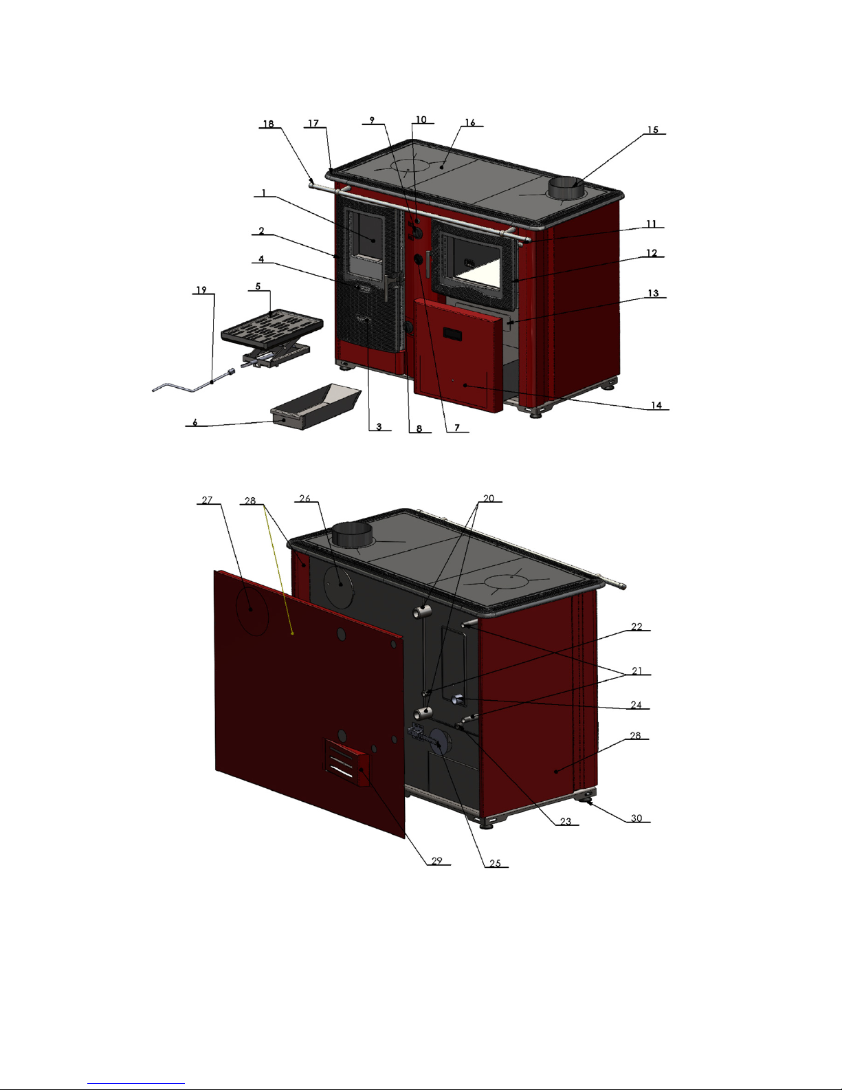
1.2 Boiler parts TEMY PLUS P 20
Boiler part description: 1 Combustion chamber 2 Iron cast door 3 primary air 4 Sekundarni vazduh stakla 5
Iron cast grid 6 Ashtray 7 thermomanometar 8 secondary air control 9 Handle of flap for gas flue (water/oven)
10 handle of flap for gas flue second. (water/oven) 11 handle of chimney flap 12 oven door with thermostat
13 Cover for cleaning stove 14 Box for wood 15 Chimney (upper) 16 cooking plate 17 Decorative iron cast 18
Decorativ rod 19 Rod for fire place grid 20 flow / return 21 Changer 22 Probe 23 Filling / Emptying 24 Tercial
air 25 Thermoregulator 26 open for chimney on back side of boiler 27 Open for chimney on back housing plate
28 Housing plate 29 Cover of thermoregulator flap 30 Pedestal with adjustable legs
5

1.3 On Product
TEMY PLUS P is a steel hot-water stove-boiler for central heating with cooking or baking in the same
time, produced according to EN 12815. It is very easy to use and maintain.
Boiler chamber is entirely made of steel (welded steel-plates), while the doors and the frame of the
cooking plate is made of cast iron. Heating chamber is made of 5mm thick steel plates.
The upper door and the oven door are cast-iron made and have a window made of fireproof glass.
The flue opening is placed both on the upper side and on the back side of the boiler, so the customer
can chose which one to use and which one to close:
The oven are made of stainless steel AISI 314 for maximum hygienic conditions for food preparation.
6

1.4 Primary, secondary and tertiary air
TEMY PLUS P has three air adjustment settings to make sure combustion process is perfect. Primary
air is controled by the embedded automatic thermo-regulator mounted on the back side of the boiler:
The setting of the primary air is located on the front side of the boiler.
Secondary air is adjusted at the main combustion chamber door:
Finally, tertiary air holes are located ath the back wall of the heating chamber (cannot be adjusted).
Exit flue gas flap control: On the right-hand side beside the oven there is another flap handle located.
Moving this handle back and forth, it is possible to control the flue gas opening area and also to adjust
the whether air is going straight out to the flue above the oven or circulating around the oven.
7
2 Directions for storage and transport
2.1 Delivery form
Boiler is shipped with plastic protection sleeve on a europallet.
Boiler must be in its upright position all the time.
The rotation of the boiler during the shipment or installation represents a serious risk and
can lead to damaging the boiler.
It is forbidden to place one boiler onto another.
The boiler can be stored only in closed rooms with no atmospheric influence. The humidity
in the storing room also must not exceed the critical value of 80%, so as not to create any condensate.
The temperature of the storing room must be in the range from 0 ˚C to 40 ˚C.
When unpacking the boiler, you must check whether the paint on the boiler coating has been
scratched somewhere and whether all parts of the boiler stand in their proper position.
2.2 Delivery range
Together with the boiler, also the following parts are supplied:
•Cleaning kit with an external ash tray
•Warranty paper and this boiler manual
Along the boiler following parts are NOT INCLUDED:
•Thermo-manometer and the safety group
•Mixing valve
•Boiler valves etc.
8

3 Introductory remarks
The end user must follow the guidelines from this manual all the time. In contrary case the
warranty won’t be acknowlidged.
Pay strict attention that boiler valves are always open while boiler in use.
Don’t forget to do a mechanical reset of the circulation pump at start of every heating season.
Clean the boiler on a regular base.
4 Safety remarks
While in use, some parts of the boiler may be hot. Don’t touch the boiler without appropriate
hand protection against heat.
If some parts of the boiler occur to be damaged it is strictly forbidden to continue using the
boiler.
Use of the temperature relief valve is OBLIGATORY with this boiler to ensure safety in
heating systems using solid fuels.
5 Connecting the boiler to the central heating system
An expert should be entrusted with the mounting of the heating and the initial operation. This
must be a person who will take over the responsibility and guarantee the correct operation of the boiler
and of the complete central heating system. In the case of an incorrectly planned system with manifesting
deficiencies caused by the respective person’s incorrect installation of the system, which can again lead
to an incorrect operation of the boiler, the complete liability for the material damage and potential new
costs arising in relation to it is borne exclusively by the person who was entrusted with the mounting of
the central heating system, and not by the boiler manufacturer, sales representative or seller.
5.1 Filling the system with water
Filling the system with water is to be done using the tap valve connection of the boiler.
When filling the system with water take care that no air remains in the boiler.
The filling process is done when no air is coming out through automatic air vent and pressure gauge is
showing the value between 1,5 and 2,5 bar (closed systems). Air vent is to be set at the highest point of
the (closed) central heating system. If the pressure is below 1,5 bar the filling process must be repeated.
9

For open systems, working pressure depends on the overall height of the system and the open expansion
vessel (1 bar for each 10 m is an estimate).
After the filling process is done, it is obligatory to close the drain tap valve, close the water supply to
the water-filling pipe and detach the water-filling pipe.
5.2 Connecting the boiler with a closed central heating system
The use of a safety valve is obligatory (with a 2-3 bar threshold, depending on the power of the
boiler) and it must be mounted near the boiler.
It is essential to have a thermometer and a manometer installed to the system.
It is also recommended to mount a filth catcher on the return line.
Depending on the position of the boiler in relation to the pipe-work and the radiators – the installation
can be carried out using one of two methods.
5.2.1 Installation method 1
If the boiler is positioned on the same level or higher than the pipe-work and radiators.
Each of the following items of equipment shall be fitted along the flow line:
1. Automatic air vent.
2. Safety valve (spring valve is recommended).
3. Expansion vessel.
4. Boiler valve.
The safety pressure valve must always be positioned and mounted close to the boiler. It
must be easily identifiable and allow for easy access. The safety pressure valve must be set to a nominal
pressure of 2.5 bar. The valve must open and operate smoothly at 2.5 bar. Diameter for the aperture
at the seat of the valve must be at least 15mm. Connecting pipework to the boiler must be as short
as possible. Welds, joints or any possible blockage to this pipe-work must be prevented. Bends in the
pipe-work should be avoided if possible. Unavoidable bends should be of a diameter r>3D (D = radius
of curvature) and less than α> 90 ˚C .
The closed expansion vessel shall be fitted close to the boiler. Connecting pipework should
be as short as possible. Fit the expansion vessel in horizontal alignment to the pipe to ensure equal
distribution of pressure. The volume of the expansion vessel is determined by the output/capacity of the
boiler. A ratio of 1 kW:1 litre should be used. The safety pressure valve and the expansion vessel should
be fitted in close proximity to each other, in the following order: expansion vessel closest to the boiler,
followed by the safety pressure valve.
In the event of power failure and the boiler fails to operate correctly – any sudden increase of
pressure will be controlled first by the expansion vessel, on any further increase in pressure the safety
pressure valve will open.
10

5.2.2 Installation method 2
To be used in the case of the boiler being positioned and installed at a lower level than the installed
pipework and radiators.
As shown on Figure, following elements are connected along the FLOW:
1. Automatic air vent
2. Safety valve
3. Circulation pump (separated with ball valves on each side so that it can be easily replaced if
necessary).
Expansion vessel is on the RETURN line in this case.
Expansion vessel and safety valve are connected following the rules described in the previous
chapters. For safe operation info on additional equipment such as expansion vessel and safety valve please
refer to manuals delivered with those products.
11
5.3 Use of temperature relief valve with obligatory filling
The temperature relief valve (shown below) must be present in the system. The valve must
be installed by a qualified technician in accordance with the instructions given in the manual from the
producer of the valve.
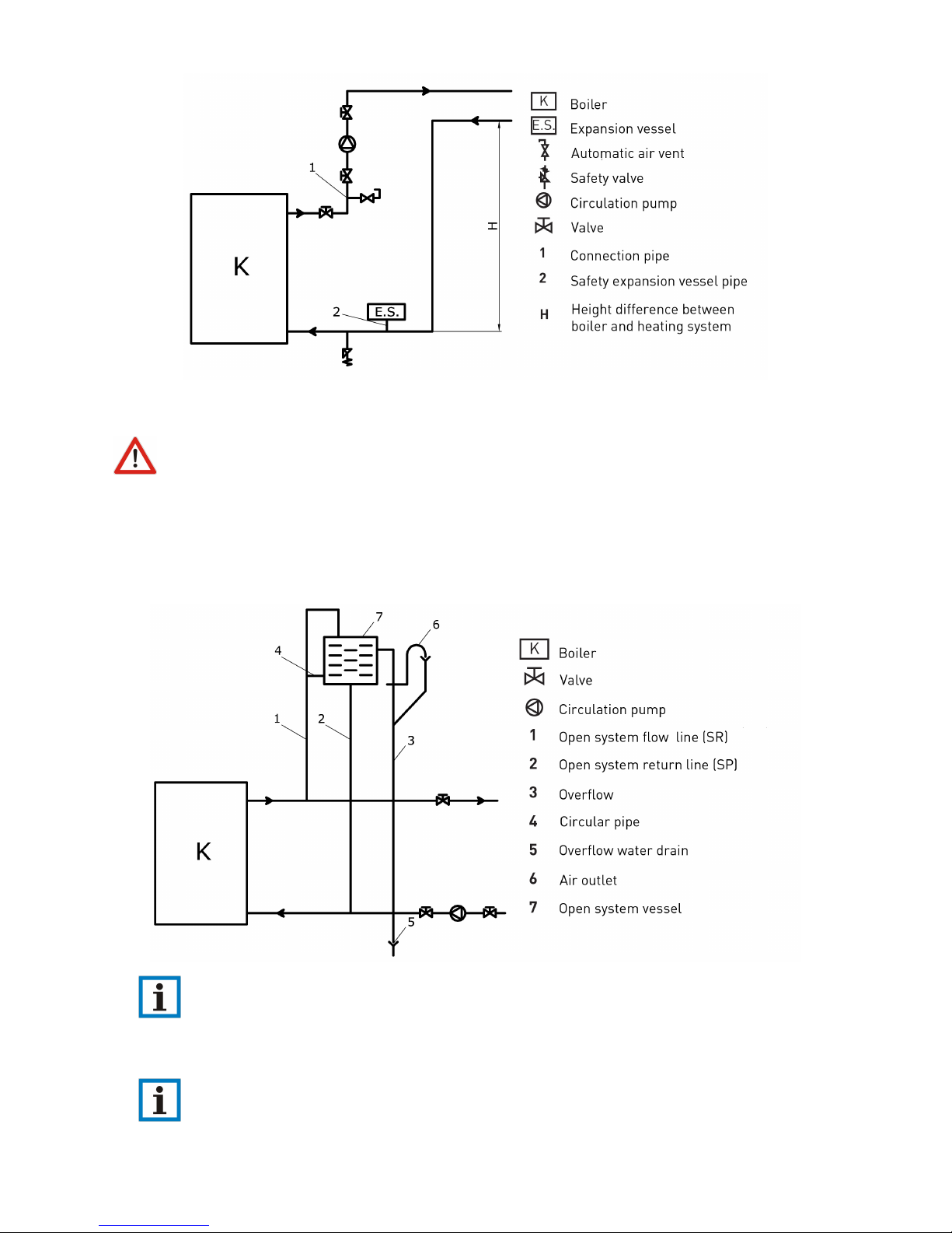
5.4 Fitting the boiler to an open central heating system.
The connecting scheme of an open central heating system is depicted on the figure.
When using open system on the FLOW line following elements are to be installed: safety
pipework for the open expansion vessel, boiler valve. On the RETURN line come safety return line of
the open expansion vessel, boiler valve and circulation pump valves.
Open expansion vessel is connected to the hot-water distribution pipes (FLOW and RETURN)
as shown on Figure – with an additional OVERFLOW pipe output plus CIRCULATION pipe (to prevent
12

freeze during winter months).
Please note that no additional items shall be connected to the open expansion vessel – espe-
cially not valves.
The size of expansion vessel is deducted from the following equation:
V= 0,07Vwater (l)
Vwater (l)is the water volume in the entire installation. Diameter for the pipework of the expansion vessle
line should be round 25 mm.
Open expansion vessel is to be positioned vertically above the highest heating element.
6 Boiler operation
First putting into operation is performed exclusively by a skilled person. Before putting in operation
please make sure that:
•boiler is connected on central heating installation properly
•there is no air in the central heating installation and pressure is within range
•proper working cycle for circulation pump is chosen.
Heating by solid fuel (manual operation) can be performed in two ways:
1. Heating from above – put coal (or wood) over the fireplace pipes (“grid”) (no ash should be present).
The draught regulator is at the maximum position. Using a tiny piece of wood or coal, light a fire on
the top. When the fire begins to burn, draught regulator is set on desired temperature / position.
2. Heating from below – put small amount of solid fuel over the fireplace pipes (“grid”) (no ash should
be present) and set up a fire. The draught regulator is at the maximum position. When the
fire begins to burn, add larger amount of fuel and set draught regulator on desired temperature /
position.
Make sure that lower boiler doors are closed during boiler use.
In case of an uncontrolled increase of pressure and temperature of the water in the boiler, due
to various reasons (such as power failure causing interruption of the circulation pump operation, circu-
lation pump defect, uncontrolled entry of air into system) close all air supply to the boiler or eventually
take the fire out if the safety conditions allow that (there are no inflammable materials in the area). In
case of power failure put the draught regulator in the zero position and the flap on the boiler chimney
take-up in the closed position.
It is obligatory to pay special attention that the pressure inside the installation is within
range (> 1,5 bar for closed systems). If the pressure is below the critical value, stop the boiler operation
and refill the system when the boiler is cold.
13

The water hardness may not exceed the recommended value. If you heat the boiler using
coal, depending on the kind of coal and quality of combustion, boiler is to be cleaned at least every 30
days. Dirtier the boiler, the efficiency of the system is smaller.
It is not allowed to extinguish the fire in the boiler artificially, it is forbidden to sprinkle the
water inside the heating chamber. After the heating season boiler should cleaned from ash and soot and
the chamber should be treated with some protection agent against corrosion.
In case of any mechanical problem (the draught regulator is blocked, or the circulation pump is
defect) stop the boiler operation first – only when the boiler is cold, reparation action can be undertaken.
7 Chimney
The purpose of the chimney is to take out the products of combustion but also to secure necessary air
draught in the boiler.
The purpose of this chapter is only to provide basic information. Please consult your chimney
supplier for details. We take no responsibilty if the chimney is not chosen properly.
The graph below gives an idea how to chose the necessary height for the chimney as a function of
chimney opening. For instance, if we have a 160 mm diameter of the chimney, minimum chimney height
would be 6m for 20 KW model or 8m for 25 KW model. For 180 mm diameter chimney should be at
least 5m high for a 20 KW boiler (6m for 25 KW boiler).
14

8 Modes of Operation
8.1 Predominantly Heating or Baking Mode
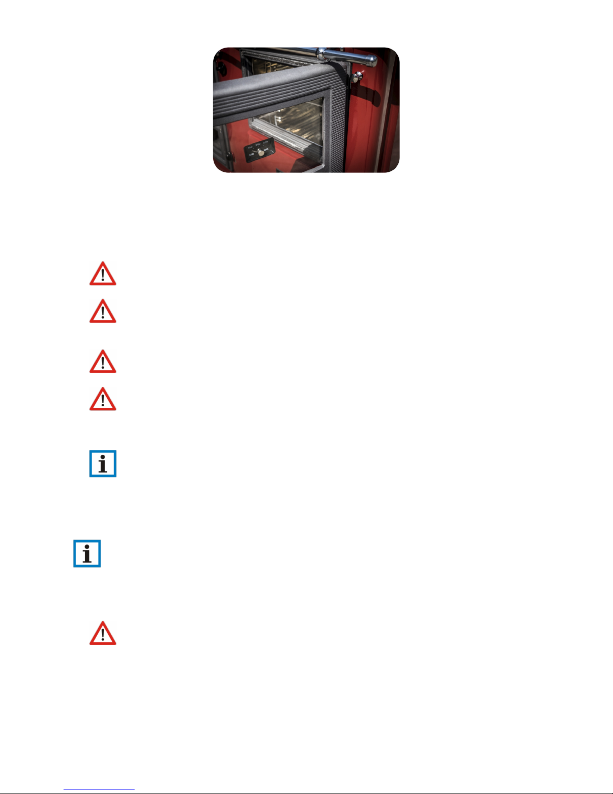
Depending on the chosen mode of operation TEMY PLUS P can perform in two modes.
1. Position 1: Predominantly Baking Mode: hot gases are directed to the oven. It is necessary to pull
the flap handle (Position 3) to yourself in order to open the passage for the flue gases around the
oven. At the same time the setting wheel (Position 4) is to be set on Position 1.
2. Position 2: Predominantly Heating Mode: hot gases are directed to the hot-water inside the boiler.
The flap handle (Position 4) is in its maximum position towards the boiler (flap is closed). At the
same time the setting wheel (Position 4) is to be set on Position 2 (as shown in the image above).
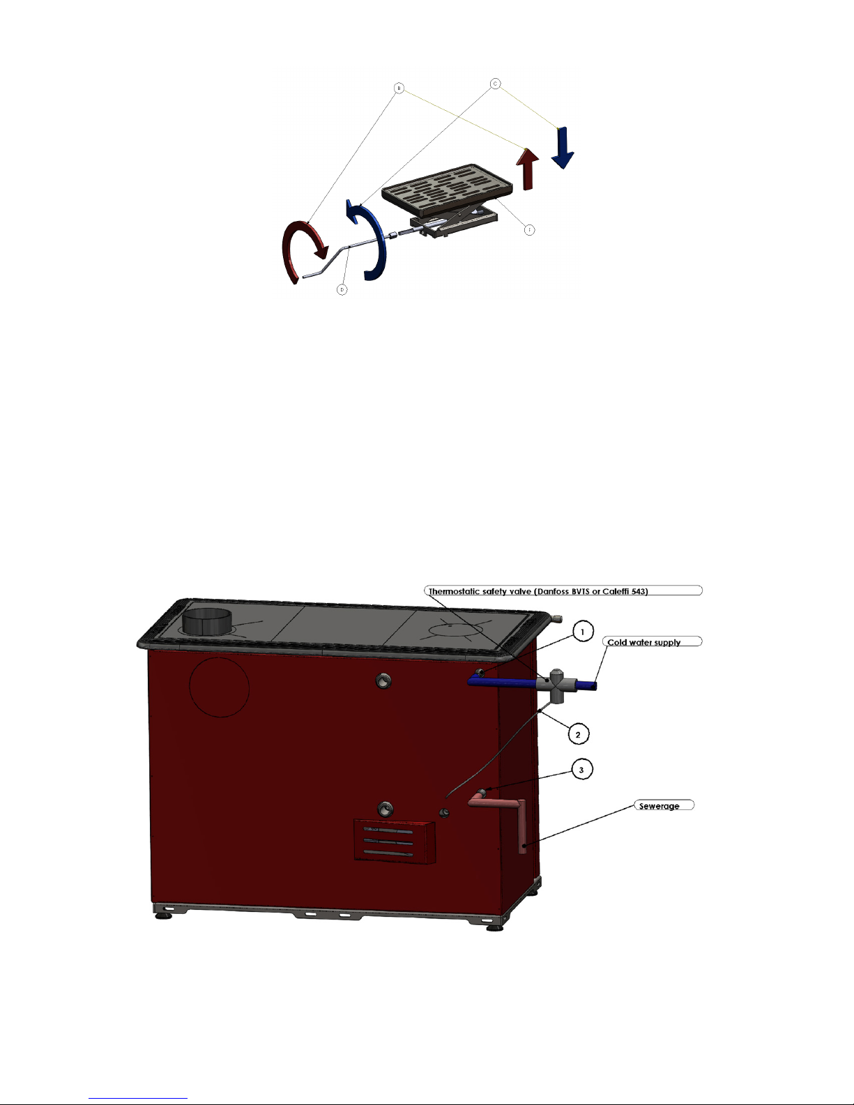
8.2 Winter or Summer Mode
When outpacking the boiler please find a screwing bar (Letter D) behind the lower door. This bar enables
the summer mode of the boiler.
During the summer, it is necessary to reduce the heating area of the boiler by lifting the bottom of
the heating chamber. In order to lift the grid (summer mode) TURN RIGHT. In order to put down
(winter mode) TURN LEFT.
15
Cooking is possible in every working mode of the stove-boiler.
Before any operation it is necessary to clean the boiler and check the pressure of the entire system.
9 Overheat protection using the thermostatic valve (closed system)
TEMY PLUS P has an embedded heat exchanger inside the heating chamber (position 12) which has to
be connected to the thermostatic overheat protection valve (such as Danfoss BVTS, Caleffi or Watts). If
the water temperature rises, the valve will open and let cold water through the heat exchanger system;
thus quickly and efficiently lowering the temperature.
The valve will operate safely regardless of the ambient temperature, and the self-acting technology means
that the valve does not recquire electricity or other forms of energy in order to work.
Description of the parts: 1. Cold water entrance toward the heat exchanger 2. Sensor of the thermostatic
valve 3. Exit for hot water from the heat exchanger
How to connect the valve:
16
•First connect the sensor (male thread 1/2”) on the marked position on the boiler - female thread
1/2”
•Now connect the cold water supply to the valve - female thread 3/4”, then connect the valve to the
position 1 (cold water entrance), the boiler should have the prepared reduction 3/4”-1/2”
•Connect the hot water exit toward the sewerage.
10 Boiler cleaning and maintenance
Do not clean the boiler while boiler is in operation. Perform cleaning only when boiler is off and
is completely cold! The use of gloves is obligatory.
It is recommended that the boiler is cleansed from ash once to two times weekly. A detailed cleansing
of the boiler should be done once a month and also when the heating season ends. Regular maintenance
extends the service life of the boiler.
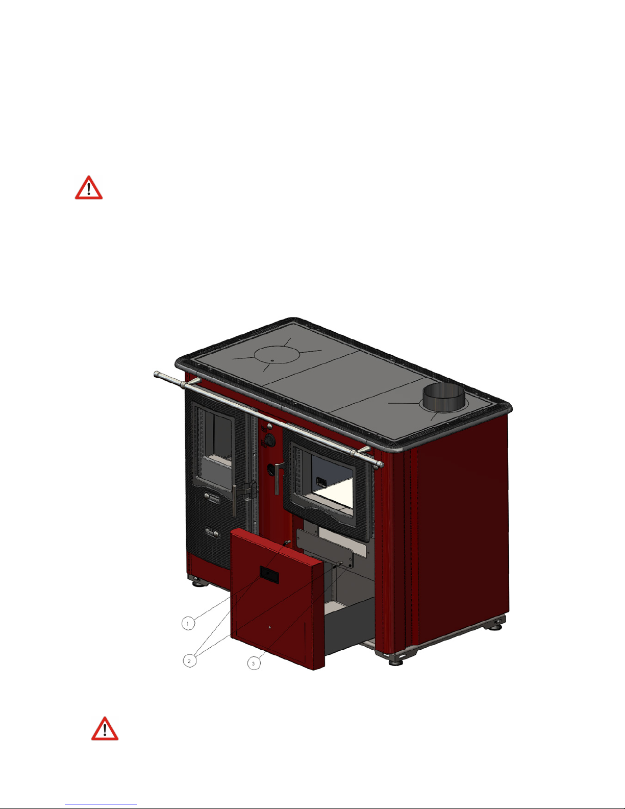
Beside the heating chamber it is also necessary to clean the area below the oven. To access this area,
please open the woodlog storage (Position 1) then unscrew the holders (Position 2 and 3).
It is also necessary to clean the area below the heating plates by simply lifting the heating plates.
Please pay attention that heating plates may fall down and hurt you.
17
Table of contents
Popular Cooker manuals by other brands


DELLA
DELLA 048-GM-48329 user manual

Logik
Logik LFTG60W12 instruction manual

Arzum
Arzum KAVURMACIM AR 2010 instruction manual

Leisure Consumer Products
Leisure Consumer Products GRB6FVK user manual

Fisher & Paykel
Fisher & Paykel OR60 models Installation instructions and user guide

Caterlite
Caterlite ce209 instruction manual


