TERSUS RS460H User manual

User Manual
Version V1.1-20220105
User Manual
For Tersus RS460H Radio
2W Wireless Data Transceiver
©2022 Tersus GNSS Inc. All rights reserved.
More details, please visit www.tersus-gnss.com

User Manual for Tersus RS460H Radio v1.1
1
Table of Content
Table of Content.......................................................................................................................1
List of Figures........................................................................................................................... 2
List of Tables.............................................................................................................................2
Revision History....................................................................................................................... 3
1. Introduction...........................................................................................................................4
1.1 Overview......................................................................................................................... 4
1.2 Specification...................................................................................................................5
1.3 Accessories.................................................................................................................... 8
2. General Operation.............................................................................................................10
2.1 Basic Operation...........................................................................................................10
2.2 Software Configuration...............................................................................................13
2.3 Installation Tips............................................................................................................15
3. Terminology........................................................................................................................16

User Manual for Tersus RS460H Radio v1.1
2
List of Figures
Figure 1.1 2W Radio RS460H........................................................................4
Figure 1.2 Serial Interface RS232................................................................. 6
Figure 1.3 410-470MHz radio whip antenna ..............................................8
Figure 1.4 Serial-5pin to DC JACK and DB9 male cable...........................9
Figure 1.5 DC JACK male with two wires.....................................................9
Figure 1.6 DB9 Female to USB Type A Male converter cable.................. 9
Figure 2.1 Front Panel of the Radio............................................................ 10
Figure 2.2 Hardware connection for software configuration....................13
Figure 2.3 TersusRadio Config Tool............................................................ 14
List of Tables
Table 1 Specifications of 2W Radio RS460H...............................................5
Table 2 Pin definition ......................................................................................6
Table 3 Default factory configuration of RS460H...................................................7
Table 4 Detailed configuration information..............................................7
Table 5 Definition for each button .........................................................10
Table 6 LED Definition................................................................................... 12
Table 7 Devices in Figure 2.2....................................................................... 13

User Manual for Tersus RS460H Radio v1.1
3
Revision History
Version
Revision Date
Change summary
1.0
20210720
Initial Release
1.0
20210903
Renew the figures
1.1
20220105
Upgrade the Figure1.1& Table 2 & Section 1.3

User Manual for Tersus RS460H Radio v1.1
4
1. Introduction
This chapter mainly introduces the overview and specification of the Tersus
2W Radio RS460H.
1.1 Overview
The Tersus 2W radio RS460H is a radio solution for both the base and the
rover. It provides reliable data communications for mission-critical applications
where a combination of stability, superior performance and long distance are
required.
The RS460H is a lightweight, ruggedized UHF receiver designed for digital
radio communications between 410 MHz and 470 MHz in 12.5/25 kHz
channels, which can be used widely in GNSS/RTK surveying and precise
positioning system applications. The RS460H is equipped with a LED display
and a keypad which is used for checking the operating status, changing the
operating channel, and transmitting power level.
Figure 1.1 2W Radio RS460H

User Manual for Tersus RS460H Radio v1.1
5
1.2 Specification
Table 1 Specifications of 2W Radio RS460H
Voltage and Power
Input voltage
DC 5 ~ 12V
Power consumption in transmitting
6W (DC 5V, transmitting power 2W)
5W (DC 5V, transmitting power 1W)
Power consumption in receiving
0.5W (DC 5V)
External Antenna
Impedance
50 ohm
VSMR
≤ 1.5
Interface
TNC female
Transmitter & Receiver
Frequency range
410MHz – 470MHz
Channel width
12.5KHz/25KHz
Modulation type
GMSK, 4FSK
Transmission power
High power (2W)
33.5 0.5dBm @ DC5V
Low power (1W)
30.5 1.0dBm @ DC5V
Power stability
1dB
Sensitivity
115dBm@BER 10-3, 9600bps
Co-channel rejection
>-12dB
Adjacent channel selectivity
>50dB@25KHz
Distance(Typical)
5-7KM
Modem
Air baud rate
19200/9600/4800bps
Serial baud rate
115200/38400(default)/19200/9600bps
Radio protocol
Transparent,TrimTalk450, TrimMark3, South, Satel
Environment
Temperature
-30C - +60C (operating)
-40C - +85C (storage)

User Manual for Tersus RS460H Radio v1.1
6
Mechanical
Dimension
107 * 62 * 26.6mm
Weight
≈200g
The serial interface provides power and data communication function for radio
equipment.Interface Type: RS232.
Figure 1.2 Serial Interface RS232
Table 2 Pin definition
Pin No.
Pin Definition
1
GND
2
GND
3
PWR
4
RXD
5
TXD

User Manual for Tersus RS460H Radio v1.1
7
Table 3 Default factory configuration of RS460H
Channel
Frequency
00
457.550MHz
01
458.050MHz
02
458.550MHz
03
459.050MHz
04
459.550MHz
05
460.550MHz
06
461.550MHz
07
462.550MHz
08
463.550MHz
09
464.550MHz
Customized frequency
410~470MHz
Table 4 Detailed configuration information
Protocol
Modulation type
Channel band
Air baud rate(bps)
TrimTalk450
GMSK
12.5 kHz
4800
GMSK
25 kHz
9600
TrimMark3
GMSK
50 kHz
19200
Transparent
GMSK
12.5 kHz
4800
GMSK
25 kHz
9600
Satel
4FSK
12.5 kHz
9600
4FSK
25 kHz
19200
South
GMSK
12.5 kHz
4800
GMSK
25 kHz
9600
GMSK
50 kHz
19200

User Manual for Tersus RS460H Radio v1.1
8
1.3 Accessories
The accessories of 2W Radio RS460H are listed below.
The 410-470MHz radio whip antenna is to be installed on 2W radio RS460H to
transmit and receive radio signal. This antenna is elastic whip structure,
resistant to bending.
Figure 1.3 410-470MHz radio whip antenna
410-470MHz Radio Whip Antenna Technical Specification
Frequency Range
410~470MHz
Bandwidth
60MHz
Polarization Mode
Vertical
Gain
2dBi
Input Impedance
50Ω
VSWR
≤2.5
Maximum Power
20W
Connector
TNC Male
Antenna Length
168mm
Antenna Weight
About 50g
Extreme Wind Speed
120 Km/h

User Manual for Tersus RS460H Radio v1.1
9
Figure 1.4 Serial-5pin to DC JACK and DB9 male cable
Figure 1.5 DC JACK male with two wires
Figure 1.6 DB9 Female to USB Type A Male converter cable
Note: The Serial-5pin to DC JACK and DB9 male cable, DC JACK male
with two wires and DB9 Female to USB Type A Male converter cable are
optional to purchase, they are not included in the package if there is no
requirement from customer.

User Manual for Tersus RS460H Radio v1.1
10
2. General Operation
Install the radio antenna before switching the radio
transceiver to transmit mode, or the radio transceiver will be
damaged.
2.1 Basic Operation
Figure 2.1 Front Panel of the Radio
Table 5 Definition for each button
Serial No.
Definition
1
Channel switching button
2
Power switching button
3
Protocol switching button
4
Current channel display
5
Power indicator (H/L)
6
Transceiver mode indicator
7
Protocol indicator
8
Power Supply Indicator

User Manual for Tersus RS460H Radio v1.1
11
The basic operations include:
1) Boot up
The radio module boots up directly when powered on.
2) Channel switching
Press the channel switching button once, the channel is increased by one. The
LED displays the current channel value, the channel display is 0 to 9, and the
default is 0.
3) Power switching
Press the power switching button once, the power is switched once. The
power indicator is steady red to indicate high power 2W, and indicator is steady
green to indicate low power 1W, and the default is high power.
4) Protocol switching
Press the protocol switching button once, the protocol is switched once. The
green light on represents Transparent, the red light on represents TT450, the
green light flashing represents South, the red light flashing represents SATEL,
the yellow light on represents TRIMMK3.
5) Transceiver mode switching
Simultaneously press and hold the channel switching button and power
switching button for 1 second to switch the transceiver mode. T is steady red

User Manual for Tersus RS460H Radio v1.1
12
for transmit mode, and red light is flashing for transmitting data. R is steady
green for receive mode, and green light is flashing for receiving data. The
default is the receive mode.
6) Restore default configuration
Simultaneously press and hold the power switching button and protocol
switching button for 1 second to recover to the default configuration.
The LED definition is shown in the table below.
Table 6 LED Definition
LED
Description
H/L
RED: 2W output is selected,
GREEN: 1W output is selected.
T/R
Blink RED: data is transmitting.
Blink GREEN: data is receiving.
TP/TT/TR3/
SUH/SAL
TP: Transparent protocol is selected.
TT: TT450 protocol is selected.
SUH: SOUTH protocol is selected.
SAL: SATEL protocol is selected.
TR3: TRIMMK3 protocol is selected.
ON
It is solid on after the power is on.
User Manual for Tersus RS460H Radio v1.1
13
2.2 Software Configuration
The detailed steps of software configuration are as follows:
1) Hardware connection
Use the accessary cables listed in section 1.3 to connect the radio to the
computer following the connection in the figure below. Power on the radio
using 5V or 12V external power supply.
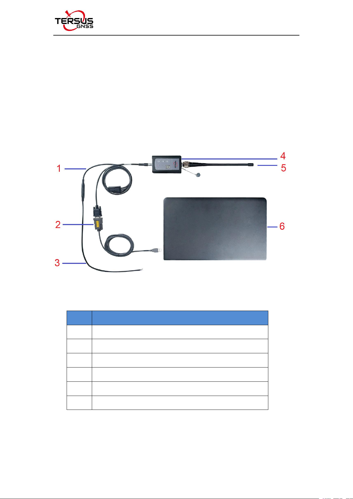
Figure 2.2 Hardware connection for software configuration
Table 7 Devices in Figure 2.2
No.
Device Name
1
Serial-5pin to DC JACK and DB9 male cable
2
DB9 Female to USB Type A Male converter cable
3
DC JACK male with two wires
4
2W Radio RS460H
5
410-470MHz radio whip antenna
6
Computer(Desktop/Laptop)

User Manual for Tersus RS460H Radio v1.1
14
2) Radio Config Tool
Open the radio configuration software ‘TersusRadio’ obtained from Tersus
support. Ensure the port is selected correctly, then click [Connect].
Figure 2.3 TersusRadio Config Tool
3) Read
After the connection is successful, click the [Read] button to read all current
configuration information.

User Manual for Tersus RS460H Radio v1.1
15
2.3 Installation Tips
2.3.1 Radio installation
As a transmission, the radio is hooked on a tripod. As a rover station, the radio
is installed in the rover station bracket.
(1) Large amount of heat would be generated when the radio is in
transmission. When the radio is working, please do not place the radio in poor
ventilated box, wrap or cover any item on the surface of the radio.
(2) In an environment with a high temperature of more than 40 °C or
intense sunlight, the surface of the radio would be hot when it is transmitting at
high power. It may cause scald if the surface of the machine is touched directly.
Please pay special attention.
2.3.2 Antenna installation
Whether the antenna is properly installed and erected would seriously affect
the transmission distance of the radio, hence the correct connection and
installation of the antenna is of high importance.
(1) It is strictly forbidden to use a damaged antenna. The output
impedance of the antenna interface of this radio is 50 ohms. Please use
antennas and feeders with input impedance of 50±2 ohms and VSWR less
than 1.5. Using an antenna that is not strictly matched with this radio would
result in a shortened transmission distance for the radio, and it is possible to
damage the radio if the mismatch is particularly serious.
(2) The original antenna of this radio is strictly matched with this radio, and
the performance meets the requirements of this radio. The original antenna of
this radio would better play the performance of this radio.

User Manual for Tersus RS460H Radio v1.1
16
(3) Under normal circumstances, the height of the antenna installed from
the ground would significantly increase the transmission distance and improve
the transmission effect.
(4) Carefully check the connection of the antenna, feeder, connector and
the components of the radio to ensure well contact and reliable connection
between the antenna and the connector of the radio.
3. Terminology
DC
Direct Current
GNSS
Global Navigation Satellite System
GPS
Global Positioning System
LED
Light Emitting Diode
SIM
Subscriber Identification Module
USB
Universal Serial BUS
VSWR
Voltage Standing Wave Ratio
Proprietary Notice
All Information in this document is subject to change without notice and does
not reflect the commitment on Tersus GNSS Inc. No part of this manual may be
reproduced or transmitted by all means without authorization of Tersus GNSS
Inc. The software described in this document must be used in terms of the
agreement. Any modification without permission from Tersus GNSS Inc. is not
allowed.
Other manuals for RS460H
1
Table of contents
Other TERSUS Radio manuals


