TERSUS RS400H3-A User manual

User Manual
Version V1.0-20220224
User Manual
For Tersus Radio RS400H3-A
Wireless Data Transceiver
©2022 Tersus GNSS Inc. All rights reserved.
Sales & Technical Support:
More details, please visit www.tersus-gnss.com

User Manual for Tersus Radio RS400H3-A V1.0
1
Revision History
Version
Revision Date
Change summary
1.0
20220224
Initial Release

User Manual for Tersus Radio RS400H3-A V1.0
2
Table of Content
Revision History....................................................................................................................... 1
Table of Content.......................................................................................................................2
List of Figures........................................................................................................................... 3
List of Tables.............................................................................................................................4
1. Introduction...........................................................................................................................5
1.1 Overview......................................................................................................................... 5
1.2 Specification...................................................................................................................6
1.3 Accessories.................................................................................................................... 8
2. General Operation.............................................................................................................11
2.1 Basic Operation...........................................................................................................11
2.2 Software Configuration...............................................................................................17
2.3 Firmware Upgrade...................................................................................................... 20
2.4 Installation Tips............................................................................................................22
2.5 Radio Repeater........................................................................................................... 24
2.6 Call Sign....................................................................................................................... 25
3. Terminology........................................................................................................................26

User Manual for Tersus Radio RS400H3-A V1.0
3
List of Figures
Figure 1.1 External Radio RS400H3-A......................................................... 5
Figure 1.2 High Gain Radio Antenna ...........................................................8
Figure 1.3 Telescopic pole for radio antenna ............................................. 9
Figure 1.4 Serial-5pin to Ext-Radio-DC-5pin & Bullet-DC Cable..............9
Figure 1.5 Bullet-DC to Alligator Clips...........................................................9
Figure 1.6 Serial-5pin to DC JACK & DB9 Male cable.............................10
Figure 1.7 DC JACK male with two wires...................................................10
Figure 1.8 DB9 Female to USB Type A Male converter cable................ 10
Figure 1.9 Configuration cable for external radio......................................10
Figure 2.1 Hardware connection for software configuration....................17
Figure 2.2 Radio configuration tool interface............................................. 18
Figure 2.3 Select serial port and baud rate................................................18
Figure 2.4 Read parameters successfully..................................................19
Figure 2.5 Channel info................................................................................. 19
Figure 2.6 Personalized settings................................................................. 19
Figure 2.7 Power Manager settings............................................................ 19
Figure 2.9 Select serial port and baud rate................................................21
Figure 2.10 Select firmware upgrade file....................................................21
Figure 2.11 Start upgrade............................................................................. 22
Figure 2.12 Upgrade firmware successfully...............................................22
Figure 2.13 Configure radio repeater..........................................................24

User Manual for Tersus Radio RS400H3-A V1.0
4
List of Tables
Table 1.1 Specifications of Radio RS400H3-A............................................ 6
Table 1.2 LED indicators................................................................................. 8
Table 2.1 Buttons description of radio RS400H3-A...................................11
Table 2.2 Devices in Figure 2.1....................................................................17

User Manual for Tersus Radio RS400H3-A V1.0
5
1. Introduction
This chapter mainly introduces the overview and specification of the Tersus
Radio RS400H3-A.
1.1 Overview
The Tersus RS400H3-A radio is a base radio solution for wireless applications.
It provides reliable data communications for mission-critical applications where
a combination of stability, superior performance and long range are required.
The RS400H3-A provides high speed, high power, wireless data links and has
been designed to survive the rigors of GNSS/RTK surveying and precise
positioning applications. Up to 35W transmit power maximizes range and
supports operation in difficult urban areas. The RS400H3-A is equipped with
OLED display and keypads which are used for checking the operating status,
changing the operating channel, and transmitting power level.
Figure 1.1 External Radio RS400H3-A
User Manual for Tersus Radio RS400H3-A V1.0
6
1.2 Specification
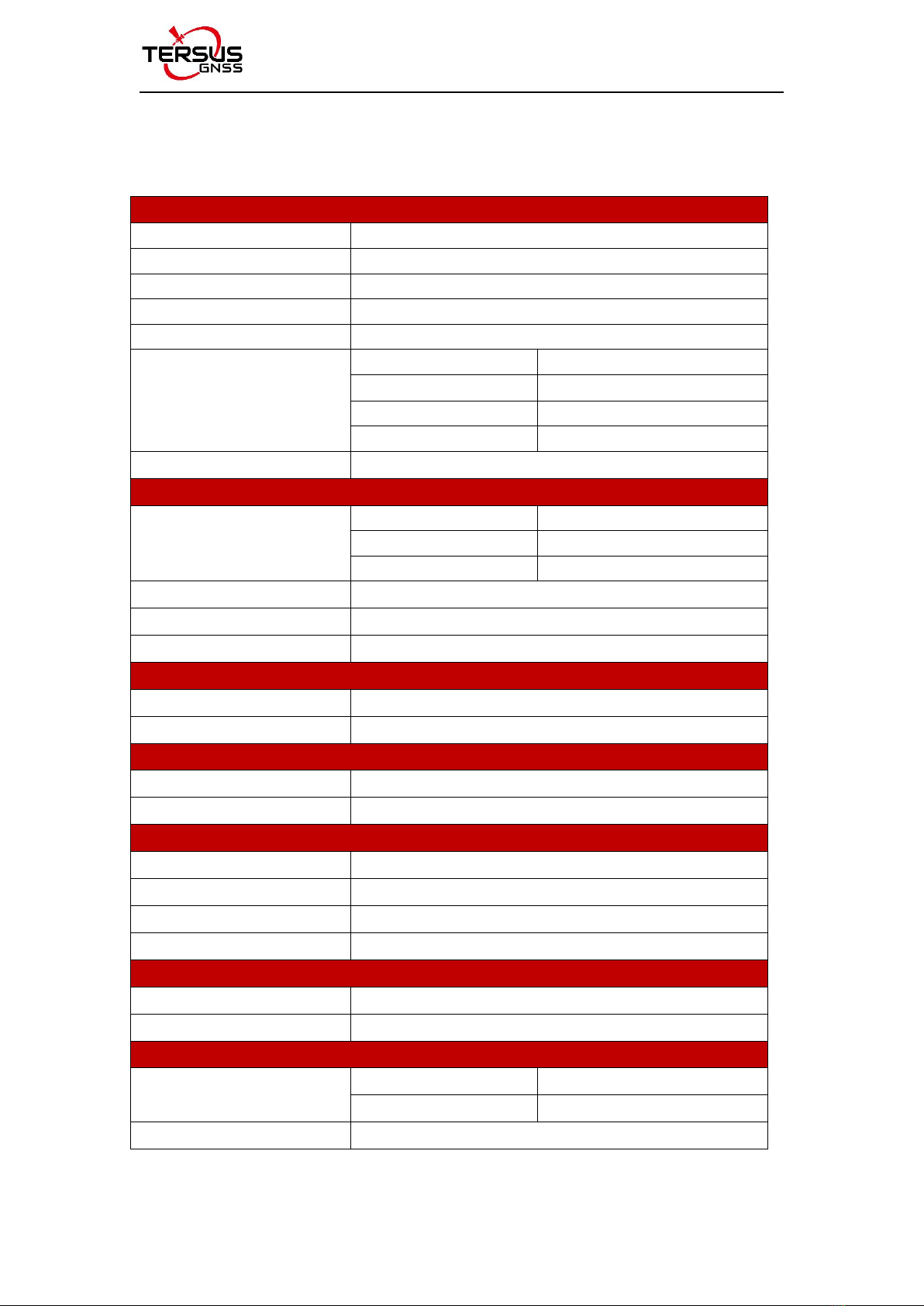
Table 1.1 Specifications of Radio RS400H3-A
General Specification
Frequency range
410~470MHz
Operating mode
Transmitter, Receiver, Radio Repeater
Channel width
12.5KHz
Channels
32
Operating voltage
9~16V DC
Power consumption
High power (35W)
85W @ DC 12V
Medium power (22W)
60W @ DC 12V
Low power (5W)
35W @ DC 12V
Standby
2W @ DC 12V
Frequency stability
≤±1.0ppm
Transmitter
RF output power
High level (35W)
45.40.5dBm @ DC 12V
Medium level (22W)
43.40.5dBm @ DC 12V
Low level (5W)
371dBm @ DC 12V
Power stability
1dBm
Adjacent channel power
>50dB
Distance(Typical)
18-21KM
Receiver
Sensitivity
<-114dBm@BER 10-3, 9600bps
Co-channel rejection
>-12dB
Antenna
Antenna Impedance
50 Ohm
Antenna Interface
TNC female
Modem
Air baud rate
4800bps, 9600bps, 19200bps
Modulation Type
GMSK/4FSK
Serial port baud rate
9600, 19200, 38400, 57600, 115200(default)bps
Protocol
TRIMTALK, TRIMMK3, TRANSEOT,SOUTH, SATEL
Bluetooth
Bluetooth Version
2.0/4.0 2.0
Bluetooth Antenna
Built-in2.0
Environmental
Temperature
Operating
-40 ~ +65C
Storage
-50 ~ +85C
Dustproof and waterproof
IP67

User Manual for Tersus Radio RS400H3-A V1.0
7
Physical Description
Dimension
175 x 130 x 86.5 mm
Weight
About 2.0kg
Data & Power interface
LEMO 5pin
Installation
Hook
Mechanical Drawing
Signal Definition
Data & power interface
View from outside to radio
Pin 1: PWR (9~16V DC)
Pin 2: Power GND
Pin 3: RXD
Pin 4: Signal GND
Pin 5: TXD
The definition of the LED indicators are as follows.

User Manual for Tersus Radio RS400H3-A V1.0
8
Table 1.2 LED indicators
LED
Description
BT
BT is Bluetooth green indicator light.
RX/TX
RX/TX is data transmitting-receiving red and green indicator light, green
indicator light represents data receiving, red indicator light represents
data transmitting.
POWER
POWER is bi-color indicator light for normal power supply and
under-voltage, green indicator light represents normal power supply, red
indicator light represents abnormal voltage
Bluetooth Module:
Users can configure and query the radio parameters by the means of
Bluetooth, Bluetooth V4.0 is supported;
1.3 Accessories
When using Radio RS400H3-A to set up a base with Oscar GNSS receiver, a
high gain radio antenna and a telescopic pole are needed which are shown as
below.
Figure 1.2 High Gain Radio Antenna
User Manual for Tersus Radio RS400H3-A V1.0
9
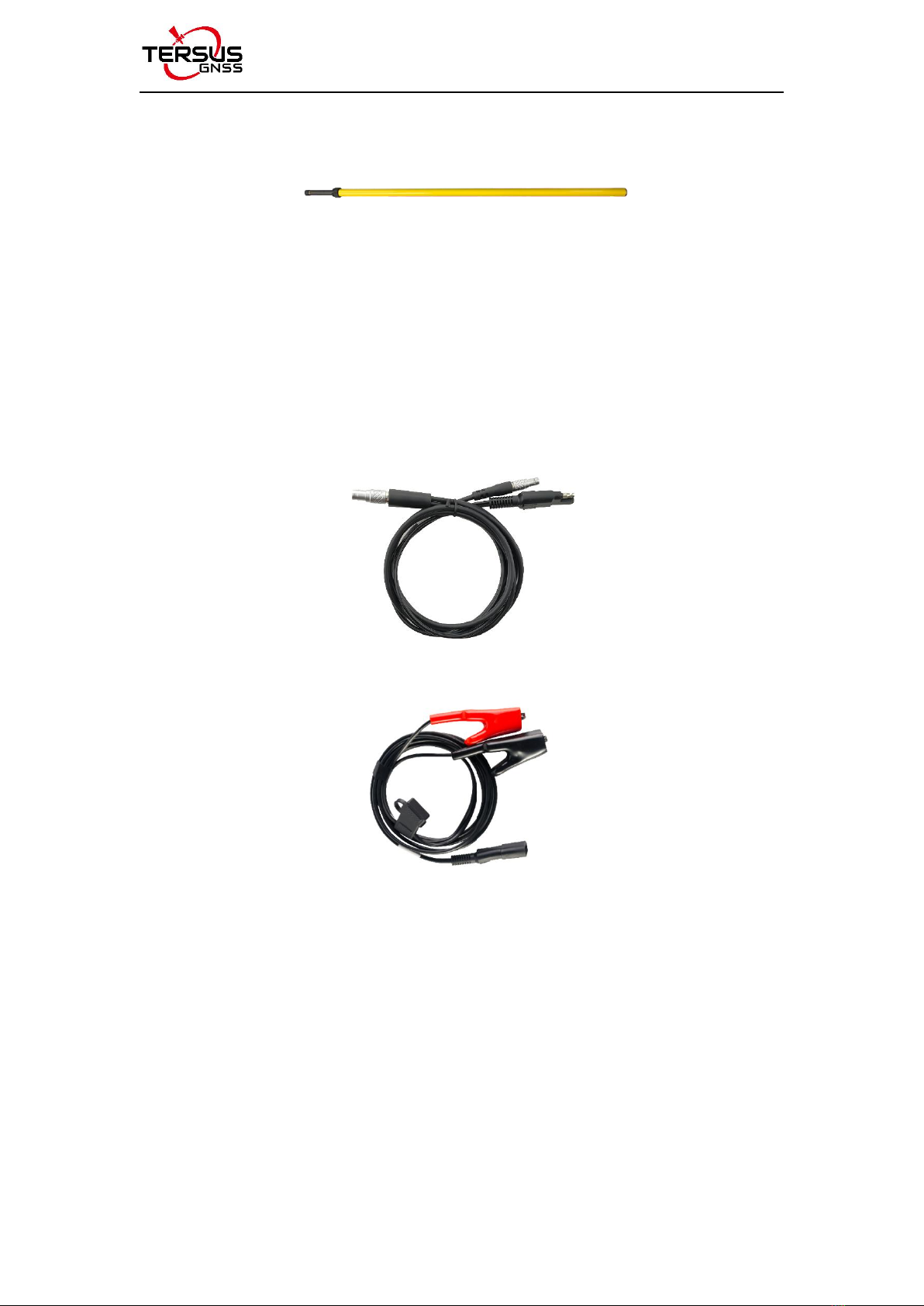
Figure 1.3 Telescopic pole for radio antenna
The following Serial-5pin to Ext-Radio-DC-5pin & Bullet-DC Cable and
Bullet-DC to Alligator Clips are used to communicate with Oscar and connect
to external power supply.
Figure 1.4 Serial-5pin to Ext-Radio-DC-5pin & Bullet-DC Cable
Figure 1.5 Bullet-DC to Alligator Clips
The Serial-5pin to DC JACK & DB9 Male cable and the DC JACK male with
two wires below are optional. It is to power Oscar using external power source
instead of the BN20 battery.
User Manual for Tersus Radio RS400H3-A V1.0
10
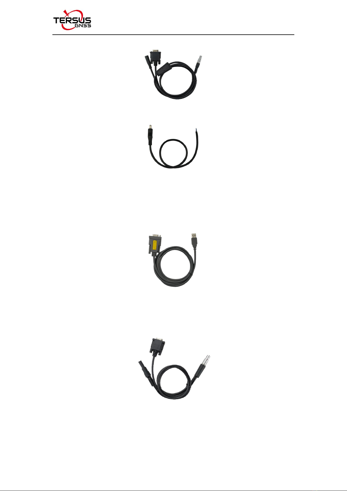
Figure 1.6 Serial-5pin to DC JACK & DB9 Male cable
Figure 1.7 DC JACK male with two wires
The DB9 Female to USB Type A Male converter cable is to convert DB9 male
to USB Type A male connector, so that it can connect to the USB port of a
computer.
Figure 1.8 DB9 Female to USB Type A Male converter cable
The Configuration cable for external radio below is used to configure
parameters of the external radio instead of the default setting.
Figure 1.9 Configuration cable for external radio

User Manual for Tersus Radio RS400H3-A V1.0
11
2. General Operation
2.1 Basic Operation
The basic operations include buttons, indicator status and device menu.
1) Buttons
There are five buttons on the radio RS400H3-A. The following table shows the
detailed description of these buttons.
Table 2.1 Buttons description of radio RS400H3-A
Icon
Button
Function
Power
It is used to control radio power-on and power-off, with specific
functions as follows:
Short press the power button for about 1 second to power on,
the green power indicator light illuminates when successful
power-on (under normal power supply).
While power-on, long press the power button for 3 seconds to
power off, the power indicator light turns off and the display is
off.
Parameter confirmation in the menu.
Left
Switch over various functions in the menu.
Right
Up
Select corresponding item in the current menu.
Down
2) Indicator status
Normal power on/off of the radio has memory function, abnormal power on/off
does not have memory function. The detailed functions are as follows.

User Manual for Tersus Radio RS400H3-A V1.0
12
In the case of abnormal shutdown for the last time, power on again after
outage, the radio powers on automatically;
In the case of normal shutdown for the last time, short press the power
button about 1 second to power on the radio;
If the voltage is lower than the under-voltage threshold value (11.0V by
default, depending on the user’s actual setting value), the red power
indicator light flickers twice in one second;
If the voltage is lower than the forbidden threshold value (10.2V by default,
depending on the user’s actual setting value), the red power indicator light
flickers once in one second;
If the voltage is higher than the under-voltage threshold value (11.0V by
default, depending on the user’s actual setting value), the green power
indicator light illuminates constantly;
When the voltage alarm appears, if it is under-voltage alarm, it is needed
to add 0.3V based on the under-voltage threshold value to resume to the
normal operating voltage (the green power indicator light illuminates
constantly);
Note:
Abnormal shutdown means not powering off by long pressing the power
button, for example, directly disconnecting power;
Normal shutdown refers to power off by long pressing the power button.
3) Device menu
The device menu is divided into two categories: basic radio parameter menu
and other features/functions menu.
Device information
Under the information bar, the current channel number, current transmitting
frequency, current receiving frequency, current protocol, current transmitting
User Manual for Tersus Radio RS400H3-A V1.0
13
power, battery status, device model, firmware version, hardware version and
serial number are displayed.
Channel and frequency
Under this menu, you can set up the current transmitting/receiving frequency,
select required communication frequency through up and down buttons, and
press the power key to select this frequency as the current communication
frequency, the star character “*” will appear after selection.
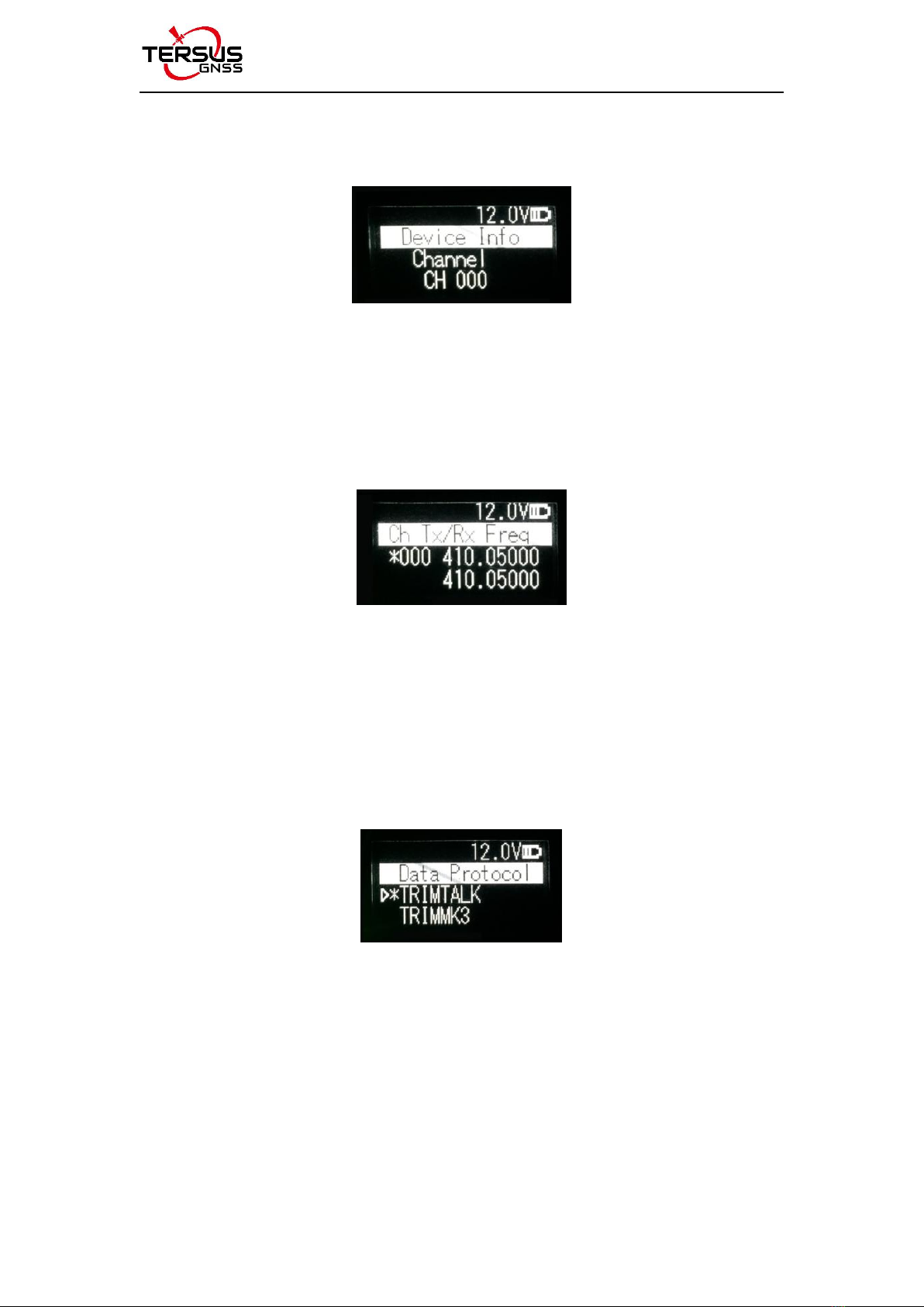
Data protocol
Under this menu, you can set up the current communication protocols such as
TRANSEOT, TRIMTALK and TRIMMK3. Select required communication
protocol through up and down buttons, and press the power key to select this
protocol as the current communication protocol, the star character “*” will
appear after selection.
Note: After changing the protocol, you need reselect the air baud rate
supported by the current protocol in the menu of “wireless link rate”.
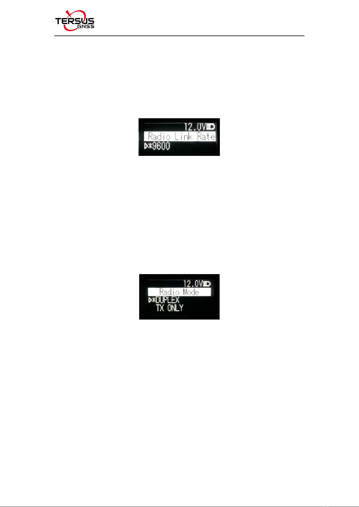
Air baud rate
Under this menu, you can set up the current communication air baud rate.
User Manual for Tersus Radio RS400H3-A V1.0
14
Different protocols support different types of air baud rates. For example,
TRANSEOT supports 4800 and 9600 bps, while TRIMMK3 supports 19200bps.
Select required air baud rate through up and down buttons, and press the
power button to select this air baud rate as the current communication air baud
rate, the star character “*” will appear after selection.
Transmitting/Receiving mode
In this menu column, you can set up the current radio transmitting/receiving
mode. Now, four types of transmitting/receiving modes are supported:
transmitting-receiving, single transmitting, single receiving and relaying mode.
Select required transmitting/receiving mode through up and down buttons, and
press the OK key to select this transmitting/receiving mode as the current
communication transmitting/receiving mode, the character of“*”will appear
after selection
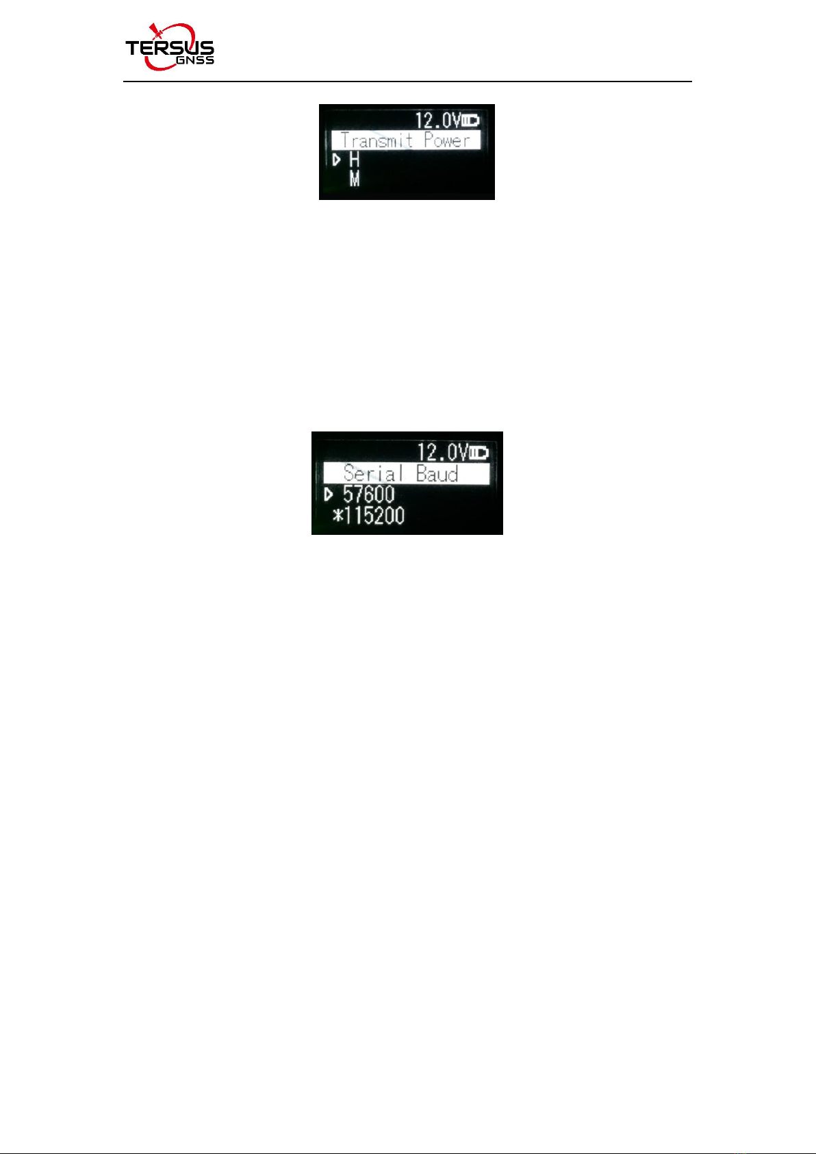
Transmit power
Under this menu, you can set up the current wireless transmitting power level.
Currently three levels of power, high, medium and low, are supported. These
three levels of power values can be customized according to the demands of
users. Select required transmitting power through up and down buttons, and
press the power button to select this transmitting power as the current
communication transmitting power, the star character “*” will appear after
selection.
User Manual for Tersus Radio RS400H3-A V1.0
15
Serial baud rate
Under this menu, you can set up the current serial port communication baud
rate. Currently it supports following baud rates: 9600, 19200, 38400, 57600,
and 115200 bps. Select required serial port communication baud rate through
up and down buttons, and press the power button to select this serial port
communication baud rate as the serial port baud rate of the current
communication, the star character “*” will appear after selection.
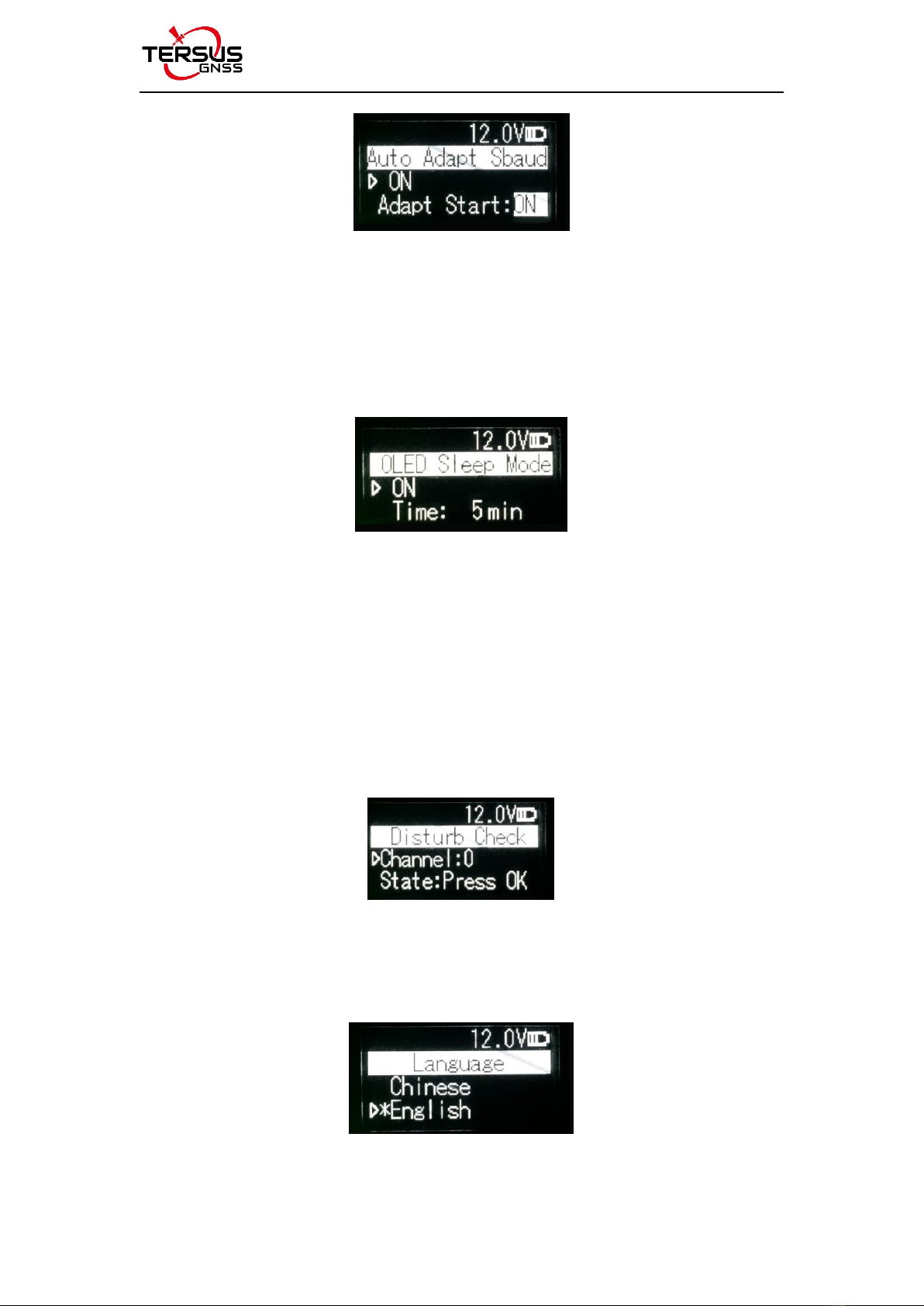
Serial baud rate self-adaption
Under this menu, there are two options: self-adaptive master switch and
triggering enabling. The former has memory function, if turning on the switch,
ON is displayed on the menu; if off, then OFF is displayed. Self-adaptive
triggering enabling does not have memory function, the system remains in the
power up status after power-on; only if the self-adaptive master switch has
been turned on can the adaptive function of serial port baud rate work
normally.
If the serial port baud rate is successfully self-adaptive, a message box pops
up indicating successful self-adaptive matching, meanwhile, self-adaptive
triggering enabling stops automatically. If the serial port baud rate is not
successfully self-adaptive, this function is always operating.
User Manual for Tersus Radio RS400H3-A V1.0
16
OLED sleep mode
Only if the “Function” is switched to “On” can the OLED display enter the sleep
mode. Sleep time has the following levels: 1min, 5min, 10min, 15min, 20min,
25min, and 30min.
Note: After the OLED display enters sleep, it can be waken up through button
and pop-up message.
Interference detection
To detect whether there is any interference in the current channel, you can
modify the detection channel number manually and press the power button for
detection. There are three levels of detection result: superior, moderate, poor.
Language
Set the display language, Chinese and English are supported.
User Manual for Tersus Radio RS400H3-A V1.0
17
2.2 Software Configuration
The detailed steps of software configuration are as follows:
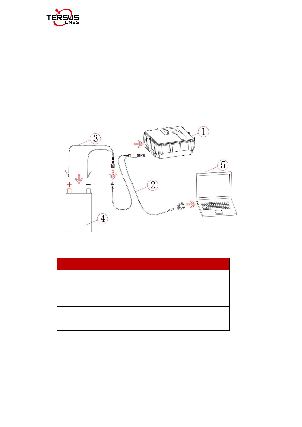
1) Hardware connection
Use the accessary cables listed in section 1.3 to connect the radio to the
computer following the connection in the figure below. Power on the radio
using 12V external power supply.
Figure 2.1 Hardware connection for software configuration
Table 2.2 Devices in Figure 2.1
No.
Device Name
1
Radio RS400H3-A
2
Configuration cable for external radio
3
Bullet-DC to Alligator Clips
4
12V external power supply
5
Computer (Desktop/Laptop)
2) Radio Config Tool installation
Run the radio config tool installation file as administrator, and click “Next” until
installation is completed. The shortcut will appear on the desktop. Right-click

User Manual for Tersus Radio RS400H3-A V1.0
18
the shortcut on the desktop and select “Run as administrator”, the software
interface is shown as below.
Figure 2.2 Radio configuration tool interface
Note:
During the use of the configuration tool for radio parameter configuration and
query, the radio is not allowed to enter the background parameter configuration
mode by the buttons and OLED display.
3) Radio parameter query
After the connection is successful, click the [Read] and select the correct serial
port number and the current operating baud rate in the pop-out window. Then
click [Connect] and [Read] on the right to read the radio configuration
parameters.
Figure 2.3 Select serial port and baud rate

User Manual for Tersus Radio RS400H3-A V1.0
19
Figure 2.4 Read parameters successfully
Figure 2.5 Channel info
Figure 2.6 Personalized settings
Figure 2.7 Power Manager settings
Table of contents
Other TERSUS Radio manuals


