TES TES-2730 User manual

DIGITAL
MULTIMETER
TES-2730
INSTRUCTION MANUAL
TES ELECTRICAL ELECTRONIC CORP.

CONTENTS
TITLE PAGE
SAFETY INFORMATION ................................................................ 1
I. SPECIFICATIONS ........................................................................ 2
1-1 General Specifications ......................................................... 2
1-2 Electrical Specifications ....................................................... 4
II. NAME OF PARTS AND POSITIONS .......................................... 8
III. PRECAUTIONS AND PREPARATIONS FOR
MEASUREMENT ........................................................................ 10
IV. MEASUREMENTS ..................................................................... 11
4-1 DC Voltage Measurement ................................................... 11
4-2 AC Voltage Measurement ................................................... 12
4-3 DC Current Measurement ................................................... 12
4-4 AC Current Measurement .................................................... 13
4-5 Resistance Measurement .................................................... 13
4-6 Capacitance Measurement .................................................. 14
4-7 Frequency Measurement ..................................................... 14
4-8 Temperature Measurement ................................................. 14
4-9 Diode Tests .......................................................................... 15
4-10 Continuity Measurement .................................................... 15
V. BATTERY & FUSE REPLACEMENT ......................................... 16
5-1 Battery Check-up & Replacement ....................................... 16
5-2 FUSE Replacement ............................................................. 16
VI. OPTIONAL ACCESSORY ......................................................... 19

1
SAFETY INFORMATION
Read the following safety information carefully before attempting to
operate or service the meter.
To avoid damages to the instrument do not apply the signals which
exceed the maximum limits shown in the technical specifications tables.
Never measure current while the test leads are inserted into the input
jacks.
Do not use the meter or test leads if they look damaged. Use extreme
caution when working around bare conductors or bus bars.
Accidental contact with the conductor could result in electric shock.
Use the meter only as specified in this manual ; otherwise, the protection
provided by the meter may be impaired.
Read the operating instructions before use and follow all safety
information.
Caution when working with voltages above 60V DC or 30 V AC RMS.
Such voltages pose a shock hazard.
Before taking resistance measurements or testing acoustic continuity,
disconnect circuit from main power supply and all loads from circuit.
Safety symbols:
Caution refer to this manual before using the meter.
Dangerous voltages.
Meter is protected throughout by double insulation or
reinforced insulation.
When servicing, use only specified replacement parts.
Comply with EN-61010-1
2
1. SPECIFICATIONS
1-1 General Information
Environment conditions :
Installation Categories
II
Pollution Degree 2
Altitude up to 2000 meters
Indoor use only
Relatively humidity 80% max
Operation Ambient 0〜40℃
maintenance & Clearing :
Repairs or servicing not covered in this
manual should only be performed by
qualified personal.
Periodically wipe the case with a dry cloth
and detergent.
Do not use abrasives or solvents on this
instruments.
Operating Principle :Dual slope integration.
Numerical Display :3 1/2 digit liquid crystal display (LCD)
7mm height. maximum reading 1999 .
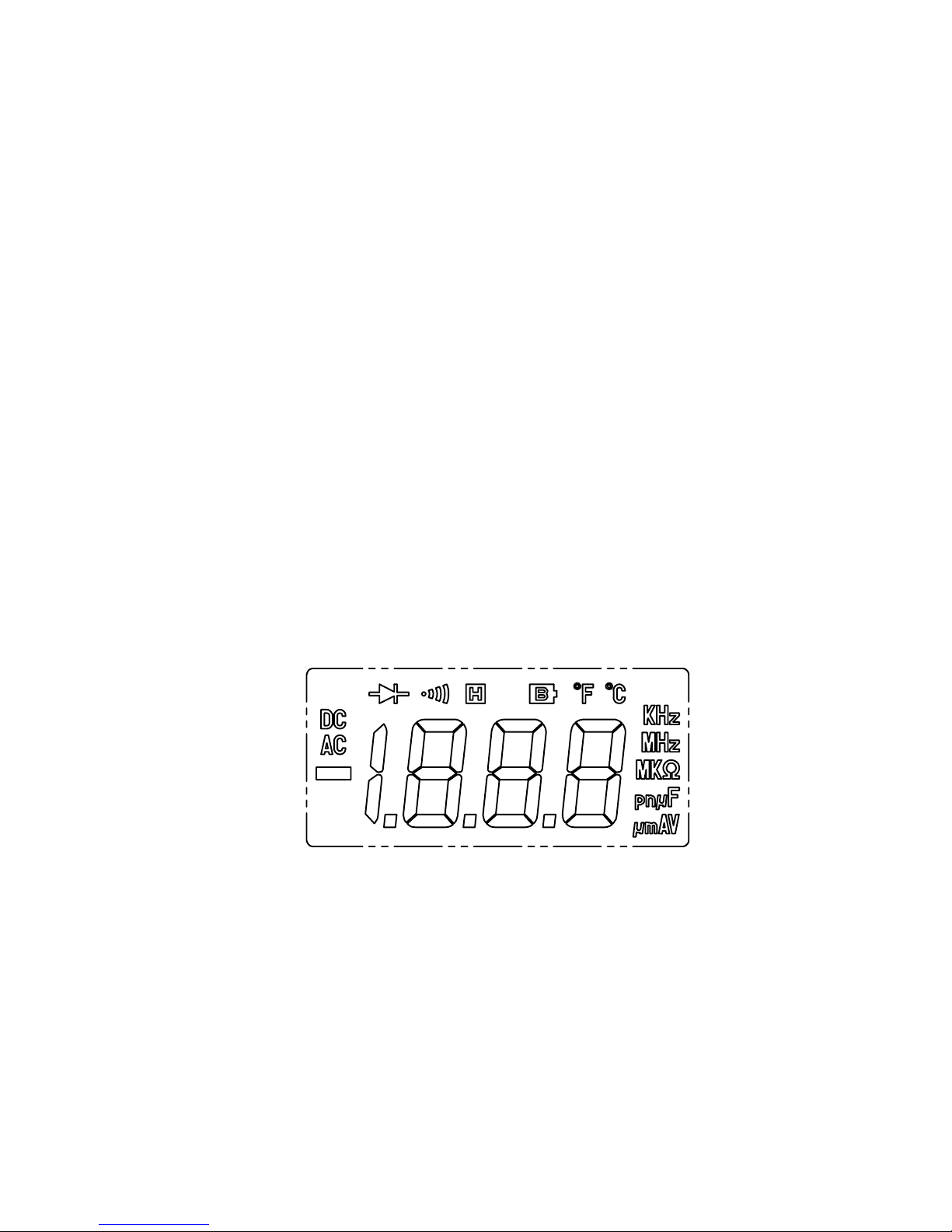
Unit and Sign Display :
Fig-1

3
DC Direct current or voltage
AC Alternating current or voltage
Negative polarity
■Decimal point
V Volts
mV Millivolts ( 1×10
-3
volts )
A Ampere ( amps ). Current
uA Microamperes ( 1×10
-6
amps )
uF Microfarads ( 1×10
-6
Farads ), Capacitance.
nF Nanofarads ( 1×10
-9
Farads ), Capacitance.
pF Picofarads ( 1×10
-12
Farads ), Capacitance.
ΩOhms. Resistance
KΩKilohms ( 1×10
3
ohms ). Resistance
MΩMegohm ( 1×10
6
ohms ). Resistance
MHz Megahertz ( 1×10
6
ohms ). Frequency
KHz Kilohertz ( 1×10
3
cycles / sec ). Frequency
℃Celsius temperature scale
℉Fahrenheit temperature scale
Low Battery
Data Hold
Continuity Beeper
Diode
Range Selection :All ranges are measured by single Range
switch operation.
Over Range Indication :“
OL
“ appears on the display.
Low Battery Indication :The is displayed when the battery
voltage drops below the operating voltage.
Sampling Rate :2.5 time per second except in Freq. Mode.
1 time per second in Freq. Mode.
Power Requirements :9-Volt battery (NEDA or JIS 006p IEC6f22)
Battery Life ( typical ) :Approx. 60hours. (Alkaline Battery)
Operating Temperature :0℃to 40℃( 32℉to 104℉)

4
and Humidity RH below 80%
Storage Temperature :-10℃to 60℃( 14℉to 140℉)
and Humidity RH below 70%
Dimensions :180 (L) ×82 (W) ×38(H) mm
7.09”(L)×3.2”(W)×1.5”(H)
Weight :365g
Accessories :Test leads (pair), Operating Instruction,
Spare fuse ( 0.5A / 250V ), Software, Battery,
RS-232C Cable, 9pin to 25pin Gender
Changer.
Optional Accessories :K type thermocouple.
1-2 Electrical Specifications
Accuracies are ±(...% of reading + ...digits) at 23℃± 5℃,below 80% RH.
DC Voltage
Range Resolution Accuracy Input
Impedance
Overload
Protection
200m
V 0.1mV 600Vrms
2V 1mV
20V 10mV
200V 100mV
0.5%+1
600V 1V 0.5%+2
10MΩ
750Vrms
AC Voltage ( 50Hz to 500Hz )
Range Resolution Accuracy Input
Impedance
Overload
Protection
200mV 0.1mV 600Vrms
2V 1mV
20V 10mV
1%+5 10MΩ
750Vrms

5
200V 100mV
600V 1V 1.2%+5
DC Current
Range Resolutio
n Accuracy Burden
Voltage Overload Protection
200uA 0.1uA
2mA 1uA
20mA 10uA
200mA 100uA
1%+1 0.35V 0.5A / 250V Fast
Blow Fuse & Diode
20A 10mA 1.2%+3 0.8V
20A / 380V Fast Blow
Fuse
20A for 30sec. max.
10A continuity.
AC Current ( 50Hz to 500Hz )
Range Resolutio
n Accuracy Burden
Voltage Overload Protection
200uA 0.1uA
2mA 1uA
20mA 10uA
200mA 100uA
1.2%+3 0.35V 0.5A / 250V Fast
Blow Fuse & Diode
20A 10mA 1.5%+5 0.8V
20A / 380V Fast Blow
Fuse
20A for 30sec. max.
10A continuity.
6
Resistance ( Ω)
Range Resolution Accuracy Max. Open
Circuit Voltage
Overload
Protection
200Ω0.1Ω3.2V
2KΩ1
Ω
20KΩ10Ω
200KΩ100Ω
2MΩ1KΩ
0.8%+2
20MΩ10KΩ1.5%+3
0.5V 600Vrms
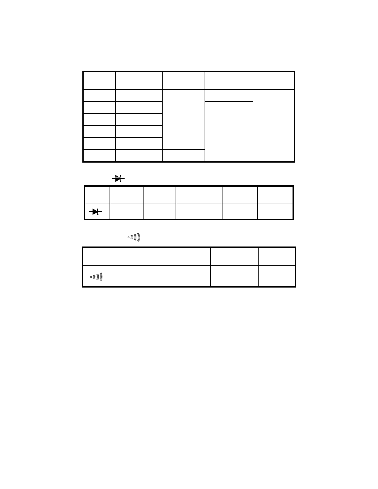
Diode ( )
Range Resolution Accuracy Max. Open
Circuit Voltage
Max. Test
Current
Overload
Protection
1mV 2%+ 2 3.2V 1.0mA 600Vrms
Continuity ( )
Range Operation Resolution Max. Open
Circuit Voltage
Overload
Protection
Continuity audible tone for
tested resistance below 30Ω3.2V 600Vrms
7
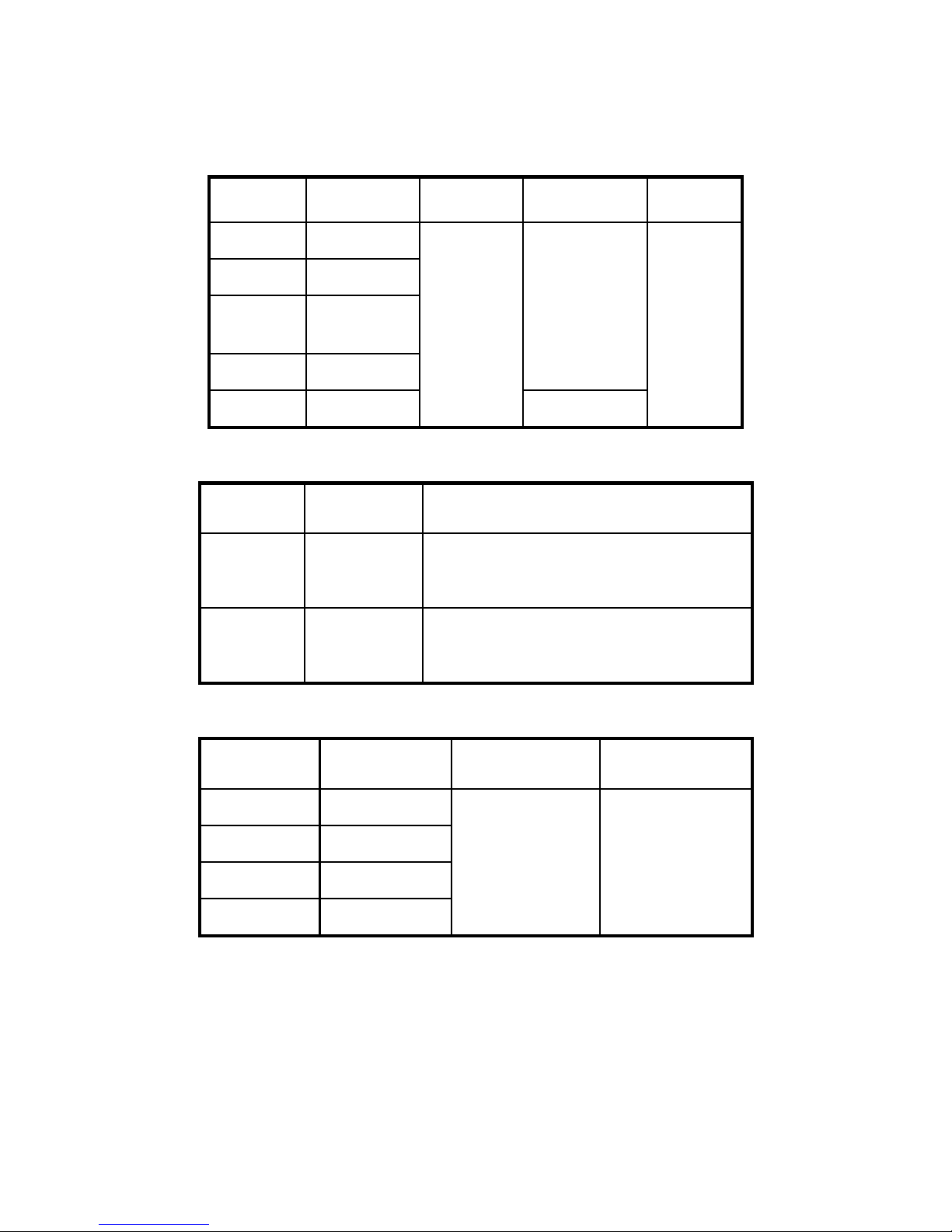
Frequency ( Hz ) ( Test Range 10Hz - 10MHz Auto Range )
Range Resolution Accuracy Sensitivity
Overload
Protection
2KHz 1Hz
20KHz 10Hz
200KH
z 100Hz
2MHz 1KHz
1.5Vrms
10MHz 10KHz
0.5%+2
3Vrms
600Vrms
Temperature Probe used : K (CA) type sensor
Range Resolution Accuracy
℃0.1/1℃
0℃〜200℃±(0.5%+1.5℃)
-50℃〜0℃±( 1% + 2℃)
200℃〜1300℃±( 1% + 2℃)
℉0.1/1℉
0℉〜200℉±( 0.5%+3℉)
-58℉〜0℉±( 1% + 5℉)
200℉〜1999℉±( 1% + 4℉)
Capacitance (F)
Range Resolution Accuracy Test Frequency
2000pF 1pF
200nF 100pF
2uF 1nF
20uF 10nF
3%+10 400Hz
8
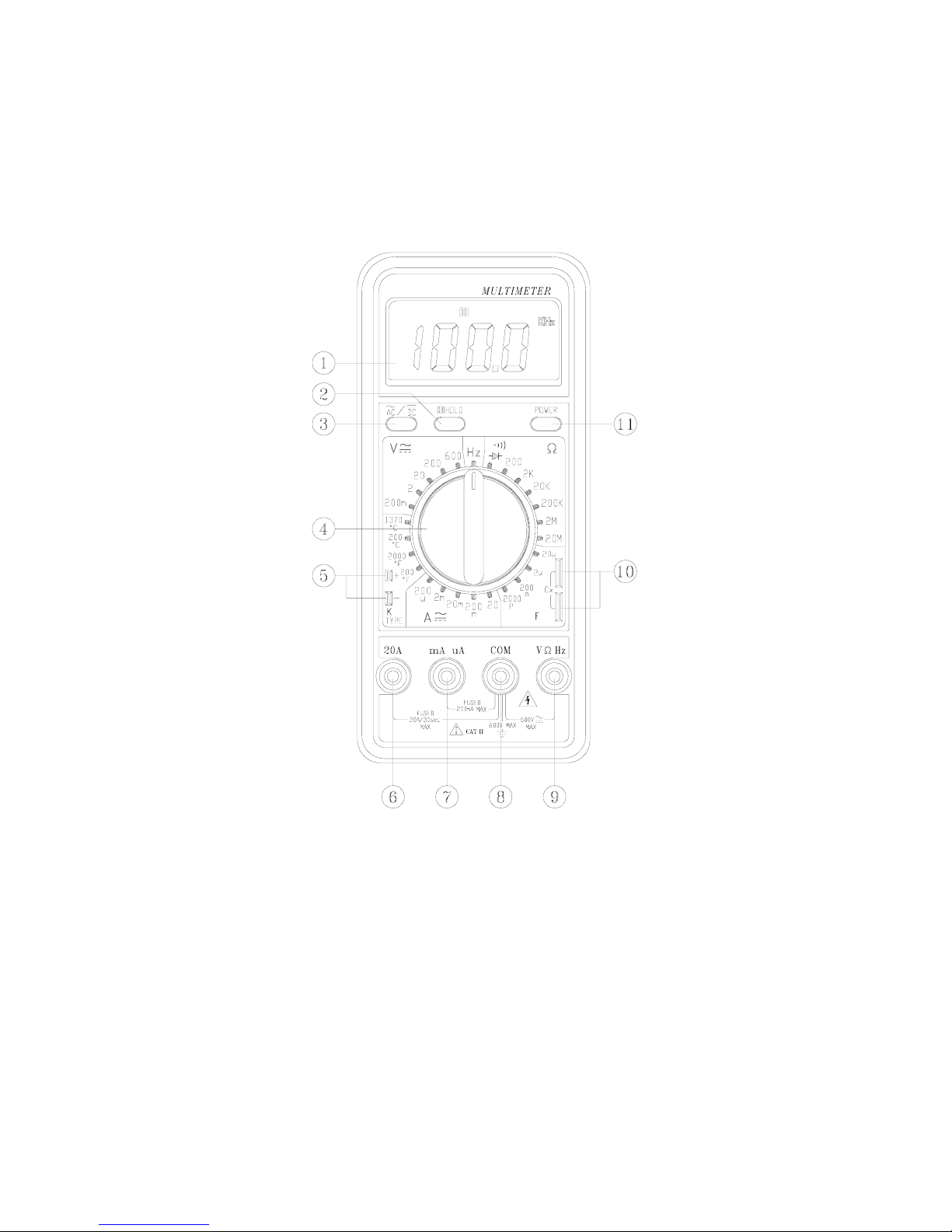
II.
NAME OF PARTS AND POSITIONS
Fig-2

9
LCD Display :
Measured values, unit symbols and decimal points are displayed.
Data Hold Button :
Push the Button to hold the reading and sign will appear . Push again, to
release the holding.
AC/DC Function Button :
To select function for measuring DC voltage, DC current, AC voltage ,
AC current.
Range Selector Switch :
For range selection.
Temperature Measuring Connector :
To insert K ( CA ) type sensor for temperature measurement.
20A Measuring Connector :
To connect positive lead (red test lead) for current measurement below
20A.
mA and uA Measuring Connector :
To connect positive lead (red test lead) for current measurement below
200mA.
COM Measuring Connector :
To connect negative lead ( black test lead ) for voltage, current ,
resistance, diode, frequency , and continuity measurement.
“ V-Ω-Hz ” Measuring Connector :
To connect positive lead ( red test lead ) for voltage, resistance, diode ,
frequency, and continuity measurement.

10
Capacitance Measuring Connector :
To insert capacitor pins for capacitance measuring.
11
Power ON/OFF Button :
For Power ON and Power OFF Selection.
12
RS-232C interface Connector :
To connect the RS-232C cable to the terminals built into the PC and
meter.
III. PRECAUTIONS AND PREPARATIONS FOR
MEASUREMENT
1). DO NOT attempt to take any voltage or current measurement that
exceed the maximum range of this instrument.
2). Be sure that battery is correctly placed in the case and connected
to the battery snap.
3). Make certain the range selected is greater than circuit current or
voltage prior to attempting measurement.
When changing range it always breaks contact from the circuit with
one of the test leads.
4). Check the input terminal position for red test lead according to the
measurement ranges.
5). DO NOT measure if the rear cover of Multimeter is not secured.
6). When finish the measurement, turn OFF the power.
7). To avoid leakage problem, be sure to remove the battery when it is
not to be used for a long time.
8). DO NOT use or store the instrument in a high temperature of high
humidity environment.
9). DO NOT check resistance in a circuit while power is on or before
circuit capacitors are discharged.

11
IV.MEASUREMENTS
4-1 DC Voltage Measurement
1). Connect red test lead to “ V-Ω-Hz “ terminal and black test lead
to “ COM “ terminal.
2). Set range switch to desired V range and set DC / AC push
switch to DC position.
3). Connect Test prods of test leads IN PARALLEL to the circuit
being measured.
4). Read the voltage value displayed on LCD.
NOTE :
If the voltage is unknown before measurement, first , set
the function switch to the high-test range then, change to a
lower range, step by step.
When the “ OL “ is displayed, the measuring circuit is
overloaded. The function switch must be set to a higher
range.
Always avoid contact with high tension circuits when
measuring high voltage.

12
4-2 AC Voltage Measurement
1). Connect red test lead to “ V-Ω-Hz “ terminal and black test lead
to “ COM “ terminal.
2). Set range switch to desired V range and set DC / AC push
switch to AC position.
3). Connect Test prods of test leads IN PARALLEL to the circuit
being measured.
4). Read the voltage value displayed on LCD.
NOTE :
See DC voltage measurement NOTE.
4-3 DC Current Measurement
1). Connect red test lead to “mA“ Terminal for Current
measurements up to 200mA. (For measuring Current between
200mA to 20A, Connect red test lead to “20A“ terminal.) Connect
black test lead to “COM” terminal.
NOTE :
For measuring current between 10A to 20A, maximum
measuring time is 30 second.
2). Set range switch to desired A range and set DC / AC push
switch to DC position.
3). Cut the power to the circuit to be tested and Connect the
instrument IN SERIES with the circuit ; with the black test lead on
the negative “ -“ side and the red lead on the positive “+” side
being measured.
4). Apply power and read the current value displayed on LCD.

13
4-4 AC Current Measurement
1). Connect red test lead to “mA“ Terminal for Current
measurements up to 200mA. (For measuring Current between
200mA to 20A, Connect red test lead to “20A“ terminal.) Connect
black test lead to “COM” terminal.
NOTE :
For measuring current between 10A to 20A, maximum
measuring time is 30 second.
2). Set range switch to desired A range and set DC / AC push
switch to AC position.
3). Cut the power to the circuit to be tested and Connect the
instrument IN SERIES with the circuit ; with the black test lead on
the negative “ -“ side and the red lead on the positive “+” side
of the circuit being measured.
4). Apply power and read the current value displayed on LCD.
4-5 Resistance Measurement
WARNING
Before taking any in-circuit resistance measurement remove
power from the circuit being tested and discharge all Capacitors.
1). Connect red test lead to “ V-Ω-Hz “ terminal and black test lead
to “ COM “ terminal.
2). Set range switch to desired ΩRange.
3). Connect the test leads to the circuit being measured and read the
resistance value displayed on LCD.

14
4-6 Capacitance Measurement
1). Set range switch to desired capacitor (F) position.
2). Insert the capacitor pins into capacitance connector for
measurement.
3). Read the capacitance on LCD.
4-7 Frequency Measurement
1). Set range switch to the Hz position.
2). Connect red test lead to “ V-Ω-Hz “ terminal and black test lead
to “ COM “ terminal.
3). Connect test prods of test Leads to the circuit to be measured.
4). Read the frequency value (Hz) displayed on LCD.
4-8 Temperature Measurement
1). Set range switch to the TEMP ℃or ℉range.
2). Connect the K-type thermocouple probe to the temperature
measurement jack.
3). Perform measurements by contacting the object being measured
with the probe sensor.

15
4-9 Diode Tests
WARNING
Before taking any in-circuit measurement remove power from
the circuit being tested and discharge all capacitors.
1). Connect red test lead to “ V-Ω-Hz “ terminal and black test lead
to “ COM “ terminal.
2). Set range switch to diode test ( ) position.
3). Connect the red test lead to the anode side and black test lead to
the cathode side of the diode being tested.
4). Read forward voltage (Vf) value displayed on LCD.
5). If test leads are connect to the diode in a way different procedure
(3). The reading should be nearly equal to the reading without
any diode being connected. This can be used for distinguishing
anode and cathode poles of a diode.
4-10 Continuity Measurement
1). Connect red test lead to “ V-Ω-Hz “ terminal and black test lead
to “ COM “ terminal.
2). Set range switch to the ( ) position.
3). Remove power from the circuit being tested and discharge all
capacitors.
4). Connect the test lead to the circuit being measured.
5). When the impedance of a circuit is below 30 Ω. Continuous
beeping tone shall be heard.
NOTE:
Continuity Test is available to check open / short circuit. If precise
data of resistance is needed, use
Ω
function.

16
V. BATTERY & FUSE REPLACEMENT
5-1 Battery Check-up & Replacement
WARNING
To prevent electrical hazard or shock turn off Multimeter and
disconnect test leads before removing back cover.
1). As battery power is not sufficient. will be displayed on LCD.
Replacement with a new 9V battery is required.
2). After test leads are disconnected and the Multimeter is furred off,
remove the bottom cover.
3). Remove battery from the holder and replace it with a standard 9 -
Volt transistor battery.
4). Replace the battery cover.
5-2 FUSE Replacement
WARNING
To prevent fire , use 0.5A / 250V size 5φ×20mm or 20A / 380V
size 6φ×30.8mm fast blow type fuse.
1). Turn off the Multimeter and disconnect test leads.
2). Remove back cover with a screw driver.
3). Referring to Figure 4, remove the defective fuse and install a new
fuse of the same size and rating.
4). Replace the battery cover.
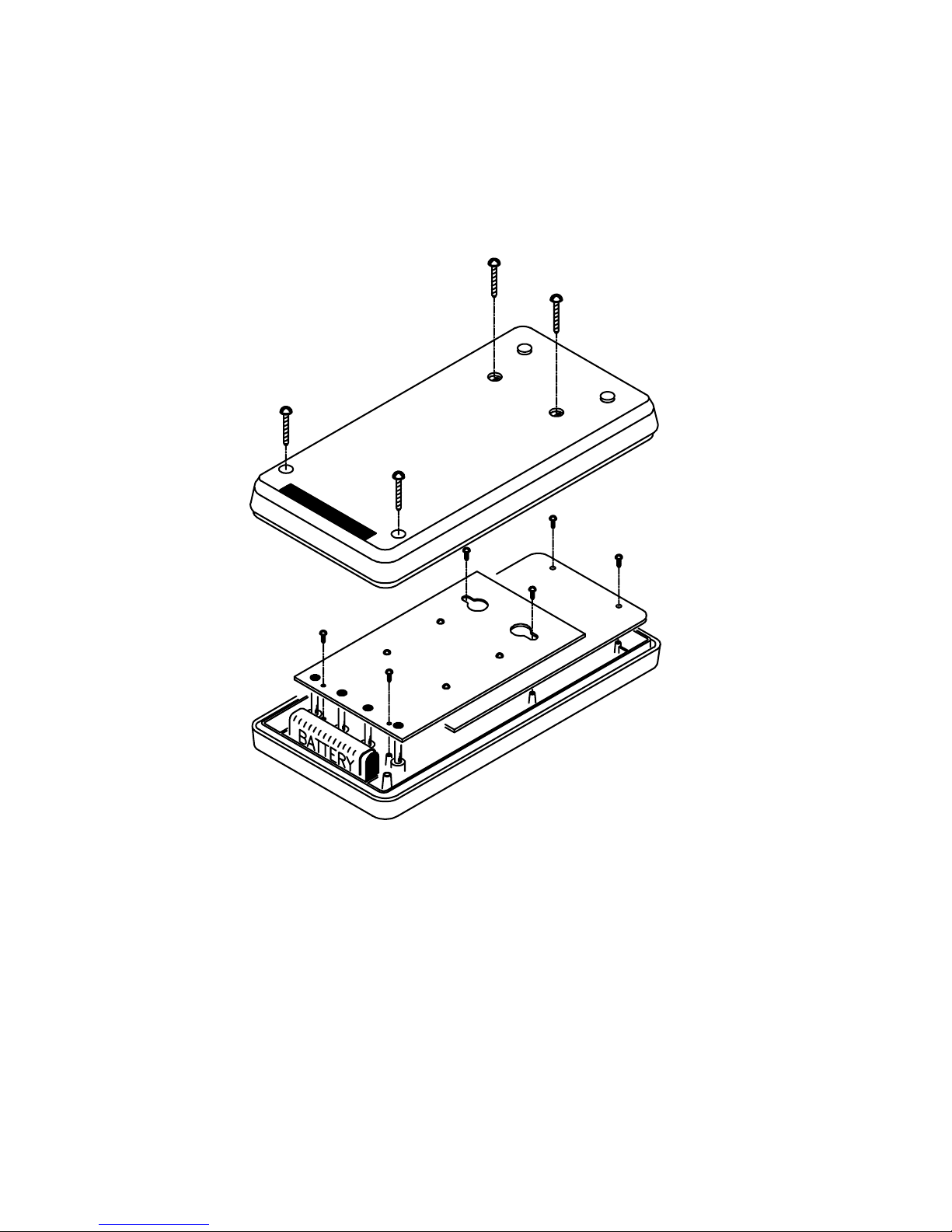
17
Fig-3

18
Fig-4
Table of contents
Other TES Multimeter manuals


