Table
of
Contents
Page
INtrOGUCTION.
0.2...
cece
ec
ceeeeeceeeeeeeeeeeeeeetaeeeeeeeeeeees
1
Safety:
INMOMMAVON
resccesssecwsseecworcserearerssessererseewes
1
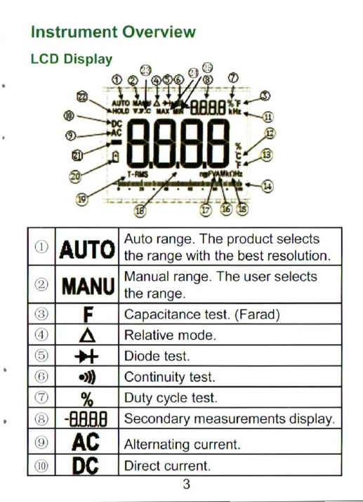
Instrument:
OVEWICW
isvesccesremmnreemscres
3
UCD"
Display
sxervcererrsst
tithe
3
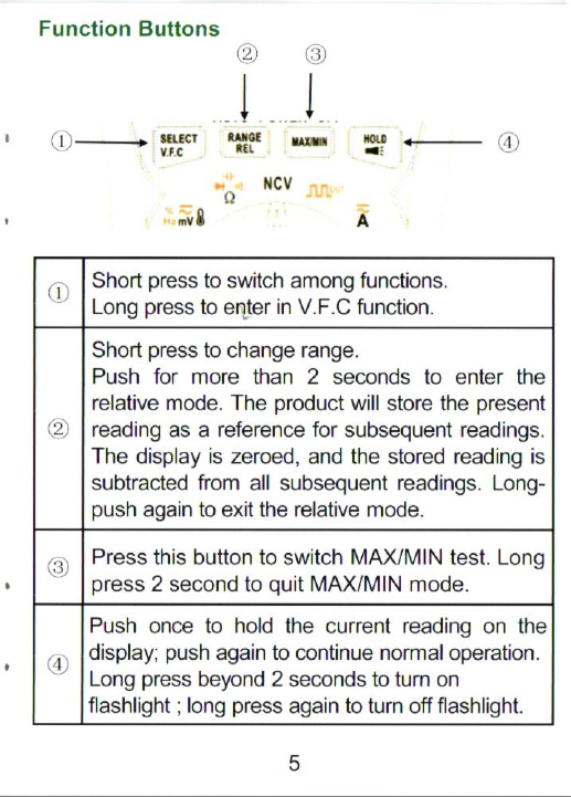
FUNCTION,
BULONS......::c.c0scsecceneecsssscsssesedsectens
5
Rotary:
BUUONS
tacts
ectutnniwn
eames
6
Input?
Term
ihalSseccssnversscsseseessreesnaeseseszersees
8
Measurements
Instruction......0.....ccceceeeeeeeeeeeeee
9
Measure
AC/DC
Voltage............ccccecceeeeteeeees
9
Measure
AC/DC
Current..............cccseceeseeeeeeee
9
Measure
Resistance
ieiccsssssesscerneraceccn:
10
Test
Diodes
and
Continuity............00.....000
10
Measure
Capacitance................cccccceceeeeeeees
11
Measure
Frequency
and
Duty
Cycle.............
12
Measure
Temperature.................:ccccccesseeeeeees
13
Test
NCV......
0...
cceccec
eee
e
cee
eseeeeeeeeneenes
13