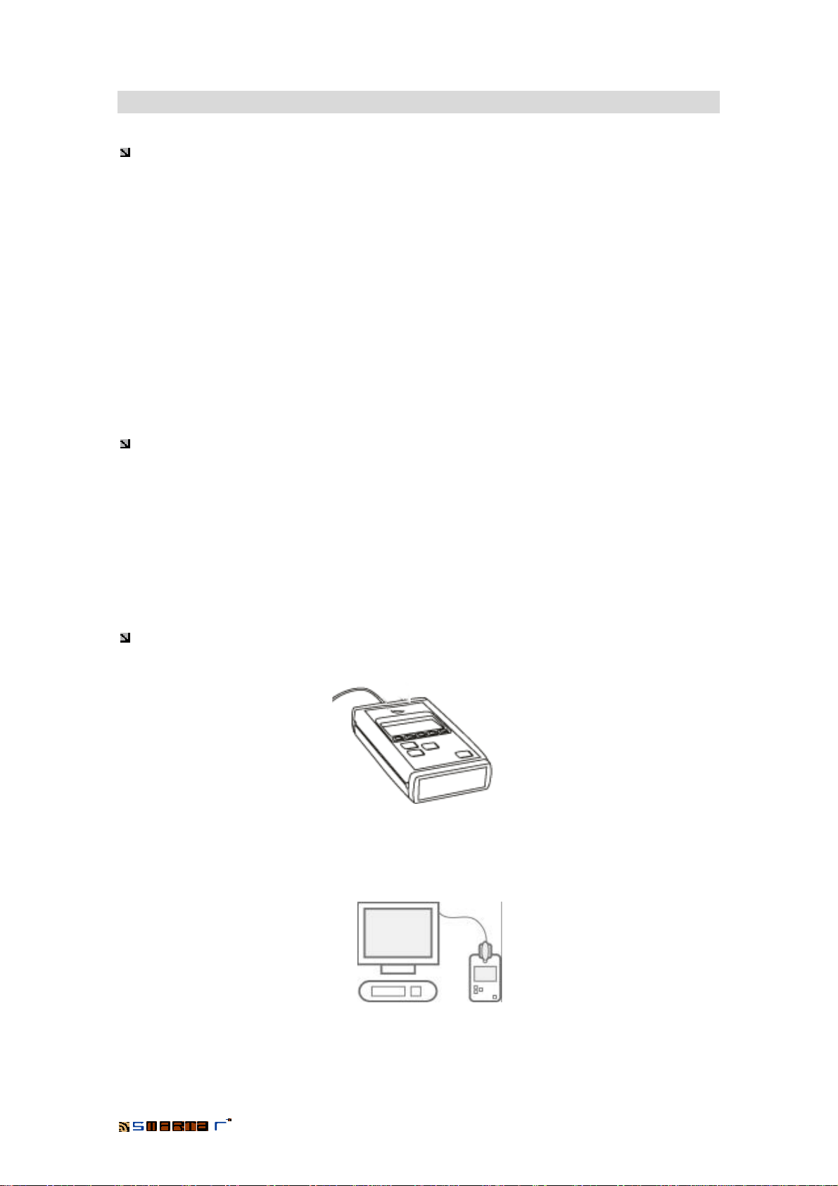
TESA smartair TS1000 User manual

TS1000 System/
Portable Programmer

PORTABLE PROGRAMMER
2
Index
1. INTRODUCTION…………………………………………………………………..3
2. TECHNICAL CHARACTERISTICS……………………………………………..4
2.1. General Aspects…………………………………………………………………………….4
2.2. Keyboard..................................................................................................................... 4
2.3. Power Supply………………………………………………………………………………..5
2.4. Connectors and CLR button………………………………………………………………5
2.5. Storage Capacity........................................................................................................7
3. PORTABLE PROGRAMMER: OPERATION………………………………….8
3.1. Transmission of Data to the Portable Programmer…………………………………..8
3.2. System Security. Authorisation Key…………………………………………………….9
3.3. Operations of the Portable Programmer………………………………………………..9
3.4. Menu of the Portable Programmer……………………………………………………..10
3.4.1. Switch on / off the light
3.4.2. Date and Time
3.4.3. Language
3.4.4. Automatic
3.4.5. Version
3.5. Doors Menu…………………………………………………………………………………13
3.5.1. Update
3.5.2. Initialise
3.5.3. Open
3.5.4. Test
3.5.5. On Line Address
3.6. Users Menu............................................................................................................... 18
3.6.1. Read Key
3.6.2. Test
3.7. Openings Menu…………………………………………………………………………… 20
3.7.1. Get Audit Trail
3.7.2. See Openings
3.7.3. Configure Openings
3.8. Installation Menu…………………………………………………………………………. 22
3.8.1. Select Site
3.8.2. Configure Site
4. MAINTENANCE OF THE PP: TEST………………………………………….24
4.1. Keyboard Test…………………………………………………………………………….. 24
4.2. Clock Test…………………………………………………………………………………. 26
4.3. Test of the Key Connector……………………………………………………………… 26
4.4. Test of the Cable with Key………………………………………………………………27
4.5. Memory Test…………………………………………………………………………….…27
5. KEY ENCODER: OPERATION………………………………………………..29

PORTABLE PROGRAMMER
3
1. Introduction
TESA Access Control is a system based mainly on products named off line. That means,
they are products that they run without a direct connection to a computer or a control unit that
governs them. See the range of products:
STX Series Electronic Cylinders Off Line
Electronic Keys Off Line
ST Series Electronic Locks Off Line
Wall Readers Off Line / On Line
IT Series Electronic Locks Off Line
Wall Readers Off Line / On Line
ITD Series Electronic Locks Off Line
Wall Readers Off Line / On Line
In the off line range of products, the control unit is one part more of the product and in the
case of the electronic locks, they are completely fed by standard batteries.
This control unit has memory and a real time clock. This allow us to obtain high access control
features.
The great advantage of the off line products, is that we can install them on any door, without
any wiring and without an expensive cost.
However, we need a device to transfer the information from the computer to the cylinder and/or
locks and vice versa.
This device is the Portable Programmer (PP):
Apart from being the connecting element between the computer and the different products, the
Portable Programmer, connected to the computer and managed from the TS1000 Management
Software, is the encoder of the user keys for the electronic cylinders (STX Series).

PORTABLE PROGRAMMER
4
2. Technical Characteristics
2.1 General Aspects
The general dimensions of the PPare 90x165x30mm:
2.2 Keyboard
The Portable Programmer has a membrane keyboard detailed below:
On / Off It switches the Portable Programmer on and off. The Portable
Programmer has also a timer to switch itself off if no key is pressed.
Enter Key to select and/or accept the different options in each menu of the
Portable Programmer.
CursorsKeys to select one option from the menus.
Function Keys F1, F2, F3, F4 and F5.To access the menus of the PP.
Screen Display with a resolution of 128x64 pixels.
Screen
Enter
F
unction Keys
Cursors
On/Off

PORTABLE PROGRAMMER
5
2.3 Power Supply
The Portable Programmer is fed by a 6LR61 type 9V DC alkaline battery.
The programmer switches itself off if it has not been used for 30 seconds, and this prevents us
from leaving the programmer on.
The memory of the Portable Programmer is volatile, and hence if we remove the battery or if the
battery runs down it will lose the information stored in it.
The battery is housed on the bottom base of the Portable Programmer. To extract it we must
remove the bottom lid of the Portable Programmer.
The Portable Programmer also indicates us the battery charge level.
In the top left corner of the main screen of the programmer there is an indicator of the charge
of the battery, as shown in the following illustration:
Besides, the Portable Programmer includes a connector to be fed through an external power
supply. Thus, when the Portable Programmer is being fed externally, it does not consume
battery.
This feature is useful to carry out different operations with the Portable Programmer in the
computer. Using only batteries to carry out operations on the door.
The consumption of the Portable Programmer, with the screen light switched off is 20mA either
in a stand-by state or communication state. If we switch on the light of the screen, the
consumption will increase in 10mA.
2.4. Connectors and CLR button
The Portable Programmer has the following connectors:
State of the charge
of the battery.
1
2
3
4
5
1
-
RS
-
232 connection to the computer.
2-Jack connection for the cylinders or locks.
3-CLR button.
4-Connection to modem.
5-Connection for the keys.

PORTABLE PROGRAMMER
6
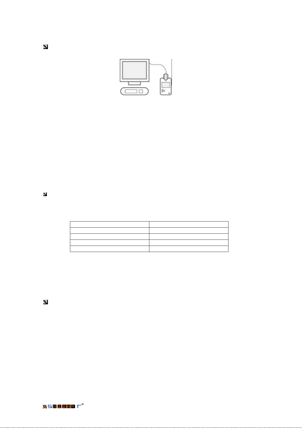
1-RS-232 connection to the computer
The Portable Programmer is connected to the computer by means of a RS-232 cable with two
connectors of 9 PINS. One is for the computer’s serial port and the other for the portable
programmer. Most of the times the port used by the computer will be the COM1 series port. This
will depend on the configuration of the computer and the serial port available for the connection.
From the TS1000 management software of the system we will select the serial port used by the
computer for the connection.
The RS-232 cable is supplied with the Portable Programmer.
2-Jack connection for the cylinders, locks or wall readers
To connect the Portable Programmer to the cylinders, locks and/or wall readers we use a
special cable. There are two different cables:
Connection cable for locks and/or wall readers: It is a cable with a “jack” type of connector
in both sides.
Connection cable for cylinders: The side of the cable which is used to connect with the
Portable Programmer is “jack” type, while the side to connect with the cylinders is an electronic
key.
(Both cables are supplied with the Portable Programmer)
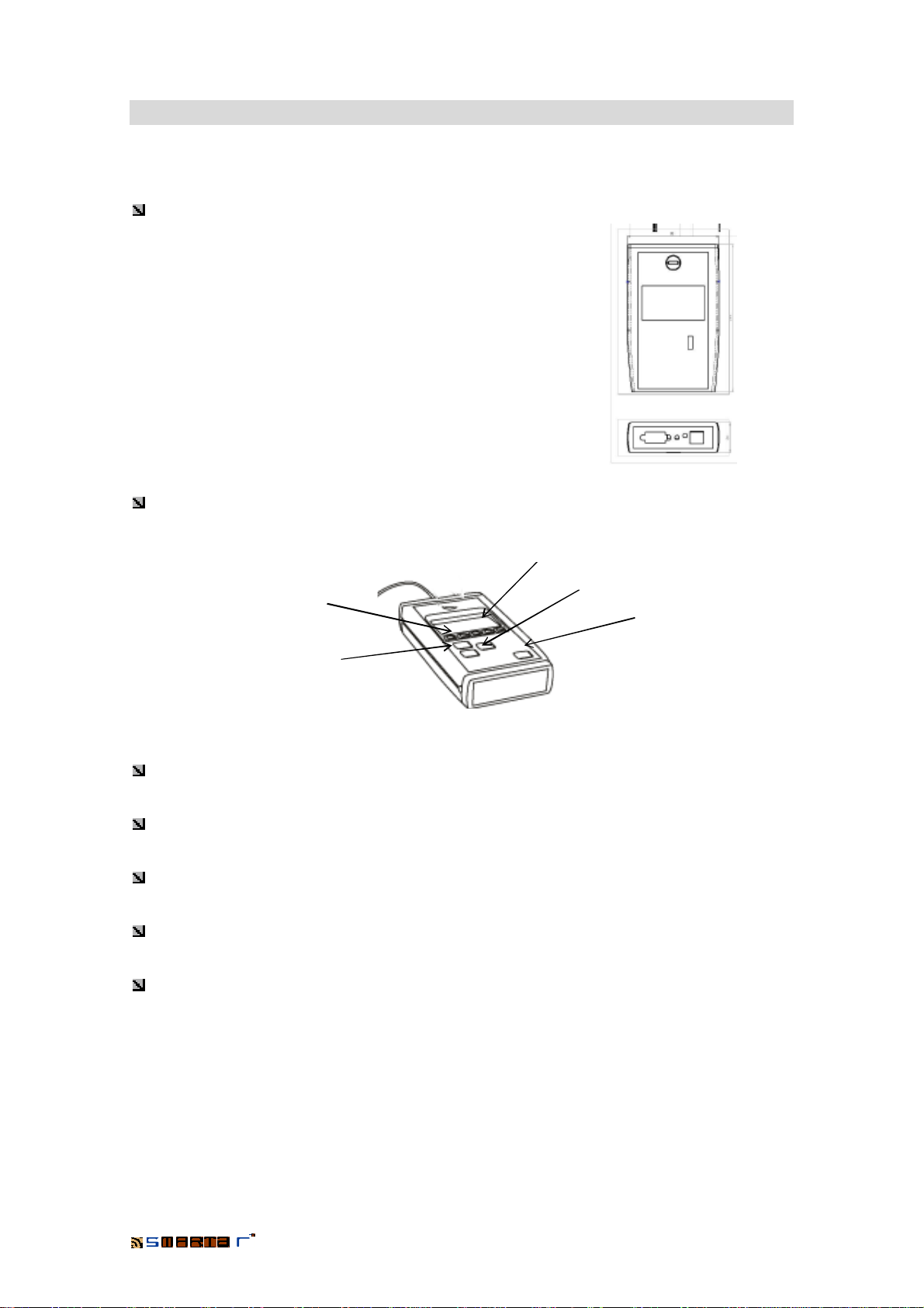
3-CLR button
It is used to reset the Portable Programmer and to test it. By means of the test we can check
the operation of the programmer.
(See chapter TEST OF THE PP: RESETTING THE PORTABLE PROGRAMMER of this
manual)
4-Connection to an external power supply
The Portable Programmer has a connector for an external power supply. When the Portable
Programmer is fed through this power supply, there is not any consumption of battery. This
option will allow us to use the batteries only in the operations that we carry out on the doors,
where is not possible to use an external power supply.

PORTABLE PROGRAMMER
7
5-Connection for the keys
It is a cylinder plug where the keys are inserted to be recorded or read.
2.5 Storage Capacity
The Portable Programmer has a memory of 0,5MB.
This is, however, a very relative data. The portable programmer receives information about the
doors forming part of a locking plan. That is, the users who will have access to them, the time
zones in which they will have access, the calendar of "public holidays" in the installation, etc.
Therefore the number of doors that we can transfer to the Portable Programmer will depend
above all on the number of users forming part of the installation.
The following table shows the number of doors to load on the Portable Programmer,
depending on the number of users per door:
Users/Doors Doors to load on the PP
50 Up to 1000 doors approx.
100 Up to 500 doors approx.
200 Up to 250 doors approx.
500 Up to 100 doors approx.
The number of events that we can register from the doors also depends on the number of
events that we have stored on them. The cylinders and/or locks can store up to 1,000 events
(when the number of users does not exceed 1,000).
If the doors have stored the maximum number of events, we can register the events of a
maximum of 50 doors in the Portable Programmer.

PORTABLE PROGRAMMER
8
3. Portable Programmer: Operation
We have mentioned that the Portable programmer is the link between the management
software of the system, which is installed on the computer, and the electronic cylinders, locks
and/or wall readers. With it we can transmit or receive information from the cylinders, locks or
wall readers, and carry out different tasks.
To transmit information to the cylinders or locks,the portable programmer must receive that
information from the computer. Therefore, the first thing to do is transmit the information of the
locking plan of the installation in question to the Portable Programmer. Once we have
transmitted the information we will be able to carry out the tasks which are described later on.
3.1 Transmission of data to the Portable Programmer
To transmit the locking plan of the installation to the PP we connect it to the computer with
the RS-232 cable and we switch it on by pressing the ON/OFF key.
From the PP screen of the TS1000 management software of the system we send the locking
plan by clicking on the button "Send Data to PP", as shown in the ensuing illustration:
When clicking on the button the software creates a data file which is sent to the Portable
Programmer. The transmission time will depend on the amount of information we are sending.
Send Data to PP

PORTABLE PROGRAMMER
9
Once we have finished with this task, the window will display a message indicating that the
information has been transmitted correctly.
Once the data of the locking plan has been transmitted to the Portable Programmer we can
transfer that information to the cylinders, locks and/or wall readers and do the operations that
we will explain later on.
3.2 System Security -Authorisation Key
For security reasons, the Authorisation Key will have to be inserted on the Portable
Programmer when carrying out the operations Initialise, Update and Open (which are described
later) in the cylinders, locks and/or wall readers with the Portable Programmer. Otherwise we
will not be able to carry out any operation.
We must remember that the Authorisation Key guarantees the security of the installation, and
that there is only one key for each installation.
(For more information see the Software Manual. TS1000 System)
3.3 Operations of the Portable Programmer
The main screen of the Portable Programmer is shown in the following illustration:
Authorisation key

PORTABLE PROGRAMMER
10
By means of the F1, F2, F3, F4 and F5 function keys we can access the different menus of the
Portable Programmer.
The menus are:
F1 Portable Programmer
F2 Doors
F3 Users
F4 Register of openings
F5 Installation
3.4 Menu of the Portable Programmer
By pressing the F1 key we access the menu of the Portable Programmer. The functions
inside that menu are the following:
With the Up and Down cursor keys we can select the different options. Once the desired option
has been selected we access the option by pressing ENTER.
3.4.1 Switch on / off the light
This option allows us to switch on/off the light of the screen. It is useful to avoid unnecessary
consumption, therefore we will only use the light on the screen in situations or places with very
low visibility.
As we has already mentioned before, the consumption of the Portable Programmer is 20mA
with the light of the screen switched off and 30mA with the light of the screen switched on.
By default, when the Portable Programmer does not have any data from the locking plan, the
light will be switched off.
As well, the light will be switched off when the data of the locking plan is transmitted, by default.
To switch on the light, we need only to press “Enter” with the selected function.
If we press “Enter” in this position, the light will switch on and the Portable Programmer will
come back to the main screen.
Switch on / off the light
Data and Time
Language
Automatic
Version

PORTABLE PROGRAMMER
11
The next time we press the F1 function key, we will see the following illustration:
If we press “Enter” in this position, the light of the screen will switch off.
3.4.2 Date and Time
After selecting the option Date and Time, we press ENTER to access that function.
Thus we display the date and the time of the clock of the portable programmer. We cannot
modify it, because the programmer takes the computer’s date and time. When we send the
information of the locking plan from the computer to the portable programmer the date and time
of the computer are also transmitted.
Therefore, in order to modify the date and time of the portable programmer we must first modify
the time on the computer and then re-send the data to the portable programmer. This way,the
programmer will take the new date and time.
Press ý(F5) to accept and go back to the main screen of the Portable Programmer.
3.4.3 Language
By choosing Language in the configuration menu with the Up or Down cursor keys and
pressing ENTER we access the Language option of the portable programmer.
On that function we can display the language being used by the portable programmer. As the
Date and Time, the Programmer takes the Language from the computer that is transmitting the
data.
To accept and go back to the main menu of the Portable Programmer, press ý(F5).

PORTABLE PROGRAMMER
12
3.4.4 Automatic
The programmer offers us the possibility to Update doors (cylinders, locks and/or wall readers)
and Pick Up Openings automatically. This means that, when we connect the Portable
Programmer to the door, the PP will automatically send information (if there is any modification
in the locking plan of that door) and show the register of openings without having to do any
operation in the programmer.
In order to access the Automatic function, we select that function with the Up or Down cursor
keys on the configuration menu and then press ENTER.
The programmer will ask the following question: “Do you want to update doors
automatically?”
To answer yes, press þ(F4), and to answer no, press ý(F5).
Once we have chosen the option above (Update), the Portable Programmer will ask us
whether we want to Pick Up the Openings automatically: “Do you want get the audit trail
automatically?”
As in the previous option, to answer yes, press þ(F4) and to answer no, press ý(F5).
Once we have selected the option above we go back to the main screen of the Portable
Programmer.
If the answer to the automatic updating has been positive the symbol of the doors will be
displayed on the top right corner of the main screen, and if it is negative the symbol will not be
displayed.
Updating of Doors and
Automatic Pick-up of
openings.

PORTABLE PROGRAMMER
13
3.4.5 Version
By selecting the Version function of the configuration menu with the Up or Down cursor keys
and pressing ENTER, the portable programmer shows us its manufacture version.
To accept, we press ý(F5) and we go back to the main screen of the Portable Programmer.
3.5 Doors Menu
By pressing F2 on the main screen of the Portable Programmer we access the Doors menu.
This menu includes the ensuing operations:
Update
Initialise
Open
Test
On Line Address
To carry out the functions Update, Initialise and Open successfully the Authorisation Key of
the installation must be inserted on the Portable Programmer.
If we try to do any of these operations without inserting the Authorisation Key on the PP we
will see an Error message such as the one in the following illustration:
3.5.1 Update
The Update function is used when we need to transfer changes made in the locking plan of a
door to a cylinder, lock or wall reader. That is, it is a cylinder or lock that has already been
"initialised" and therefore belongs to the installation.
Once we have made the necessary changes in the TS1000 management software,we send
the data to the portable programmer. From there they are transmitted to the cylinder or lock by
means of the Update function.

PORTABLE PROGRAMMER
14
With the authorisation key inserted on the Portable Programmer and the programmer
connected to the door, we press “Enter” to carry out the Updating.
As the cylinders, locks or wall readers have already been initialised and therefore registered
in the installation, the Portable Programmer will recognise which door it is and immediately
update it. The screen of the programmer will be:
Once the Portable Programmer finishes the operation we see the following screen:
We press ý(F5), to accept and go back to the main menu of the Portable Programmer.
3.5.2 Initialise
Initialising a cylinder, a lock or a wall reader consists in assigning that cylinder, lock or wall
reader to a door of the installation and transmitting it all the information concerning its locking
plan.
When a product is initialised,it loses all the information it may have stored. If it is a cylinder, lock
or wall reader in the initial state, it will then become part of the installation.
When a cylinder, lock or wall reader starts to form part of an installation, it can only be initialised
again with the information of another door from the same installation. That is, once initialised we
can move them from one door to another as many times as we wish, but these doors will have
to belong to the installation for which they were initialised.
We select the "Initialise" function of the Doors menu and press ENTER. Then we will see a
screen like the following:
LOCK CYLINDER

PORTABLE PROGRAMMER
15
That is, we arrive at a screen that shows a list of all the doors of the installation. With the Up
and Down cursor keys we select the door that we want to initialise and with the authorisation
key inserted on the PP we press ENTER to start initialising.
Once this is done, we obtain a message telling us that the operation has been carried out
successfully.
We press ý(F5) to accept and go back to the main menu of the Portable Programmer.
3.5.3 Open
With the Open function we can open cylinders, locks and wall readers in an emergency.
With the Up and Down cursor keys we select the Open function in the Doors menu of the
portable programmer. We press “Enter” and the Portable Programmer opens the door. (It is not
need to say that the Authorisation Key must be inserted in the Portable Programmer)
Once this is done we obtain a warning message telling us that the door has been opened in
an emergency. The cylinder, lock or wall reader remains open for a few seconds while we carry
out the operation we should carry out. A few seconds later the cylinder, lock or wall reader
closes.

PORTABLE PROGRAMMER
16
3.5.4 Test
With the test function of the portable programmer we can check the cylinder, lock or wall reader.
On the Doors menu of the portable programmer we select Test with the Up and Down cursor
keys. With Test selected we press “Enter” and start the test.
In the case of the cylinder, the first thing that the portable programmer does is read the version
of the cylinder. Of course, the portable programmer must be connected to the cylinder by
means of the connection cable for the cylinder.
We can see it in the following screen:
For locks, besides the lock version, we will check the clock, the privacy lever, the keyboard (if
the lock has one) and the warning LED.
The process is as follows:
From the Doors menu and with the Test option selected we press ENTER. The Portable
Programmer will indicate the type of lock, as in the following illustration:
Pressing “Enter” again the Portable Programmer will indicate the date and time of the lock. It
will also show the name of the door with which the lock has been initialised:

PORTABLE PROGRAMMER
17
Then we do the reader test and the test of the crutch key of the security lever. The portable
programmer will ask us whether we want to do that test:
To accept we press þ(F4) or to not accept we press ý(F5) and we will go to the next test. If
we do the test, we will see a screen as the following:
The test of the crutch key of the lever (or privacy) is carried out by turning it 90º. The security
lever will come out (this means that the lever is on the door). If it works properly, we will see a
circle to the left of the text "Privacy" and the text will darken.
We press “Enter” and we check the keyboard of the
lock. If the lock does not have a keyboard, the Portable Programmer recognises it and displays
a message like the following:
If the lock has a keyboard, we will press all the keys of the lock one by one to check that they
work properly.
The last step is the test of the warning LED. The Portable Programmer will ask us whether
both LED (the green one and the red one) are on.

PORTABLE PROGRAMMER
18
If the answer is yes we press ENTER to end the test.
3.5.5 On Line Address
The installation of the On Line wall readers consist of two steps:
•Initialisation The initialisation of the on line wall readers is exactly the same
as the cylinders, locks and/or off line wall readers. Process
already describe in this manual.
•On Line Address The on line wall readers are connected to the computer where
the TS1000 management software is running through the Unit
Area. Each Unit Area can govern until 30 on line wall readers.
The On Line Address consists on assigning one of the 30
addresses on the Unit Area.
If we press the “Enter” button with the “On Line Address” option selected, we see the
following screen:
With the cursors we select the wished address and press the “Enter” button. We will receive a
message confirming the executed On Line Address.
3.6 User Menu
In the User menu we can read the electronic keys without having to be connected to the
computer and without needing to test the key.

PORTABLE PROGRAMMER
19
To do this we press the User icon (F3 function key) on the main screen of the Portable
Programmer. We will then see a screen such as the following
3.6.1 Read key
We insert a key on the plug of the Portable Programmer and press “Enter” to start reading the
key. The information of the key will be displayed:
That is, we collect all the information of the key: User name whom belong, activation and
expiration dates, emission date of the key and key state (authorisation key, expired key, old key,
etc.).
We press ý(F5), to accept and go back to the screen of the Portable Programmer.
To be able to read the information of the key, the locking plan of the installation must be loaded
and selected on the portable programmer.
If the key does not belong to any locking plan loaded at that moment on the portable
programmer, we will get an error message like the following.
3.6.2 Test
Through the key test we will be able to know its version, date and clock time and we will test the
operation of the warning LED.
With a key inserted in the Portable Programmer, we press “Enter”. The first information we get
is the key version, as we see in the following illustration:

PORTABLE PROGRAMMER
20
We press “Enter” and we check the clock. We will get the current date and time of the key
clock.
We press “Enter” to follow with the Test. If the Portable Programmer detects a gap between
the key date and time and the Portable Programmer, it will ask us if we want to update the key
clock.
Pressing “Enter” we will proceed to update the date and time of the key clock.
Pressing the “Enter” button we follow with the Test. The next step is to verify the operation of
the warning LED of the key.
We press the “Enter” button to finish the key Test. The Portable Programmer will go back to
the main menu.
3.7 Opening Menu
The Openings menu shows the register of events stored in the cylinders, locks and/or wall
readers.
From the main screen of the portable programmer we press the F4 function key (which is
linked to the register of openings). Then we will see the following menu of options:
Table of contents