Teseq INA 703 User manual

1
INA 703
MAgNetIc fIeld coIl
User MANUAl
601-335A
Advanced Test Equipment Rentals
www.atecorp.com 800-404-ATEC (2832)
®
E
s
t
a
b
l
i
s
h
e
d
1
9
8
1

INA 703 Magnetic field coil
INA 703
MAgNetIc fIeld coIl
User MANUAl

1 Explanation of symbols 5
2 Introduction 6
2.1 General description 6
2.2 Supply frequency magnetic elds 7
2.3 Pulsed magnetic elds 8
2.4 Oscillatory magnetic elds 9
3 User instructions 10
3.1 General 10
3.2 Unpacking and installation 10
3.3 Positioning 13
3.4 Connection to the generator 14
3.4.1 Connecting to Teseq ProfLine system for IEC 61000-4-8 testing 15
3.4.2 Connecting to Teseq MFO 6501 or MFO 6502 for IEC 61000-4-8
testing 15
3.4.3 Connecting to any other generator for IEC 61000-4-8 testing 16
3.4.4 Connecting to Teseq NSG 3040 or NSG 3060 for IEC 61000-4-9
testing 17
3.4.5 Connecting to Teseq NSG 3040 or NSG 3060 for IEC 61000-4-10
testing 17
3.5 Test execution 17
4 Maintenance and function check 19
4.1 General 19
4.2 Cleaning 19
4.3 Function check 19
4.4 Calibration 20
4.5 Warranty 20
5 Declaration of conformity (CE) 21
6 Options and accessories 22
6.1 INA 703 Stand 22
6.2 INA 703 Coil 22
6.3 INA 3250 interconnection cable 23
6.4 INA 3251 Interconnection cable 23
6.5 Pulse wave shape adapter INA 752 23
6.6 MD 300 surge pulse current probe set 24
7 System description 25
8 Addresses 26
coNteNts

Lethal danger from high voltages and the risk of radiat-
ing illegal electromagnetic interference.
This system must be used only for EMC test purposes
as specied in these operating instructions.
The INA 703 must be installed and used only by autho-
rized and trained EMC specialists.
Personnel tted with a heart pacemaker may not
operate the instrument and must not be in the vicinity
of the test setup while it is in operation.
When the system is used in conjunction with options,
accessories or other equipment the safety instructions
concerning those devices must also be observed.

5
1 explANAtIoN of syMbols
Please take note of the following explanations of the symbols used in order
to achieve the optimum benet from this manual and to ensure safety during
operation of the equipment.
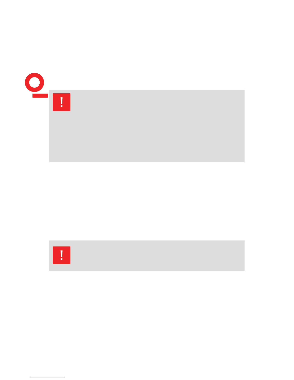
The following symbol draws your attention to a circumstance where non-
observation of the warning could lead to inconvenience or impairment in the
performance.
Example:
This connection must not be confused with the Equip-
ment under Test (EUT) power input.
The following symbol draws your attention to a circumstance where non-
observation of the warning could lead to component damage or danger to the
operating personnel.
Example:
Never connect or disconnect the EUT while the test
system is performing a test.
6
INA 703 Magnetic field coil
INA 703 is the top end of a family of magnetic eld coils, designed for testing per
IEC 61000-4-8 (supply frequency magnetic elds) , IEC 61000-4-9 (pulsed magnetic
elds), IEC 61000-4-10 (oscillatory magnetic elds).
Thanks to a multi wire - 37 turns – concept , it allows the generation of elds higher
than 1000 A /m while using a current source rated for 30 A, so insures the possibility
to meet the IEC 61000-4-8 standards requirement of a current THD < 8% which can
be met only when using a synthetic current source.
INA 703 has a connection possibility after wire turn 1 and turn 5, which allows to
reach great accuracy when generating low amplitude elds.
2 INtrodUctIoN
2.1 General description

7The tap off after 1 turn is also used for tests per IEC 61000-4-9 and IEC 61000-4-10,
which both require a single turn coil.
For tests per IEC 61000-4-8, INA 703 can be used as an accessory to the Teseq
proine system, together with a NSG 1007- 5 kVA source, the INA 2141 impedance
box and the WIN 2120 software can generate supply frequency elds (50 and
60 Hz) up to 330 A/m continuously and 1100 A/m short term (3 s).
It can also be used with the MFO 6501 or 6502 current sources and the NSG 3000
series of generators and generate Supply frequency elds (50 and 60 Hz) up to
120 A/m continuously and 120 A/m short term (3 s).
For tests per IEC 61000-4-9, INA 703 can be used together with a classic combined
wave generator as available in NSG 3040 or NSG 3060 series plus a pulse wave
shape adaptor box INA 752.
For tests per IEC 61000-4-10, INA 703 can be connected to an adequate slow oscil-
latory waves generator.
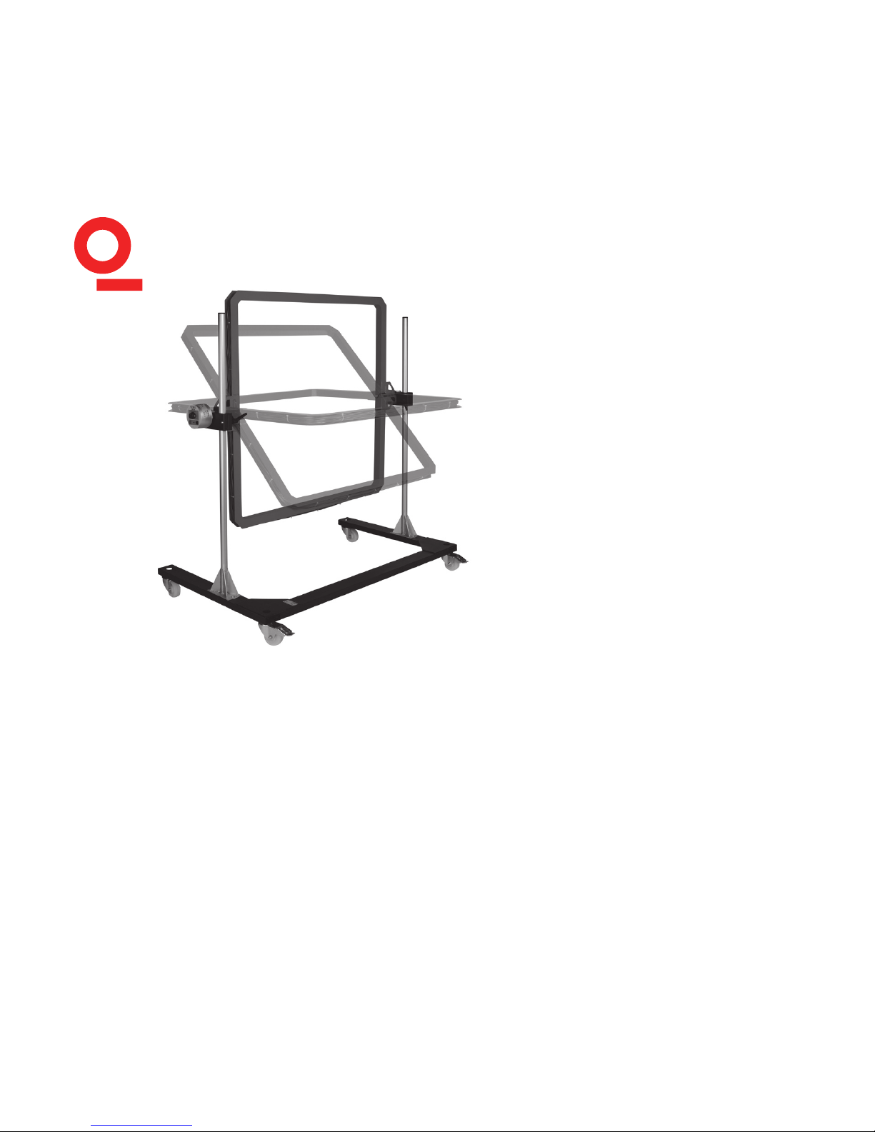
Thanks to the multi wire concept and to the professional mechanical design, like U
shape base on rolls which allows convenient approach and positioning to the test
table, INA 703 is the ideal accessory for magnetic eld testing.
2.2 Supply frequency magnetic elds
Supply frequency magnetic eld tests, simulate the magnetic elds typically gener-
ated by the current ow in power supply cables as specied in IEC/EN 61000-4-8.
Such magnetic elds can affect the operation of items of equipment that are sensi-
tive to them.
For testing to IEC 61000-4-8, the INA 703 needs to be supplied by a regulated 50 or
60 Hz current (THD<8%) of maximum 10 A continuously and 35 A short term (<5 s).
Single turn, 5 turns , and 37 turns can be selected in order to reach high elds with
low currents, but maintaining good resolution for lower elds testing.

8
INA 703 Magnetic field coil
2.3 Pulsed magnetic eld
The Teseq ProfLine system comprising an NSG 1007- 5 kVA source, an INA 2141
impedance box and WIN 2120 software is ideally suited for this application. For this
setup the interconnection cable INA 3250 is required.
The system can generate supply frequency elds (50 and 60 Hz) up to 330 A/m
continuously and 1100 A/m short term (3 s).
For more information please consult ProLne 2100 series user documentation.
The INA 703 can also be used with the Teseq MFO 6501 or 6502 current sources
and the NSG 3000 series of generators to generate supply frequency elds (50 and
60 Hz) up to 120 A/m continuously and 120 A/m short term (3 s). For this setup the
interconnection cable INA 3251 is required.
For more information please consult MFO 6501/2 or NSG 3040 series user manuals.
Pulsed magnetic elds tests, simulate the type of interference produced by surge
pulses as a result of lightning strikes to buildings or other metallic structures such
as free standing masts, ground conductors, grounding networks, etc. as specied
in IEC/EN 61000-4-9. Magnetic elds of this type can upset the operation of instal-
lations that nd themselves within such elds.
For testing to IEC 61000-4-9, the INA 703 can be used together with a classic com-
bination wave generator such as the NSG 3040 or NSG 3060 series.
For this test a single loop ( 1 turn) will be used.
In order to meet the pulse waveform required by IEC 61000-4-9, the waveshape
adapter INA 752 needs to be used.

92.4 Oscillatory magnetic elds
Oscillatory magnetic elds tests, simulate the type of interference produced by the
switching of medium and high voltage switchgears, as specied in IEC/EN 61000-
4-10.
Magnetic elds of this type can upset the operation of installations that nd them-
selves within such elds.
For testing to IEC 61000-4-10, the INA 703 can be connected to an appropriate slow
oscillatory wave generator.
For this test a single loop (1 turn) will be used.
10
INA 703 Magnetic field coil
3 User INstrUctIoNs
The INA 703 together with the adequate generator must be operated only by
authorized and trained specialists. The generator with the coil is to be used only
for the purpose specied by the manufacturer. The user is directly responsible for
ensuring that the test setup does not cause excessive radiated interference which
could affect other instrumentation or human beings. The test system itself does
produce EM radiation up to 1100 A/m .
3.1 General
3.2 Unpacking and installation
Check the packaging for signs of damage in transit. Any damage should be reported
immediately to the transportation company.
WARNING - Personnel tted with a heart pacemaker must
neither operate the instrument nor approach the test
setup while a test is being executed.
Only approved accessories, connectors, adapters, etc. are to be used to ensure
safe operation.
WARNING - Improper or careless operation can be fatal!
These operating instructions form an essential part of the equip-
ment and must be available to the operator at all times. The user
must obey all safety instructions and warnings.
Neither Teseq AG, Luterbach, Switzerland, nor any of its subsidiary
sales organisations can accept any liability for personal, mate-
rial or consequential injury, loss or damage that may result from
improper use of equipment and accessories.

11INA 703 is delivered dismantled, safely packed in a solid wooden box.
Identify the upper side of the box and remove cover after having removed the
screws.
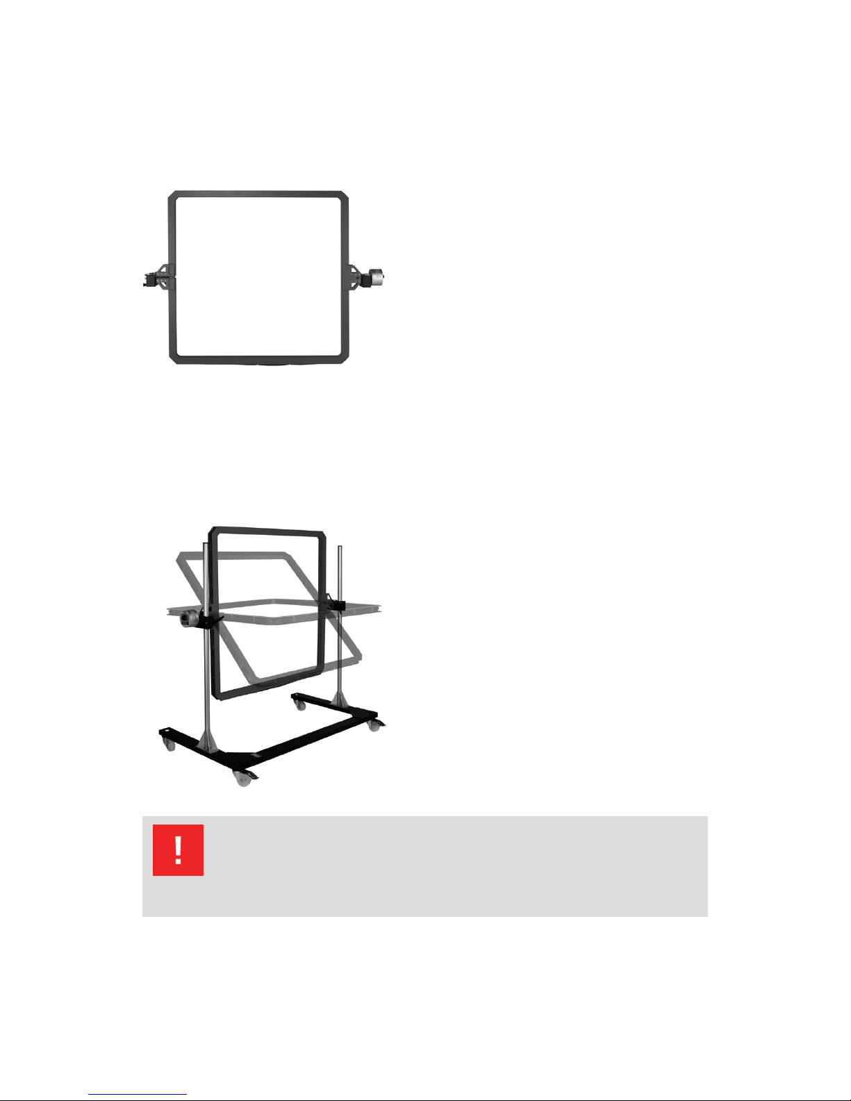
The contents of the package will look like:
Unpack carefully the various parts. Check the parts for signs of transport damage.
Any damage should be reported to the transportation company immediately.
Screw the vertical bars to the rolling base.
12
INA 703 Magnetic field coil
Lift (2 persons) the coil (red part) over the base, slide the black xtures into the
vertical bars.
Secure the coil by fastening the xtures to the bar.
The INA 703 is now ready to be rolled around to the test setup.
NOTE! Do not dispose of packaging materials. All packag-
ing should be retained in the event that the instrument
or any of its accessories should need to be returned to a
Teseq service center for repair or calibration.
133.3 Positioning
The U-shaped base with castors will allow easy positioning of the INA 703 to the
EUT, even if this one is placed on a test table.
The equipment to be tested shall always be positioned in the geometric center of
the red coil part
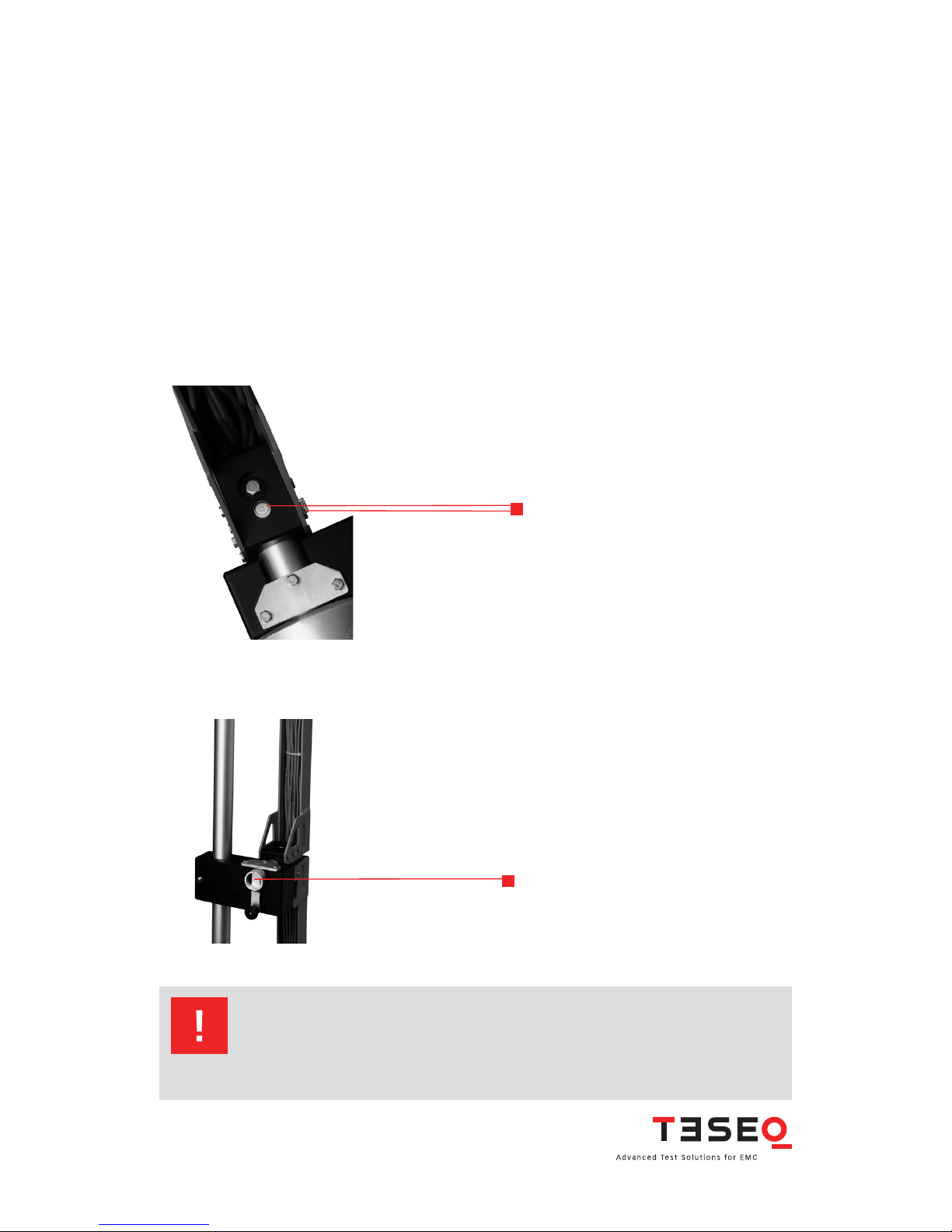
Tests need to be done with the coil in horizontal position and then in vertical posi-
tion, 2 bubble level indicators as shown in picture below will facilitate the right
positioning.
Bubble level indicators
Securing in horizontal and vertical position goes easy thank to the positioning lock:
Position lock
NOTE! Standards require only testing for horizontal or ver-
tical position. INA 703 positioning lock has an intermedi-
ate position at 45 ° which may be used for investigation
purposes.
14
INA 703 Magnetic field coil
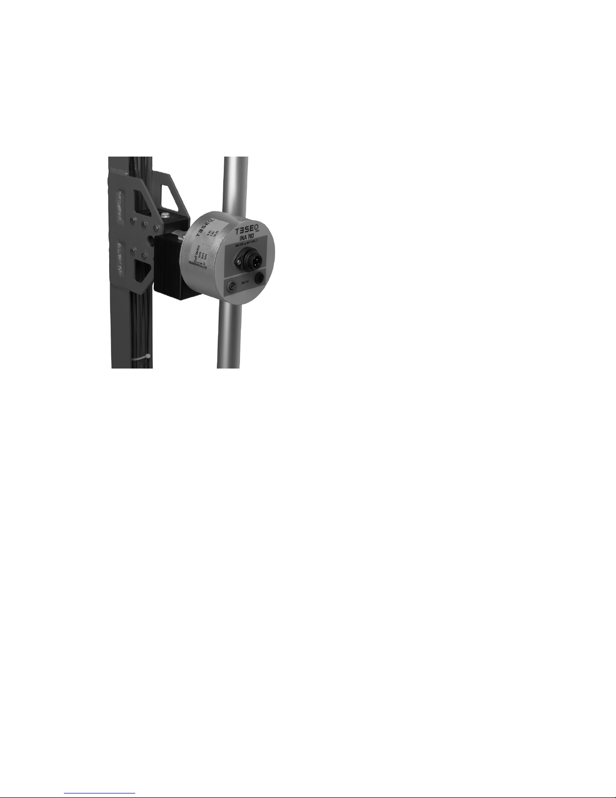
3.4 Connection to the generator
The INA 703 features a multipole terminal system which insures comfortable and
safe connection of various generators suited for various applications
Safety banana plugs: Red and black
These 2 plugs are mainly used for pulsed and oscillatory magnetic elds testing. The
Black banana is the low entry of the coil, the red banana is connected to the end of
Turn Nr 1. connecting to these terminals is equivalent to test with a single turn coil.
Round 4 pole connector:
The pole marked with PE sign is connected together with the black banana to the
low entry of the coil.
Pole Nr. 1 is connected together with the red banana to the end of turn Nr. 1
Pole Nr. 2 is connected to the end of turn Nr. 5
Pole Nr. 3 is connected to the end of turn Nr. 37
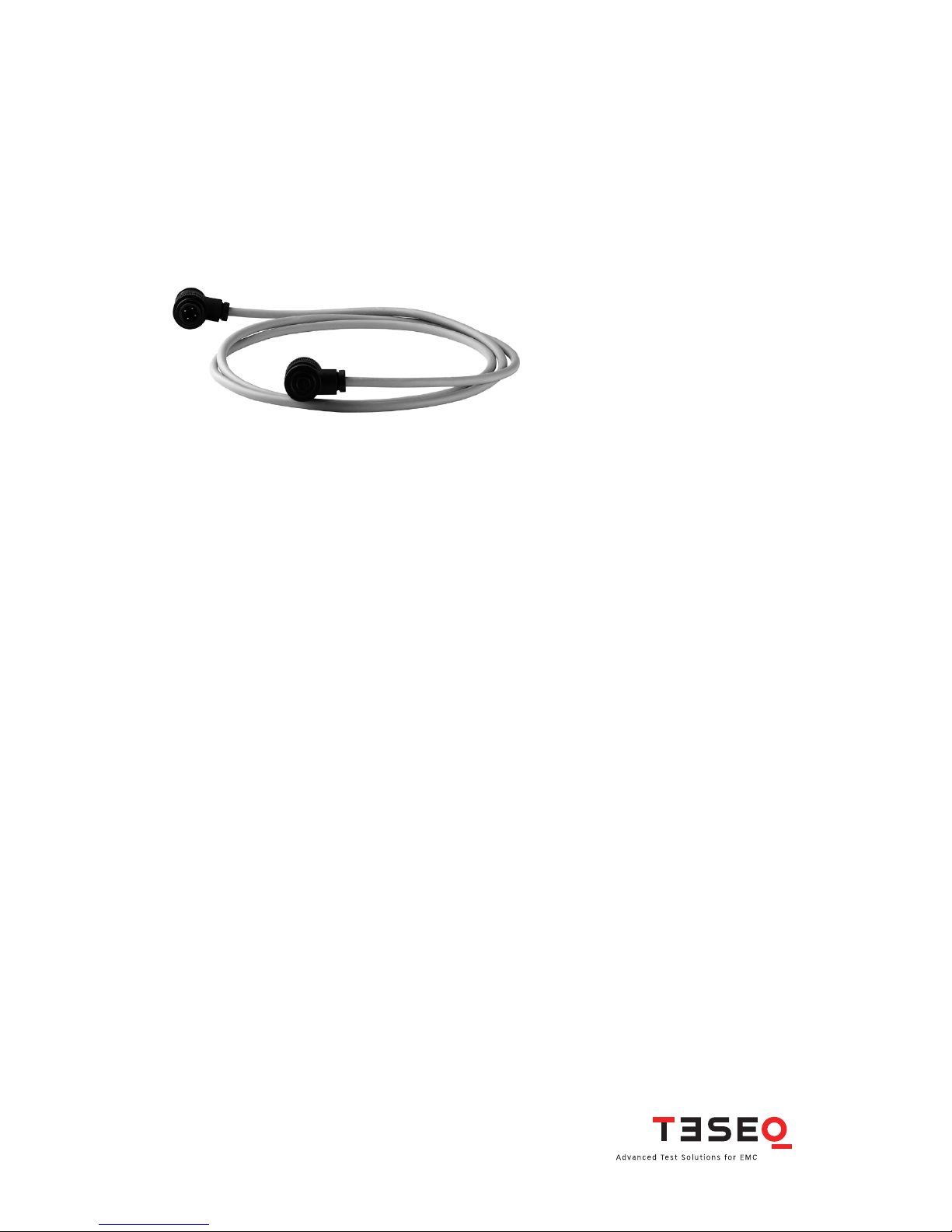
153.4.1 Connecting to Teseq ProfLine system for IEC 61000-4-8 testing
An INA 3250 interconnection cable is required. Connect the INA 3250 intercon-
nection cable directly from the 4 pole connector of INA 703 to INA 2141 of ProfLine
system.
The setting of the various levels and frequencies of supply frequency magnetic
elds is supported comfortably by the WIN 2120 software.
INA 2141 features 3 ranges (red selector on INA 2141 front: Position 0= Off, position
1 = 1 turn, position 2= 5 turns, position 3 = 37 turns) for better accuracy of low level
magnetic elds.
For each of the 3 ranges a separate coil factor (the coil factor is available in the
INA 703 calibration certicate and is also labelled on INA 703 terminal unit) needs
to be used. In the WIN 2120 software conguration le the INA 703 needs to be
congured as 3 separate coils.
For more information please consult the ProfLine systems user documentation.
3.4.2 Connecting to Teseq MFO 6501 or MFO 6502 for IEC 61000-4-8
testing
An INA 3251 interconnection cable is required. Connect the INA 3251 interconnec-
tion cable directly from the 4 pole connector of INA 703 to the output of MFO 6501.

16
INA 703 Magnetic field coil
The 3 ranges of the INA 703 are selectable by a respective banana plug (Green/
yellow = Low, blue = 1 Turn, Black = 5 Turns, red = 37 Turns) for better accuracy of
low level magnetic elds.
For each of the 3 ranges a separate coil factor. (The coil factor is available in the
INA 703 calibration certicate and is also labelled on INA 703 terminal unit) needs
to be used.
For more information please consult the NSG 3040 systems or MFO 6501/2 user
documentation.
3.4.3 Connecting to any other generator for IEC 61000-4-8 testing
An INA 3251 interconnection cable is required. Connect the INA 3251 intercon-
nection cable directly from the 4 pole connector of INA 703 to the output of the
generator.
The 3 ranges of the INA 703 are selectable by a respective banana plug (Green/
yellow = Low, blue = 1 Turn, Black = 5 Turns, red = 37 Turns) for better accuracy of
low level magnetic elds.
For each of the 3 ranges a separate coil factor. (The coil factor is available in the
INA 703 calibration certicate and is also labelled on INA 703 terminal unit) needs
to be used.
Make sure that the maximum ratings of INA 703 are not
exceeded – risk of re.
For Standard compliance testing the generator shall have
a THD<8%, this is not permanently guaranteed when
solutions based on variacs and step down transformers
powered from mains supply are used.

173.4.4 Connecting to Teseq NSG 3040 or NSG 3060 for IEC 61000-4-9
testing
The INA 752 pulse wave shape adapter is required.
INA 752 has at one end the right plugs tting into the surge out terminals of NSG
3040 and 3060 series, and at the other end the right safety banana plugs to t in
the INA 703 terminals.
For more information please consult the NSG 3040 or NSG 3060 systems user
documentation, section about magnetic elds testing
3.4.5 Connecting to Teseq NSG 3040 or NSG 3060 for IEC 61000-4-10
testing
The required connection cable is delivered together with the NSG 3040- MOW
generator series.
For more information please consult the NSG 3040 or NSG 3060 systems user
documentation, section about magnetic elds testing.
3.5 Test execution
The user must observe safety instruction for all the instruments and associated
equipment involved in the test setup.
Test setup conguration is to be strictly in compliance with the methods described
in the relevant standard to ensure that the test is executed in a compliant manner

18
INA 703 Magnetic field coil
WARNING - Users must be aware of the following dangers
that can occur during testing:
It is recommended for the user to stay away (at least a few meters)
from the loop antenna while magnetic elds are generated. Also
keep away magnetic eld sensitive devices and items such as
credit cards – magnetic key cards etc… which might be inu-
encedby the elds.
The eld generated in the loop antenna is directly proportional to
the current owing through it:
Field strength (A/m) H = Cf x I
Where H is the generated eld, Cf the coil factor, I the current
owing through the loop.
The use and setting of the generator and associated software is
given in the generator user documentation.
19
Maintenance by the user is restricted to visual inspection, cleaning the outer
housing, performing a function check and verication of the pulse parameters.
4 MAINteNANce ANd fUNctIoN
check
4.1 General
4.2 Cleaning
In general a moist cloth is sufcient for cleaning the outer housingl. If necessary
add a small amount of a mild, non-foaming household cleanser.
No chemicals (acid, etc) should be used for cleaning purposes.
Before beginning to clean the test system ensure that it is switched off and the
mains power cable is unplugged from the supply.
4.3 Function check
Functional check of the whole system (generator plus INA 703) can be made by
monitoring the current owing through the INA 703.
This current, multiplied by the coil factor, will give the generated magnetic eld.
Supply frequency current may be measured by a RMS ampmeter.
Pulsed and oscillatory currents can be observed with an oscilloscope.
The safety measures described previously must be strictly
observed while carrying out a function check.

20
INA 703 Magnetic field coil
4.4 Calibration
The calibration of a Magnetic eld loop is explained in IEC 61000-4-8. The same
calibration is valid for testing per IEC 61000-4-9 and -10.
A magnetic eld meter is placed in the center of the loop and a reference supply
frequency current is generated through the loop. The ratio between the measured
magnetic eld and the reference current gives the coil factor.
Teseq has a worldwide network of accredited test laboratories specialised in EMC
calibrations. Visit www.teseq.com.
4.5 Warranty
Teseq grants a warranty of 2 years on this test system, effective from the date of
purchase.
During this period, any defective components part will be repaired or replaced free
of charge or, if necessary, the test system will be replaced by another of equivalent
value. The decision regarding the method of reinstating the functional capability is
at the sole discretion of Teseq.
Excluded from the warranty is damage or consequential damage caused through
negligent operation or use as well as the replacement of parts subject to degrada-
tion.
The warranty is rendered invalid by any intervention on the part of the customer
or a third party.
The faulty items have to be returned in their original packaging.
Teseq accept no responsibility for damage in transit.
Do not connect the oscilloscope directly in order not to
exceed its max. input voltage.
Teseq recommends the use of an oscilloscope together
with MD 300 current probe (see paragraph: accessories).
Table of contents
Popular Antenna manuals by other brands

Siemens
Siemens ANT795-6DC Compact operating instructions

NoiseKen
NoiseKen NKU2460G instruction manual

Vivanco
Vivanco TVA 3030 operating instructions

Palomar
Palomar PAL-4010OCF product manual

MFJ Enterprises
MFJ Enterprises MFJ-948 instruction manual

M2 Antenna Systems
M2 Antenna Systems 303CP26 quick start guide

ZeroFive Antennas
ZeroFive Antennas 43 FOOT 10 THROUGH 160 METERMULTIBAND... Installation notes

Sel
Sel SEL-9524 Information sheet

M2 Antenna Systems
M2 Antenna Systems 20M6-125 manual

Barkan
Barkan HA35 installation instructions

RR Electronic
RR Electronic IBIZA 4G AIS Mounting instructions

Phonocar
Phonocar SPORT LIFE VM830 instruction manual


