Textron Off Road PROWLER EV Guide

REVISED APRIL 2019
666430 H

WELCOME
CALIFORNIA Proposition 65
Operating, servicing and maintaining a passenger vehicle or off-road vehicle
can expose you to chemicals including engine exhaust, carbon monoxide,
phthalates, and lead, which are known to the State of California to cause can-
cer and birth defects or other reproductive harm. To minimize exposure, avoid
breathing exhaust, do not idle the engine except as necessary, service your
vehicle in a well-ventilated area and wear gloves or wash your hands fre-
quently when servicing your vehicle. For more information go to
www.P65Warnings.ca.gov/passenger-vehicle.

Page i
666430 Service Parts Manual
SERVICE PARTS MANUAL
ELECTRIC POWERED VEHICLE
PROWLER EV
STARTING MODEL YEAR 2018
Never modify the vehicle in any way that will alter the weight distribution of the vehicle, decrease its stability or increase the speed be-
yond the factory specifications. Such modifications can cause serious personal injury or death. Textron Specialized Vehicles prohibits
and dis-claims responsibility for any such modifications or any other alteration which would adversely affect the safety of the vehicle.
TSV reserves the right to incorporate engineering and design changes to products in this manual, without obligation to include these
changes on units sold previously.
The information contained in this manual may be revised periodically by TSV, and therefore is subject to change without notice.
TSV DISCLAIMS LIABILITY FOR ERRORS IN THIS MANUAL, and SPECIFICALLY DISCLAIMS LIABILITY FOR INCIDENTAL AND CONSE-
QUENTIAL DAMAGES resulting from the use of the information and materials in this manual.
These are the original instructions as defined by 2006/42/EC.
TO CONTACT US:
Textron Specialized Vehicles, Inc.
1451 Marvin Griffin Road
Augusta, Georgia, USA 30906-3852
NORTH AMERICA:
Technical Assistance & Warranty PHONE: 1-800-774-3946, FAX: 1-800-448-8124
Service Parts PHONE: 1-888-438-3946, FAX: 1-800-752-6175
International: PHONE: 001-706-798-4311, FAX: 001-706-771-4609
www.textronoffroad.com

Page ii
GENERAL INFORMATION
666430 Service Parts Manual
This vehicle has been designed and manufactured in the United States of America (USA).
The Standards and Specifications listed in the following text originate in the USA unless
otherwise indicated.
The use of non-Original Equipment Manufacturer (OEM) approved parts may void the
warranty.
Failure to properly maintain batteries may void the warranty. Refer to the battery manual for
instructions on the proper maintenance and care of the batteries.
BATTERY PROLONGED STORAGE
Batteries self-discharge over time. The rate of self-discharge varies depending on the ambi-
ent temperature, the age and condition of the batteries.
Fully charged batteries will not freeze in winter temperatures unless the temperature falls
below -75°F (- 60°C).
For winter storage, the batteries must be clean, fully charged and disconnected from any
source of electrical drain.
The battery charger may remain connected to the vehicle to maintain a full charge on the
batteries, provided the charger is plugged into an active electrical source. If power to the
electrical source is disconnected or interrupted, the battery charger continues to check the
charge on the battery pack. This pulls power from the battery pack and eventually drains the
batteries if power is not restored in a timely manner.
As with all electric vehicles, the batteries must be checked and recharged as required or at
a minimum of 30 day intervals.
Check and maintain the proper fluid level in all battery cells during the storage period.
Proper fluid level is required for maximum battery performance.
BATTERY DISPOSAL
Lead-acid batteries are recyclable. Return whole scrap batteries to distributor, manufacturer
or lead smelter for recycling. For neutralized spills, place residue in acid-resistant contain-
ers with absorbent material such as sand. Dispose in accordance with local, state and fed-
eral regulations for acid and lead compounds. Contact local and/or state environmental
officials regarding disposal information.

SECTION Page No.
Service Parts Manual
TABLE OF CONTENTS
Page iii
666430 Service Parts Manual
HOW TO USE THE SERVICE PARTS MANUAL. . . . . . . . . . . . . . . . . . . . . . . . . . . . . . . . . . . . . . . . . . . . . . . .v
ACCELERATOR . . . . . . . . . . . . . . . . . . . . . . . . . . . . . . . . . . . . . . . . . . . . . . . . . . . . . . . . . . . . . . . . . . . . . A - 1
BATTERY CHARGER. . . . . . . . . . . . . . . . . . . . . . . . . . . . . . . . . . . . . . . . . . . . . . . . . . . . . . . . . . . . . . . . . . B -1
BODY. . . . . . . . . . . . . . . . . . . . . . . . . . . . . . . . . . . . . . . . . . . . . . . . . . . . . . . . . . . . . . . . . . . . . . . . . . . . . . C - 1
BRAKES . . . . . . . . . . . . . . . . . . . . . . . . . . . . . . . . . . . . . . . . . . . . . . . . . . . . . . . . . . . . . . . . . . . . . . . . . . . . D - 1
ELECTRICAL . . . . . . . . . . . . . . . . . . . . . . . . . . . . . . . . . . . . . . . . . . . . . . . . . . . . . . . . . . . . . . . . . . . . . . . . E - 1
ELECTRONIC SPEED CONTROL . . . . . . . . . . . . . . . . . . . . . . . . . . . . . . . . . . . . . . . . . . . . . . . . . . . . . . . . F - 1
FRONT SUSPENSION AND STEERING . . . . . . . . . . . . . . . . . . . . . . . . . . . . . . . . . . . . . . . . . . . . . . . . . . .G - 1
MOTOR . . . . . . . . . . . . . . . . . . . . . . . . . . . . . . . . . . . . . . . . . . . . . . . . . . . . . . . . . . . . . . . . . . . . . . . . . . . . . H - 1
ROPS. . . . . . . . . . . . . . . . . . . . . . . . . . . . . . . . . . . . . . . . . . . . . . . . . . . . . . . . . . . . . . . . . . . . . . . . . . . . . . . J - 1
FRONT AXLE . . . . . . . . . . . . . . . . . . . . . . . . . . . . . . . . . . . . . . . . . . . . . . . . . . . . . . . . . . . . . . . . . . . . . . . . K - 1
REAR AXLE . . . . . . . . . . . . . . . . . . . . . . . . . . . . . . . . . . . . . . . . . . . . . . . . . . . . . . . . . . . . . . . . . . . . . . . . . L - 1
REAR SUSPENSION . . . . . . . . . . . . . . . . . . . . . . . . . . . . . . . . . . . . . . . . . . . . . . . . . . . . . . . . . . . . . . . . . M - 1
SEATING. . . . . . . . . . . . . . . . . . . . . . . . . . . . . . . . . . . . . . . . . . . . . . . . . . . . . . . . . . . . . . . . . . . . . . . . . . . . N - 1
WEATHER PROTECTION . . . . . . . . . . . . . . . . . . . . . . . . . . . . . . . . . . . . . . . . . . . . . . . . . . . . . . . . . . . . . . P - 1
WHEELS AND TIRES . . . . . . . . . . . . . . . . . . . . . . . . . . . . . . . . . . . . . . . . . . . . . . . . . . . . . . . . . . . . . . . . . . R-1
DECALS AND LABELS . . . . . . . . . . . . . . . . . . . . . . . . . . . . . . . . . . . . . . . . . . . . . . . . . . . . . . . . . . . . . . . . S - 1

NOTES
Page iv 666430 Service Parts Manual

Page v
HOW TO USE THE SERVICE PARTS MANUAL
666430 Service Parts Manual
This manual is divided into several sections:
•GENERAL INFORMATION
•ILLUSTRATED PARTS BREAKDOWN
The first section, GENERAL INFORMATION, contains the following information:
•WARRANTY INFORMATION
•GENERAL INDEX
•HOW TO USE THE SERVICE PARTS MANUAL
The second section, ILLUSTRATED PARTS BREAKDOWN, contains illustrations and parts lists for all systems of your
vehicle.
USE OF THE MANUAL
To use this manual, consult the TABLE OF CONTENT to locate the information or illustration required.
Introduction of some revisions varies due to supply of components; therefore, it is possible that various combinations of
components may be found that are not directly reflected by each illustration. Consult the illustration that best suits your
situation and then contact the Service Parts Department. It is important that the serial number of your vehicle and its
model number be supplied to Service Parts when ordering any replacement components.

Page vi
HOW TO USE THE SERVICE PARTS MANUAL
666430 Service Parts Manual
1. WHEN THE PART NUMBER IS NOT KNOWN
•Determine the function and application of the part required. Turn to the TABLE OF CONTENT and select the
most appropriate title.
•Turn to the page number indicated and locate the desired part on the illustration.
•From the illustration, obtain the item number assigned to the desired part. Refer to the accompanying
description for specific information regarding the part.
2. IF YOU KNOW THE PART NUMBER
•Locate the part number or description in the appropriate column on the parts list page.
NOTE: Confirm the part selected is correct by verifying it with the illustration.
If an asterisk (*) appears in the part number column on the parts list page, read upward until a part number is found. The
part number is the lowest assembly sold by Service Parts and the asterisk (*) indicates the part depicted is not available
for purchase.
NOTE: Descriptions are indented under the assembly that they are used on. That assembly is, in turn listed under the
assembly that it is used on. This process is repeated until the highest final assembly is reached.
To facilitate the maintenance and repair of the vehicle, a Technician’s Repair and Service Manual is
available from the Service Parts Department.
Title Title
Left hand
illustration page Parts list (continued on
rear of page if required)
Front of Vehicle
123
101
100
99
98
120
74
70
71
64
63
65
66
67
121
122
114
119
115
111
73
72
112
118
116
113
62
69
94
96
95
82,87
81,86
84,89
83,88
102,104
105
79
91
92
107
106
62 - Includes Items 63 - 66, 69 - 74
70 -Incl
udes Items 71 - 74
81- Includes Items 82 - 84
86 - Includes Items 87 - 89
94 - Includes Items 95, 96
111 - Includes Items 112 - 114
118 - Includes Items 119 - 121
126 - Includes Items 127 - 131
103
*See Body Section for
decal information
127
128129
130
131
126

Page vii
HOW TO USE THE SERVICE PARTS MANUAL
666430 Service Parts Manual
3. COLOR CODE FOR BODY COMPONENTS
The last two digits of the part number for the body part will denote the color code, locate the part number for the cowl,
rear body, seat pod, side panel or seat wrap then locate your color in the list below, replace the last ** or XX with the two
digit color code.
CODE # DESCRIPTION
11 BLACK
89 TRUE TIMBER KANATI
666430 Service Parts Manual
Page A-1
ACCELERATOR
2
2
3
3
1
12
7
8
11
3
12
4
Front of Vehicle

THE USE OF NON U.L. PARTS WILL VOID ANY U.L. LISTING.
When ordering parts, please specify the model and serial number of the product.
* Indicates a component that is not available as an individual part.
*** Indicates consult Customer Service Department for additional information.
ITEM PARTNO. 12345 DESCRIPTION QTY.
Page A-2
ACCELERATOR
666430 Service Parts Manual
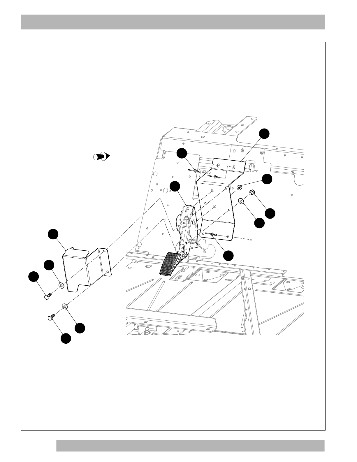
1 656066 ACCELERATOR PEDAL COVER BRACKET ................................................. 1
2 00414G6 HEX HEAD BOLT, 1/4'' - 20 X 7/8'' LG............................................................. 2
3 00559G7 FLAT WASHER, 1/4''........................................................................................ 4
4 14390G4 LOCK NUT, 1/4'' - 20........................................................................................ 4
5
6
7 641295 SINGLE SENSOR ACCELERATOR PEDAL.................................................... 1
8 645956 FLANGED HEX NUT, M8 X 1.25 ..................................................................... 2
9
10
11 655658 ACCELERATOR PEDAL MOUNTING BRACKET ........................................... 1
12 14601G11 RIVET, 3/16'' X 9/16''........................................................................................ 4

Page A-3
Notes:
ACCELERATOR
666430 Service Parts Manual

Page A-4
Notes:
ACCELERATOR
666430 Service Parts Manual
666430 Service Parts Manual
Page B-1
BATTERY SYSTEM
14
15
4
6
6
6
6
6
6
1
4
8
2
3
11
13
16
7
7
2
8
4
Front of Vehicle
5
10
12

THE USE OF NON U.L. PARTS WILL VOID ANY U.L. LISTING.
When ordering parts, please specify the model and serial number of the product.
* Indicates a component that is not available as an individual part.
*** Indicates consult Customer Service Department for additional information.
ITEM PARTNO. 12345 DESCRIPTION QTY.
Page B-2
BATTERY SYSTEM
666430 Service Parts Manual
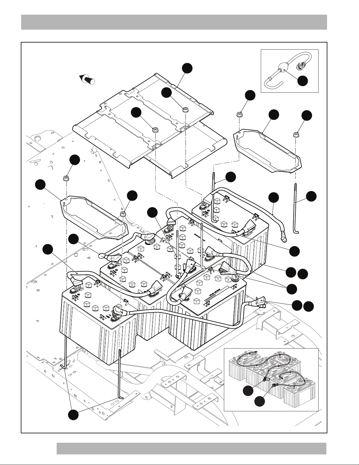
1 629435 BATTERY HOLD DOWN BRACKET, 4 - 12V .................................................. 1
2 631988 HOLD DOWN BRACKET, 1 - 12V.................................................................... 2
3 647050 BATTERY, 12V................................................................................................. 6
4 70386G01 TIE DOWN BOLT, 5/16" - 18 X 11 3/4" LG....................................................... 6
5 01101G01 TIE DOWN BOLT............................................................................................. 2
6 11027G1 FLANGED LOCK NUT, 5/16" - 18.................................................................... 8
7 628624 BATTERY WIRE, 12.5" LG .............................................................................. 3
8 628628 BATTERY WIRE, 16" LG ................................................................................. 2
9
10 628630 BATTERY WIRE, 22" LG ................................................................................. 1
11 628631 BATTERY WIRE, 32" LG ................................................................................. 1
12 676122 TROJAN HAND PUMP KIT.............................................................................. 1
13 652295 BATTERY, 12V................................................................................................. 6
14 620820 HYDRO-LINK SNAKE ASSEMBLY.................................................................. 1
15 630974 BATTERY FILL SNAKE.................................................................................... 1
16 670936 BATTERY WIRE, 38" LG ................................................................................. 1

666430 Service Parts Manual
Page B-3
BATTERY SYSTEM
1
THE USE OF NON U.L. PARTS WILL VOID ANY U.L. LISTING.
When ordering parts, please specify the model and serial number of the product.
* Indicates a component that is not available as an individual part.
*** Indicates consult Customer Service Department for additional information.
ITEM PARTNO. 12345 DESCRIPTION QTY.
Page B-4
BATTERY SYSTEM
666430 Service Parts Manual
1645743 BATTERY CHARGER, D PLUG 72V 1500W .................................................. 1

Page B-5
Notes:
BATTERY SYSTEM
666430 Service Parts Manual

Page B-6
Notes:
BATTERY SYSTEM
666430 Service Parts Manual
666430 Service Parts Manual
Page C-1
BODY
B
A
B
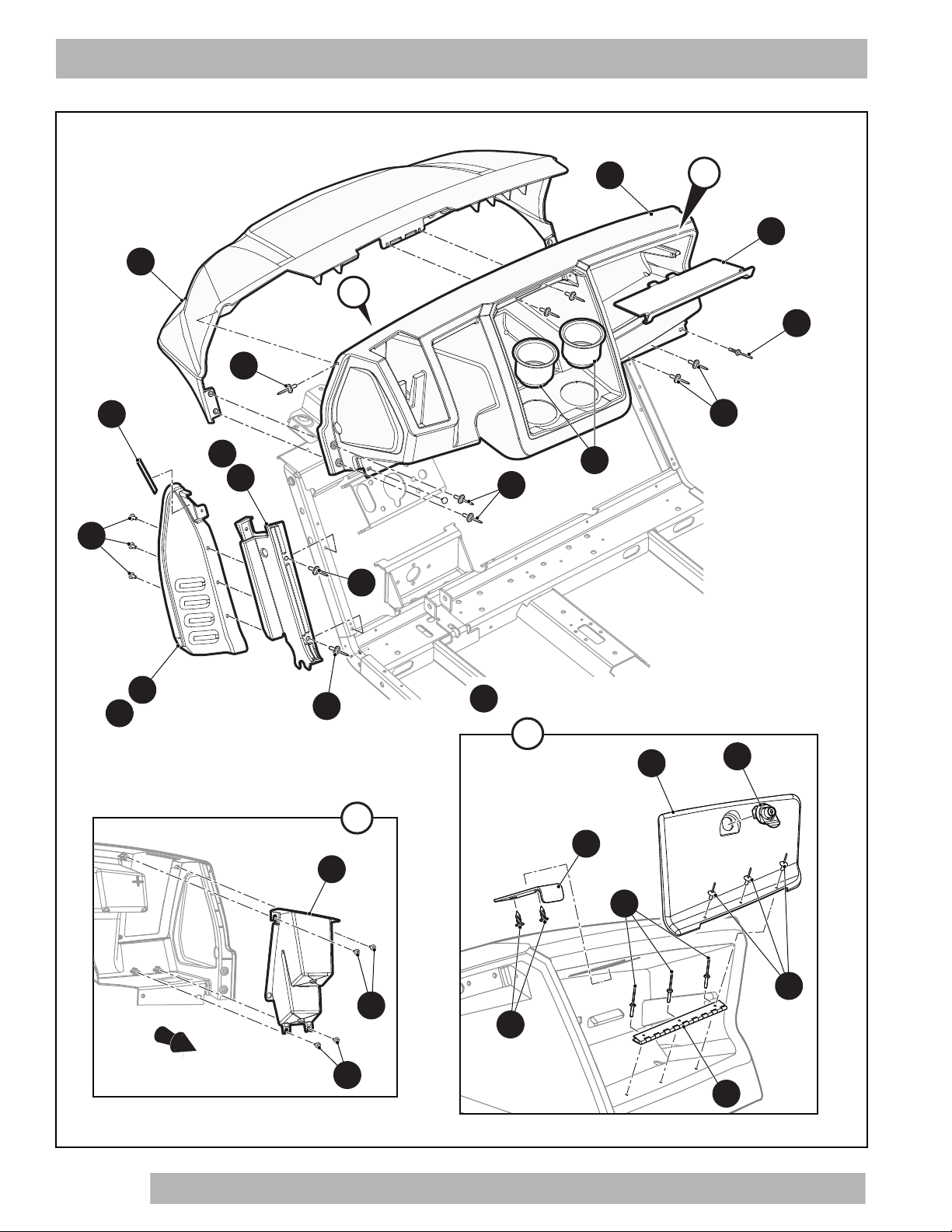
21 GLOVE BOX DOOR ASSY (PASSENGER SIDE)
includes items 22 - 25
22
25
26
28
27
24
23
A
1
5
13
16
18
6
14
17
2
19
19
15
7
10
9
9
11
2
Front of Vehicle
8
Table of contents
Other Textron Off Road Electric Vehicle manuals


