Textron Off Road RECOIL iS Guide

SERVICE PARTS MANUAL
640768-X
REVISED SEP 2017ISSUED AUGUST 2014


Page i
640768 Service Parts Manual
SERVICE PARTS MANUAL
72V ELECTRIC POWERED VEHICLES
RECOIL iS
STARTING MODEL YEAR 2015
CALIFORNIA Proposition 65 Warning
WARNING: Motor vehicles may contain fuels, oils and fluids, battery posts, terminals, and related accessories which
contain lead and lead compounds and other chemicals identified by the State of California to potentially cause can-
cer, birth defects, and other reproductive harm. These chemicals are found in vehicles, vehicle parts and accessories,
both new and replacements. During maintenance, these vehicles generate used oil, waste fluids, grease, fumes, and
particulates, all identified by the State of California to potentially cause cancer, birth defects, and other reproductive
harm.
Never modify the vehicle in any way that will alter the weight distribution of the vehicle, decrease its stability or increase the speed be-
yond the factory specifications. Such modifications can cause serious personal injury or death. Textron Specialized Vehicles prohibits
and dis-claims responsibility for any such modifications or any other alteration which would adversely affect the safety of the vehicle.
TSV reserves the right to incorporate engineering and design changes to products in this manual, without obligation to include these
changes on units sold previously.
The information contained in this manual may be revised periodically by TSV, and therefore is subject to change without notice.
TSV DISCLAIMS LIABILITY FOR ERRORS IN THIS MANUAL, and SPECIFICALLY DISCLAIMS LIABILITY FOR INCIDENTAL AND CONSE-
QUENTIAL DAMAGES resulting from the use of the information and materials in this manual.
These are the original instructions as defined by 2006/42/EC.
TO CONTACT US:
Textron Specialized Vehicles, Inc.
1451 Marvin Griffin Road
Augusta, Georgia, USA 30906-3852
NORTH AMERICA:
Technical Assistance & Warranty PHONE: 1-800-774-3946, FAX: 1-800-448-8124
Service Parts PHONE: 1-888-438-3946, FAX: 1-800-752-6175
International: PHONE: 001-706-798-4311, FAX: 001-706-771-4609
For parts and repair, contact local dealer. Dealers can be located at www.TEXTRONOFFROAD.com

Page ii
NOTES
640768 Service Parts Manual
This vehicle has been designed and manufactured in the United States of America (USA).
The Standards and Specifications listed in the following text originate in the USA unless
otherwise indicated.
The use of non Original Equipment Manufacturer (OEM) approved parts may void the
warranty.
BATTERY PROLONGED STORAGE
Batteries self-discharge over time. The rate of self-discharge varies depending on the ambi-
ent temperature, the age and condition of the batteries.
Fully charged batteries will not freeze in winter temperatures unless the temperature falls
below -75°F (- 60°C).
For winter storage, the batteries must be clean, fully charged and disconnected from any
source of electrical drain.
The battery charger may be left connected to the vehicle to maintain a full charge on the bat-
teries, provided the charger is plugged into an active electrical source. If power to the elec-
trical source is disconnected or interrupted, the battery charger will continue to check the
charge on the battery pack. This will draw power from the battery pack and eventually drain
the batteries if power is not restored in a timely manner.
As with all electric vehicles, the batteries must be checked and recharged as required or at
a minimum of 30 day intervals.
Check and maintain the proper fluid level in all battery cells during the storage period.
Proper fluid level is required for maximum battery performance.
BATTERY DISPOSAL
Lead-acid batteries are recyclable. Return whole scrap batteries to distributor, manufacturer
or lead smelter for recycling. For neutralized spills, place residue in acid-resistant
containers with absorbent material, sand or earth and dispose of in accordance with local,
state and federal regulations for acid and lead compounds. Contact local and/or state
environmental officials regarding disposal information.
WARRANTY
Separate inserts supplied in packaging with the vehicle provide information on Product
Warranty and Emissions Warranty. Failure to follow instructions for emission parts replace-
ment may violate Federal Law (40 CFR part 1068.105 (b)) and be subject to fines and other
penalties as described in the Clean Air Act.

Page iii
640768 Service Parts Manual
SECTION Page No.
TABLE OF CONTENTS
HOW TO USE THE SERVICE PARTS MANUAL ......................................................................................................v
ACCELERATOR ..................................................................................................................................................A - 1
BATTERY SYSTEM.............................................................................................................................................B - 1
BODY...................................................................................................................................................................C - 1
BRAKES ..............................................................................................................................................................D - 1
ELECTRICAL SYSTEM .......................................................................................................................................E - 1
FRONT AXLE & REAR AXLE.............................................................................................................................. F - 1
FRONT SUSPENSION AND STEERING ........................................................................................................... G - 1
MOTOR................................................................................................................................................................H - 1
OPERATOR PROTECTION SYSTEM (OPS)...................................................................................................... J - 1
REAR SUSPENSION ..........................................................................................................................................K - 1
SEATING ............................................................................................................................................................. L - 1
TRUCK BED ....................................................................................................................................................... M - 1
WEATHER PROTECTION .................................................................................................................................N - 1
WHEELS AND TIRES..........................................................................................................................................P - 1

Page iv 640768 Service Parts Manual
NOTES

Page v
640768 Service Parts Manual
HOW TO USE THE SERVICE PARTS MANUAL
This manual is divided into several sections:
•GENERAL INFORMATION
•ILLUSTRATED PARTS BREAKDOWN
•APPENDIX
The first section, GENERAL INFORMATION, contains the following information:
•WARRANTY INFORMATION
•GENERAL INDEX
•HOW TO USE THE SERVICE PARTS MANUAL
The second section, ILLUSTRATED PARTS BREAKDOWN, contains illustrations and parts lists for all systems of your
vehicle.
The third section, APPENDIX, contains a listing of specialty products and accessories.
USE OF THE MANUAL
To use this manual, consult the GENERAL INDEX to locate the information or illustration required.
Introduction of some revisions varies due to supply of components; therefore, it is possible that various combinations of
components may be found that are not directly reflected by each illustration. Consult the illustration that best suits your
situation and then contact the Service Parts Department. It is important that the serial number of your vehicle and its
model number be supplied to Service Parts when ordering any replacement components.
Locate the serial number plate (see BODY located in the Illustrated Parts Breakdown section of this manual for its loca-
tion) and note the complete number shown on the plate.
Page vi 640768 Service Parts Manual
HOW TO USE THE SERVICE PARTS MANUAL
1. WHEN THE PART NUMBER IS NOT KNOWN
•Determine the function and application of the part required. Turn to the General Index and select the most
appropriate title.
•Turn to the page number indicated and locate the desired part on the illustration.
•From the illustration, obtain the item number assigned to the desired part. Refer to the accompanying
description for specific information regarding the part.
2. IF YOU KNOW THE PART NUMBER
•Locate the part number or description in the appropriate column on the parts list page.
NOTE: It is suggested that you confirm that the part selected is correct by verifying it with the pictorial representation on
the illustrated page.
Should an asterisk (*) appear in the part number column on the parts list page, read upwards until a part number is
found. The part number is the lowest assembly sold by Service Parts and the asterisk (*) indicates that the part depicted
is not available for purchase.
NOTE: Descriptions are indented under the assembly that they are used on. That assembly is, in turn listed under the
assembly that it is used on. This process is repeated until the highest final assembly is reached.
To facilitate the maintenance and repair of the vehicle, a Technician’s Repair and Service Manual is
available from the Service Parts Department.
Title Title
Left hand
illustration page Parts list (continued on
rear of page if required)
Front of Vehicle
123
101
100
99
98
120
74
70
71
64
63
65
66
67
121
122
114
119
115
111
73
72
112
118
116
113
62
69
94
96
95
82,87
81,86
84,89
83,88
102,104
105
79
91
92
107
106
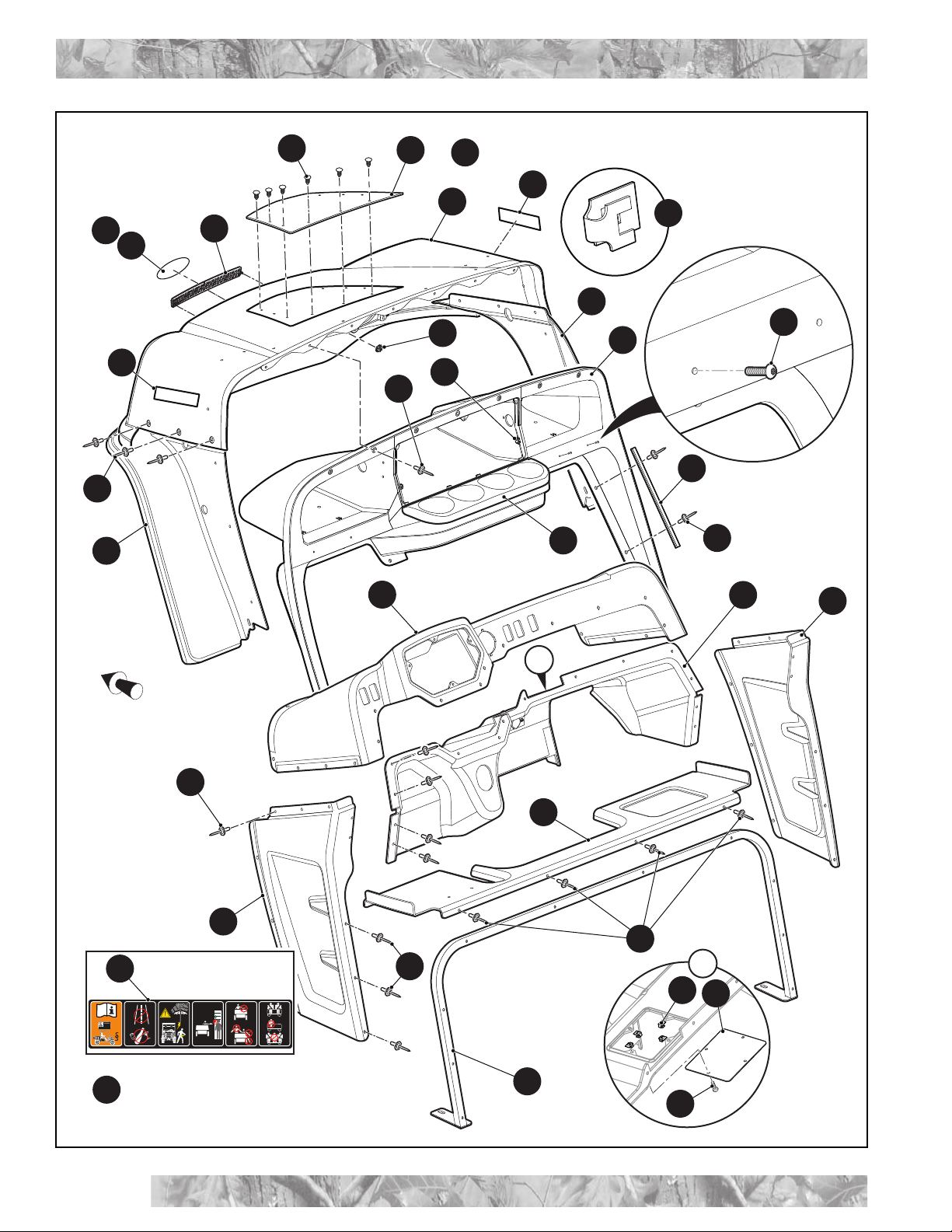
62 - Includes Items 63 - 66, 69 - 74
70 -Incl
udes Items 71 - 74
81- Includes Items 82 - 84
86 - Includes Items 87 - 89
94 - Includes Items 95, 96
111 - Includes Items 112 - 114
118 - Includes Items 119 - 121
126 - Includes Items 127 - 131
103
*See Body Section for
decal information
127
128129
130
131
126

Page vii
640768 Service Parts Manual
HOW TO USE THE SERVICE PARTS MANUAL
3. COLOR CODE FOR BODY COMPONENTS
The last two digits of the part number for the body part will denote the color code. Locate the part number for the cowl,
rear body, seat pod, side panel or seat wrap then locate your color in the list below. Replace the last ** or XX with the
two digit color code.
CODE # DESCRIPTION
38 BRIGHT WHITE
39 FLAME RED
72 MATTE BLACK
78 REALTREE XTRA DIPPED
80 REALTREE MAX 5 DIPPED
Service Parts Manual
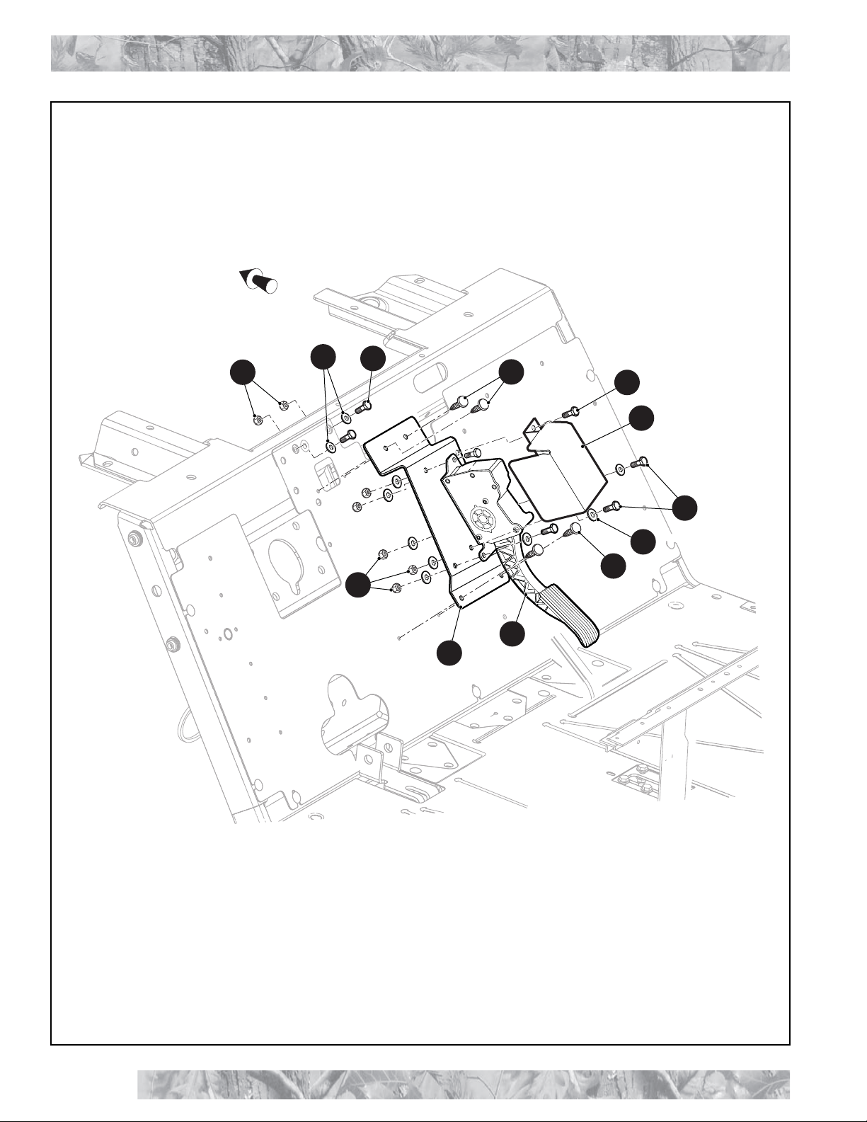
ACCELERATOR
Page A-1 640768 Service Parts Manual
Front of Vehicle
5
5
6
1
4
7
3
2
2
10
9
3

THE USE OF NON U.L. PARTS WILL VOID ANY U.L. LISTING.
When ordering parts, please specify the model and serial number of the product.
* Indicates a component that is not available as an individual part.
*** Indicates consult Customer Service Department for additional information.
ITEM PARTNO. 12345 DESCRIPTION QTY.
Service Parts Manual
ACCELERATOR
Page A-2
Service Parts Manual
640768 Service Parts Manual
1 626739 ACCELERATOR PEDAL................................................................................. 1
2 14601G11 RIVET, 3/16" X 9/16"....................................................................................... 4
3 00414G6 HEX HEAD BOLT, 1/4" - 20 X 7/8" LG............................................................ 5
4 00559G7 FLAT WASHER, 1/4"....................................................................................... 10
5 14390G4 HEX NUT, 1/4" - 20 ......................................................................................... 7
6 635422 ACCELERATOR PEDAL MOUNTING BRACKET.......................................... 1
7 630045 ACCELERATOR PEDAL COVER................................................................... 1
8
9 01110G01 FLAT WASHER, 1/4"....................................................................................... 2
10 302288 HEX HEAD BOLT, 1/4" - 20 X 1" LG............................................................... 2

Service Parts Manual
Notes:
ACCELERATOR
Page A-3 640768 Service Parts Manual

Service Parts Manual
Notes:
ACCELERATOR
Page A-4
Service Parts Manual
640768 Service Parts Manual

Service Parts Manual
BATTERY SYSTEM
Page B-1 640768 Service Parts Manual
To Solenoid
To
Controller
16
11
8
9
6
2
Front of Vehicle
7
6
10
3
3
14
15
14
4
4
5
1
13
12

THE USE OF NON U.L. PARTS WILL VOID ANY U.L. LISTING.
When ordering parts, please specify the model and serial number of the product.
* Indicates a component that is not available as an individual part.
*** Indicates consult Customer Service Department for additional information.
ITEM PARTNO. 12345 DESCRIPTION QTY.
Service Parts Manual
BATTERY SYSTEM
Page B-2
Service Parts Manual
640768 Service Parts Manual
1 616229 BATTERY HOLD DOWN WELDMENT........................................................... 3
2 612626 BATTERY, 8V.................................................................................................. 8
3 01101G01 TIE DOWN BOLT............................................................................................ 2
4 11027G1 FLANGED LOCK NUT, 5/16" - 18................................................................... 8
5 629583 BATTERY HOLD DOWN WELDMENT, 6 - 8V................................................ 1
6 70386G01 TIE DOWN BOLT............................................................................................ 4
7 628624 BATTERY WIRE, 12.5" ................................................................................... 2
8 628628 BATTERY WIRE, 16" ...................................................................................... 1
9 628629 BATTERY WIRE, 22" ...................................................................................... 3
10 628630 BATTERY WIRE, 22" ...................................................................................... 1
11 628631 BATTERY WIRE, 32" ...................................................................................... 1
12 628632 BATTERY WIRE, 92" ...................................................................................... 2
13 642123 BATTERY FILL SYSTEM
(FOR VEHICLES MANUFACTURED FROM 1 DECEMBER 2014) ............... 1
14 604197 BATTERY HOOK BOLT .................................................................................. 2
15 614382 BATTERY, 8V (FLOWRITE)............................................................................ 1
16 629127 BATTERY FILL SYSTEM
(FOR VEHICLES MANUFACTURED BEFORE 1 DECEMBER 2014) ........... 1
Service Parts Manual
BATTERY SYSTEM
Page B-3 640768 Service Parts Manual
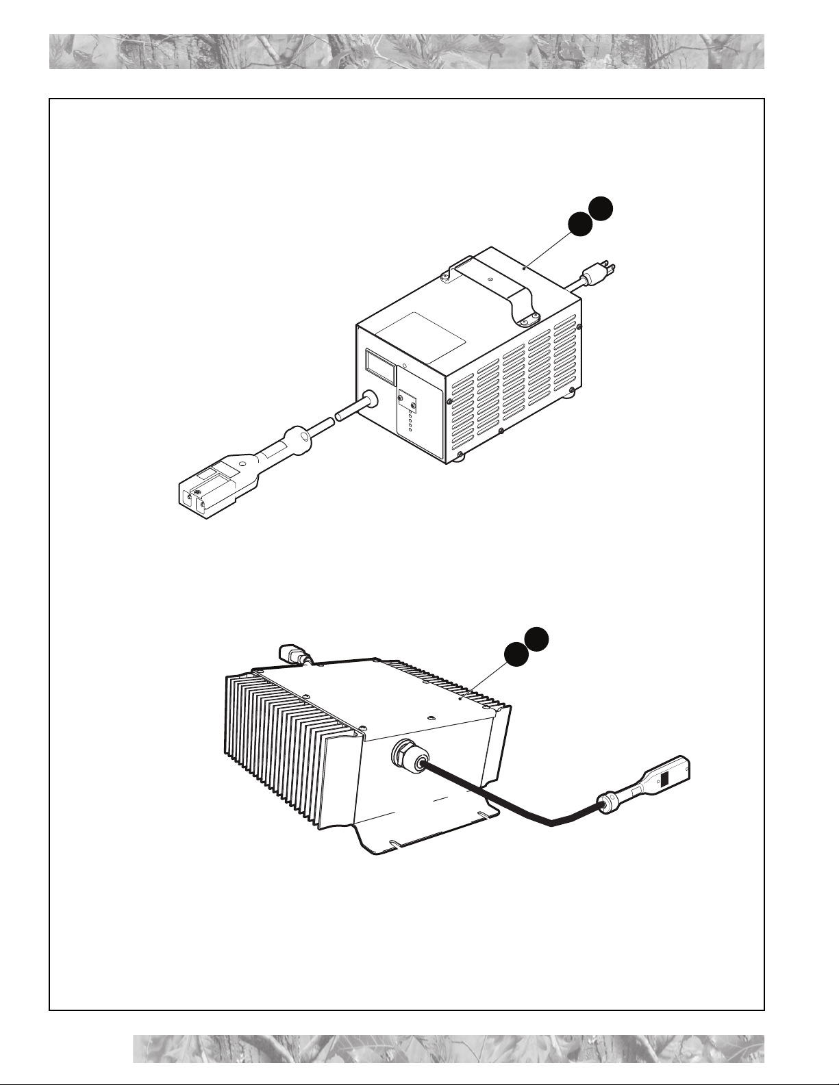
1
2
3
5

THE USE OF NON U.L. PARTS WILL VOID ANY U.L. LISTING.
When ordering parts, please specify the model and serial number of the product.
* Indicates a component that is not available as an individual part.
*** Indicates consult Customer Service Department for additional information.
ITEM PARTNO. 12345 DESCRIPTION QTY.
Service Parts Manual
BATTERY SYSTEM
Page B-4
Service Parts Manual
640768 Service Parts Manual
1 626766 BATTERY CHARGER WITH HANDLE, 72V, 12A........................................... 1
2 630758 BATTERY CHARGER (INTERNATIONAL) WITH HANDLE, 72V, 12A........... 1
3 634567 BATTERY CHARGER, D PLUG, 72V ............................................................. 1
4
5 645743 BATTERY CHARGER, D PLUG, 72V ............................................................. 1

Service Parts Manual
Notes:
BATTERY SYSTEM
Page B-5 640768 Service Parts Manual

Service Parts Manual
Notes:
BATTERY SYSTEM
Page B-6
Service Parts Manual
640768 Service Parts Manual
Service Parts Manual
BODY - FRONT
Page C-1 640768 Service Parts Manual
24
20
21
1
2
35
6
19
15
23
22
23
7
10
25
16
18
27
11
9
12
3
4
INSTRUMENT PANEL ASSEMBLY includes items 10 - 12
23
23
Front of Vehicle
12
23
26 DASH ASSEMBLY, STEERING COLUMN
includes items 27 - 31
32
33
A
28
30
29
A
665091
MIN 150 cm
59 inches
www.textronoffroad.com
31
Table of contents
Other Textron Off Road Electric Vehicle manuals


Popular Electric Vehicle manuals by other brands

Kia
Kia OPTIMA plug-in hybrid Emergency Rescue Guide Manual

Ezgo
Ezgo EXPRESS L4 Service manual

Cushman
Cushman LSV 800 Service & parts manual

PlayActive
PlayActive MINI Beachcomber Owner's manual with assembly instructions

IPC
IPC TIGER 500S instruction manual

Mercedes-Benz
Mercedes-Benz EQS 2023 Operator's manual