. . . . . . . . . . . . . . . . . . . . . . . . . . . . . . . . . . . . . .. . . . . . . . . . .
-in Hybrid Electric Vehicle Identification .. . . . . . . . . . . . . .
General Vehicle Description
. . . . . . . . . . . . . . . . . . . . . . . . . . . . . . . . . . . . . . . . . . . . . . . . .. .
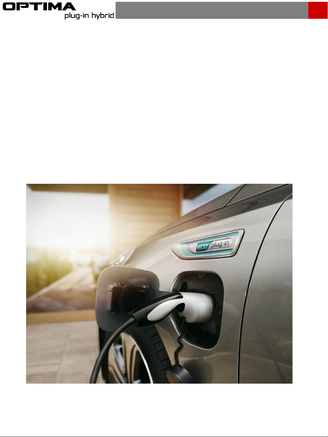
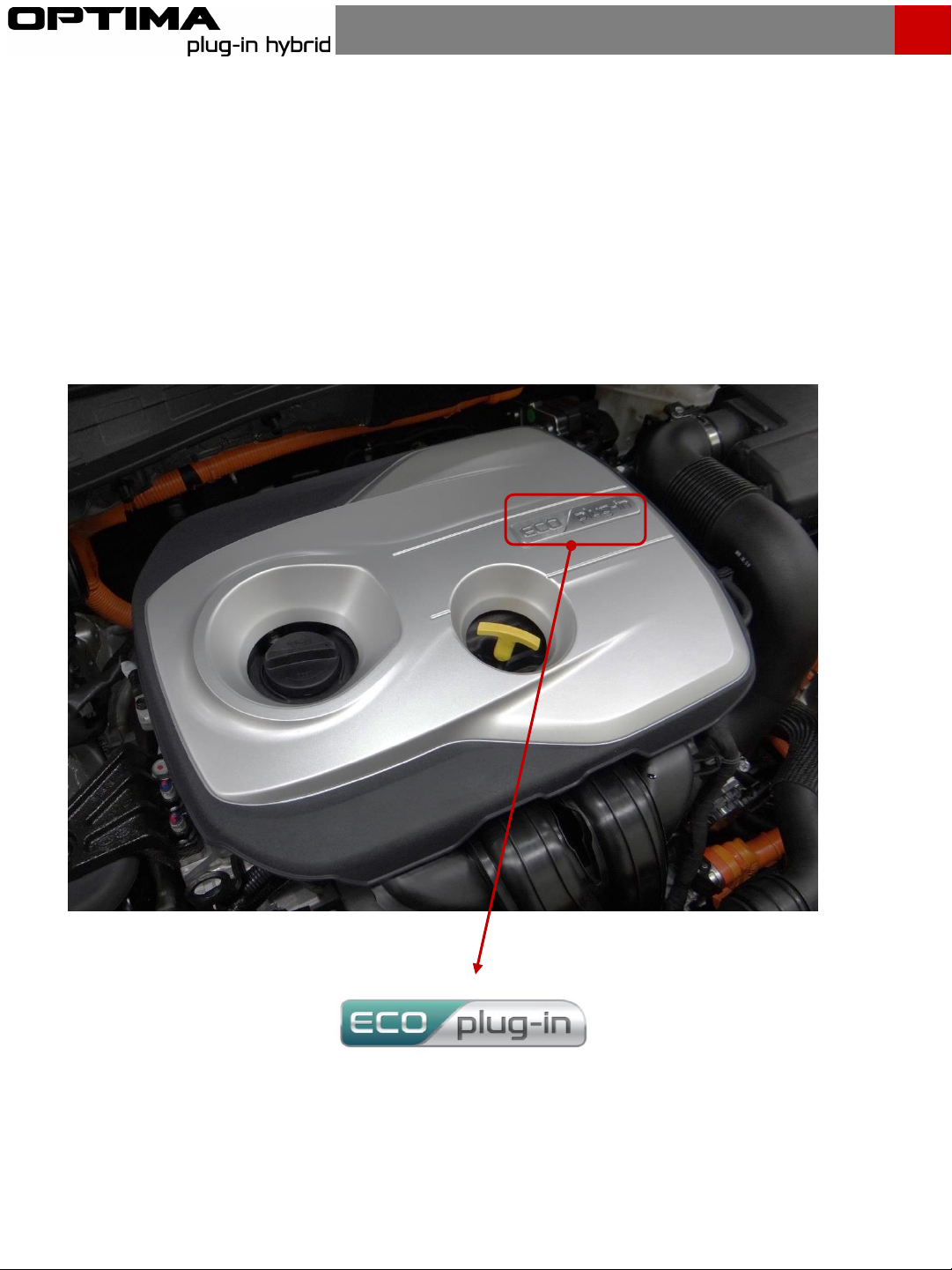
Identifying a Kia Optima Plug
-in Hybrid Electric Vehicle . . . . . . . . . . . . . . . . . . . . . . . . . . . . . .
Optima PHEV Main Electric Systems
. . . . . . . .. . . . . . . . . . . . . . . . . . . . .
Power Electric Specification
. .. . . . . . . . . . . . . . . . . . . . . . . . . . . . . . . . . . . . . . . . . . . . . . . . .
Components . . . . . . . . . . . . . . . . . . . . . . . . . . . . . . . . . . . . . . . . . . . . . . . . . . . . . .
Airbag system (SRS: Supplemental Restraint System). . . . . . . . . . . . . . . . . . . . . . . . . . . . . . . . .
. . . . . . . . . . . . . . . . . . . . . . . . . . . . . . . . . . . . . . . . . .
. . . . . . . . . . . . . . . . . . . . . . . . . . . . .. . . . . . . . . .. . . . . . . . . . . . . . . . . . . . . . . . . . . .
. . . . . . . . . . . . . . . . . . .. . . . . .. . . . . . . . . . . . . . . . . . . . . . . . . . . . . . . .
Contents
. . . . . . . . . . . . . . . . . . . . . . . . . . . . . . . . . . . . . . . . . . . . . . . . . . . . . . . . .
Vehicle Description. . . . . . . . . . . . . . . . . . . . . . . . . . . . .
. . . . . . . . . . . . . . . . . . . . . . . . . . . .
Initial Response: Identify, Immobilize and Disable
. . . . . . . . . . . .. . . . . . . . .. . . . . . . . . . . . . .
. . . . . . . . . . . . . . . . . . . . . . . . . . . . . . . . . . . . . . . . . . . . . . . . . . . . . .
.. . . . . . . . . . . . . . . . . . . . . . . . . . . . . . . . . . . . . . . . . . . . . . . . . . . . . . . . . . . . . .
Submerged or Partially Submerged Vehicles
. . . . . . . . . . . . . . . . . . . . . . . . . . . . . . . . . .. . .
High Voltage Battery Damage and Fluid Leaks
. . . . . . . . . . . . . . . . . . . . . . . . . . . . . . . . . . . .
4
-CUT ZONES. . . . . . . . . . . . . . . . . . . . . . . . . . . . . . . . . . . . . . . . . . . . . . . . . . . . . . . .