TFC Tower APUMP-HE Series User manual
EEI≤0.20
Energy-saving Pipeline Canned
Motor Pump
APUMP-HE Series
Installation and
Operation Manual
TFC Group LLP

Notes:
01. Read the installation manual 11. Some models are not suitable for
carefully before installation and drinking water.
use. 12. The liquid may be high-temperature
02. The manufacturer will not be liable and high-pressure; therefore, the
for any personal injury, pump liquid in the system must be
damage and other property completely drained or the shut-off
damage due to failure to comply valves on both sides must be
with safety warnings closed before moving and
dismantling the pump to prevent
a burn hazard.
03. The installers and operators must
comply with local safety regulations.
13. If removing the exhaust bolt, high-
temperature and high-pressure
liquid will be released. Measures
must be taken to safely contain
any released liquid.
04. The user must confirm that only
qualified personnel with
professional certification and
proficiency of this manual are
permitted to install and maintain this
product.
05. The pump is rated Ip44 and must not
be installed in a place that is damp or
may be splashed by water.
14. Ventilation must be ensured in
summer or high ambient
temperature conditions to avoid
condensation that may cause
electrical malfunctions.
06. For convenient access of
maintaince, a shut-off valve shall be
installed on each side of the pump
15. If there is a risk of frost damage,
install a frost protection thermostat,
or drain down the system in order
to avoid frost damage to the pump
body.
07. The power supply of the pump must
be disconnected before installation
andmaintainace.
08. For domestic hot water, copper or
stainless steel pump body shall be
used.
16. If the pump is left unused for a long
time, please close the pipe valve in
the inlet and outlet of the pump and
disconnect the power supply.
17. If the flexible cord of cable is
damaged, it must be replaced by a
qualified person.
18. Please close the valve at the inlet of
the pump and disconnect power of the
pump immediately if overheating
10. Do not start the pump without
liquid.
01
APUMP-HE
09. In hard water areas use
appropriate water treatment
additives to prevent calcium
deposits, which can block
pipelines and / or the pump
impeller.
or abnormality of motor is detected, and contact your vendor or service center
immediately.
19. If problem cannot be addressed according to the manual, please close the valves
on the inlet and outlet of the pump immediately, cut off power supply and contact
your vendor or service center immediately.
20. This product shall be put in a place out of reach of children. After installation, take
an isolation measures to avoid access of children.
21. This product shall be stored in a dry, well ventilated and cool place under room
temperature.
Warning
Before installation, you must carefully read the installation
and operation manual. The installation and use of the
equipment must comply with local regulation and
applicable operation standards.
Warning
Those who have weak physical strength, react slowly
or lack experience and knowledge (including children) can
use this motor pump only under the monitoring and
direction of his/her safety personnel.
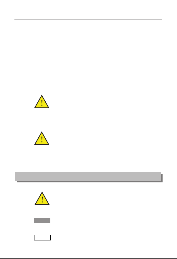
Caution
Note
Warning
Failure to comply with this safety instruction may lead to
personal injury!
Failure to comply with this safety instruction may lead to
equipment malfunction or damage!
Note or instruction for easy and safe operations.
1. Signs
02
APUMP-HE

magnet
2. General
2.1. The APUMP-HE circulation
pump is designed for use
in domestic heating and hot
water systems.
The product is most applicable to the
following systems:
·
system
·variable-temperature pipeline heat
supply system
·heat supply system with night mode
·HVAC system
· Industrial circulation system
domestic heating and domestic
water supply system
This pump is equipped with permanent-
motor and differential pressure
controller, capable of automatically &
continuously adjusting motor performance
to meet the actual needs of the system.
This pump is equipped with control
panel on the front for easy operation
by users.
stable and variable-flow heat supply
·
2.2. Advantages
Easy installation and start-up
(
motor pump needs no adjustment
and can be readily started and
will adjust automatically to meet
the actual needs of the systems.
High-degree comfort
·Low operational noise of motor pump
and whole system.
·Provided with self adaptivc mode
AUTO
Initial setting). In most cases, the
03
APUMP-HE

3.1 Ambient Temperature
Ambient temperature: 0 40
3.2. Relative humidity(RH):
Max. humidity: 95%
3.3. Medium (liquid delivery) temperature
Liquid delivery temperature: +2℃110
To avoid condensation in control box and the stator, the temperature of liquid
pumped by the motor pump must be always higher than ambient temperature.
3.4. System Pressure
Maximum pressure 1.0MPa(10bar).
3.5. Degree of Protection
IP 44
3.6. Inlet Pressure
.
℃~+ ℃
~℃
Liquid Temperature
<85℃90℃110℃
Inlet Pressure
0.05bar 0.28bar 1bar
0.5m head 2.8m head
3.7. Pumping Liquid
The pumping liquid includes thin, clean, non-corrosive and non-explosive liquid
which shall not contain any solid particles, fiber or mineral oil, and the pump must
definitely not be used to pump inflammable liquid such as rapeseed oil and gasoline.
If the pump is used in a place with relatively high viscosity, the pump has lower
performance. So when choosing a pump, the viscosity of liquid must be taken into
account.
3. Operating Conditions
10m head
04
APUMP-HE

4.1.
·
pump case indicates the flow direction of liquid through the pump.
·When installing the motor pump in the pipeline, the two gaskets supplied must be
installed at the inlet and outlet.
·During the installation, the motor pump shaft must be horizontal.
Installation
When installing APUMP-HE series circulation pump, the arrow on the motor
4. Installation
05
APUMP-HE

4.2. Position of Junction Box
06
4.3.
The junction box can be rotated in a step of 90°.
The procedures for changing the position of junction box are as follows:
1. Close the valves at the inlet and outlet and release the pressure;
2. Unscrew and remove the four socket head screws that fasten the pump body;
3. Rotate the motor to the required position and align the four screw holes;
4. Install the four socket head screws again and fasten them clockwise making
sure they are fully tightened;
Changing Position of Junction Box
APUMP-HE
5. Open the valves at the inlet and outlet.

Warning
Pumping liquid may be high-temperature and high-pressure;
therefore, the liquid in the system must be completely drained or the
valves on both sides of motor pump must be closed before removing
the socket head screws.
4.4. Thermal Insulation of Motor Pump Body
Limiting the heat loss of motor pump body and pipeline.
Motor pump body and pipeline should be thermally insulated
to reduce their heat loss.
Do not insulate or cover the junction box and control panel.
Caution
Note
07
APUMP-HE
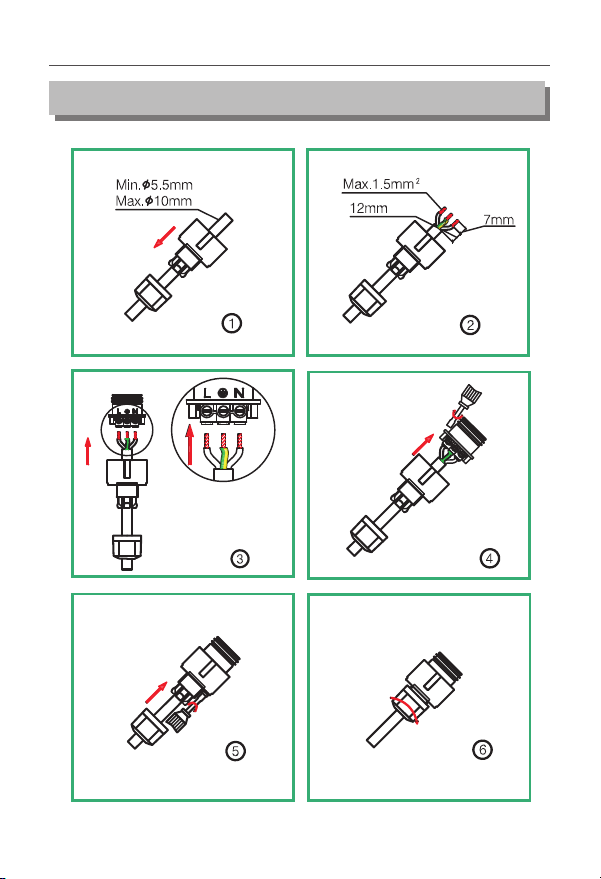
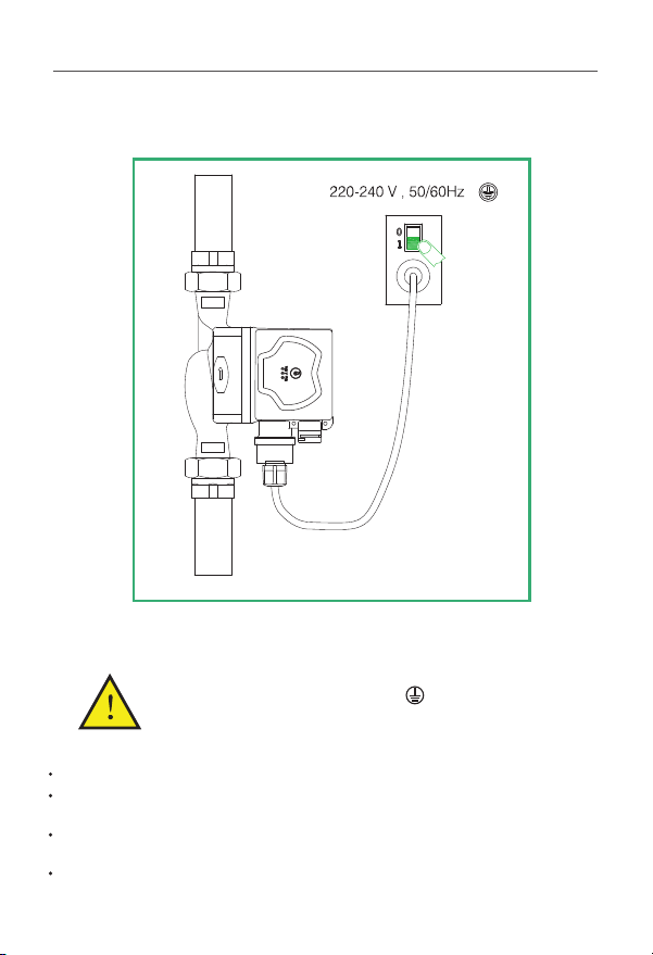
5. Electrical Connection
08
APUMP-HE
Electrical connection and protection shall comply with
local codes and norms.
Warning
The motor pump must be earthed
The motor pump must be connected to an external power switch,
with 3mm minimum contact gap in both poles.
.
·
·Check if the supply voltage and frequency are the same as parameters indicated on the
nameplate of the motor pump.
·Connect the motor pump and power supply with the plug supplied together with the
pump.
·After the power is supplied, the indicator lamp on the control panel is ON.
APUMP-HE series circulation motor pump needs no protection from external motor.
09
APUMP-HE

6. Control Panel
Position
Descriptions
1
2
Indication lamp area of three operation
modes set by motor pump.
Button for setting operation modes of
the motor pump.
6.1. Controls on Control Panel
6.2. Indication Lamp Area of Motor
Pump Setting
APUMP-HE series circulation motor pump has
settings which can be chosen with the button.
The motor pump settings are indicated with
different indication lamp areas.
three
three
10
Button Times
Indication Lamp Area
0
1
2
AUTO ( )
Initial setting
MIN
MAX
Descriptions
Self-adaptive (AUTO)
Constant Speed Curve, Velocity Min
Constant Curve, Velocity MaxSpeed
6.3.
By pressing the button once at 2 seconds interval, the motor pump setting mode will
change to the next in sequence.
A cycle is constituted of every presses on the button. For details, please refer
to Section 6.2.
Button for selecting motor pump settings
three
APUMP-HE
the motor pump setting to other settings.
curve.
11
7. Motor Pump Setting
7.1. Motor Pump Setting Based on System Type
Initial setting AUTO Self-adaptive mode
Recommended and available pump setting
= ( )
·
on the actual heat demand of the system. Self adaptive mode adjusts over time to
find the most effective setting, so before changing the motor pump setting, maintain
AUTO (Self Adaptive Mode) mode setting for at least one week.
· If you select to change back to AUTO (Self Adaptive Mode) mode, the APUMP-HE
motor pump can memorize its last setting in AUTO mode and continue adjusting the
performance automatically.
AUTO (Self Adaptive Mode) mode can adjust the performance of motor pump based
· It may take several minutes or even hours to reach the optimal operation mode after
motor pump setting is changed from the optimal setting (the “Recommended above
mention”) to one of the other optional setting. If the optimal setting of motor pump
fails to enable each room to obtain desired heat distribution, then you should change
· Please refer to Section 8.1 for the relations between pump setting and performance
8.1. Relations between Pump Setting and Performance
8. Motor Pump Setting and Performance
APUMP-HE

Proportional
12
AUTO
Setting)
(Initial
AUTO function will automatically control the
pump performance within the specified scope.
adjust pump performance based on system scale;
adjust pump performance based on load variance
within a period of time;
Under the AUTO mode, the pump will be set to
proportional pressure control;
Max
It runs on the constant curve in a constant velocity.
In the Velocity Max mode, the pump is set to work
on the highest curve under all working conditions.
Min Velocity Min
Velocity Max
Highest to
Lowest
Pressure Curve
It runs on the constant curve in a constant velocity.
In the Velocity Min mode, the pump is set to work
on the lowest curveunder all working conditions.
Functions
Setting Pump
Characteristics
Curve
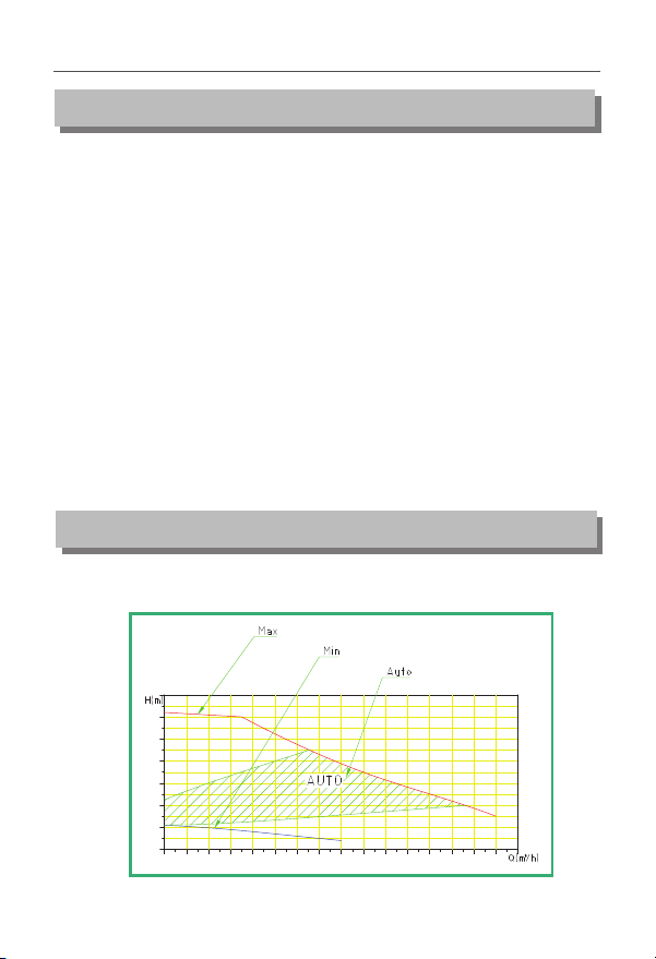
9. Performance Curve
9.1.
Every setting of the motor pump has corresponding performance curve (Q/H curve).
However AUTO (Self Adaptive Mode) mode covers just one performance scope.
The input power curve (P1 curve) belongs to every Q/H curve. Power curve represents
the power consumption of motor pump in given Q/H curve with Watt as the unit.
P1 value corresponds to the readings taken from the monitor of motor pump.
Guide on Performance Curve
APUMP-HE
13
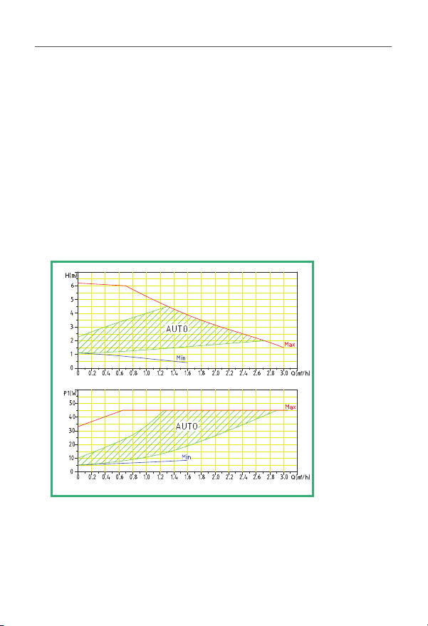
92.
The followings are applicable to the performance curve specified in the APUMP-HE
series manual:
·
· ℃.
· All curves represent averaged value, and shall not be used as guarantee curve. If a
specific performance is needed, then separate measuring shall be conducted.
· Velocity Max, Min curves have all been marked.
· The applicable Kinetic viscosity of the curve υ=0.474 mm²/s(0.474CcST)
.Curve conditions
Test liquid: air-free water.
Applicable density of curve ρ=983.2 kg/m³, and liquid temperature +60
9.3. Performance Curve
APUMP-HE
APUMP-HE

14
APUMP-HE 21030001
10. Features
No.
Descriptions
1
2
3
4
Company name (brand)
Pump Type
Date of manufacture: the first six numbers
Serial number: the rest four numbers
5
Number
6
7
8
Highest Liquid Temperature
Certification Mark
Rotation Direction
9
Protection Grade
10
Insulation class
11
Energy Index
12
Frequency (Hz)
13
Voltage (v)
Power
(Watt)
Electricity
(ampere)
Minimum power input in minimum pattern
Minimum flow in minimum pattern
Maximum system load bearing (Mpa)
14
Minimum power input in maximum pattern
Minimum flow in maximum pattern
APUMP-HE
15
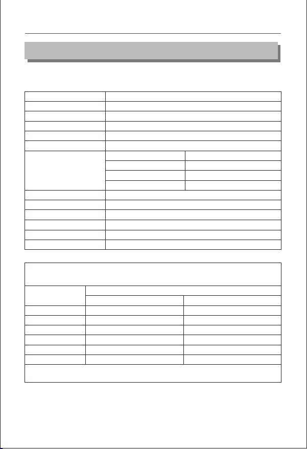
11. Technical Parameters and Installation Dimensions
11.1. Technical Parameters
Power Supply Voltage
Motor Protection
Degree of Protection
Insulation Class
Relative Humidity(RH)
System Load Bearing
Suction Port Pressure
EMC Standard
Sound Pressure Class
Ambient Temperature
Temperature Grade
Surface Temperature
Liquid Temperature
Liquid Temperature
2
10
20
30
35
40
Min. (℃)
Ambient
Temperature (℃)
0
10
20
30
35
40
220V-240V,50/60Hz,PE
The pump needs no external protection
IP 44
H
Max. 95%
1.0 MPa
Liquid Temperature
≤+ ℃85
≤+ ℃90
≤+ ℃110
The sound pressure level of pump is lower than 42dB(A)
0 40~+℃
TF110
The maximum surface temperature is not higher than +125℃
+~+℃2 110
Minimum Inlet Pressure
0.005 MPa
0.028 MPa
0.100 MPa
110
110
110
110
90
70
Max. (℃)
To prevent condensation in the junction box and rotor, the temperature of pumping
liquid of the motor pump must be always higher than ambient temperature.
For domestic hot water, it is suggested that water temperature should remains below
65℃ to reduce scaling.
EN61000-3-2 and EN61000-3-3 EN55014-1 and EN55014-2
APUMP-HE

16
11.2. Installation Dimensions
Material of
Pump Body
45
Product
Model
Power
(W)
Cast
Iron
Plastic
Copper
SS
Dimension (mm)
L1
65
L2 B1 B2 H1 H2 G
● ●●
130
82 130103130 1½"
APUMP-HE
APUMP-HE

17
Corrective Action
Symptom
Control Panel
Indication
lamp “Off”
12. Trouble-Shooting Schedule
Warning
Before conducting any maintenance and repair of the motor pump,
ensure that power supply has been cut off and will not be connected
accidentally.
Cause
Flicker two time
Motor pump
cannot
be started
Equipment fuse burned Replace the fuse
The circuit breaker of
current control or voltage control
opens
Connect the circuit
breaker
Failure of motor pump
Return to factory maintenance
Under voltage Check whether power
supply is in specified range
PCB component failure or
motor failure
Return to factory maintenance
Flicker one time High voltage
Check whether power supply
is in specified range
Flicker six time No water in the pump Open the valve and supply
water to the pump
Flicker four time Missing phase protection Return to factory
maintenance
Flicker five time Rotor blocked Remove the pump housing
and clean the rotor
Flicker three time
APUMP-HE
Table of contents
Popular Water Pump manuals by other brands

GORMAN-RUPP
GORMAN-RUPP SFEV3C Installation, operation and maintenance manual

Gardena
Gardena 13000 aquasensor Operator's manual

Sulzer
Sulzer Piranha S10 Installation, Operating and Maintenance Instruction

Edwards
Edwards STP-301 Series instruction manual

Crane
Crane Barnes 3SE-HD Series manual

SAMES KREMLIN
SAMES KREMLIN REXSON 2B453 user manual


Ingersoll-Rand
Ingersoll-Rand ARO PF20R-X Operator's manual

Medela
Medela Vario 8 c/i Service manual

Barmesa Pumps
Barmesa Pumps BMV Series Installation, operation & maintenance manual

GETINGE GROUP
GETINGE GROUP ARJOHUNTLEIGH ALPHA ACTIVE 4 Instructions for use

Agilent Technologies
Agilent Technologies 1290 infinity user manual

Becker
Becker KDT 3.100 operating instructions