manuals.online logo
Brands
  1. Home
  2. •
  3. Brands
  4. •
  5. Crane
  6. •
  7. Water Pump
  8. •
  9. Crane Barnes 3SE-HD Series User manual

Crane Barnes 3SE-HD Series User manual

A Crane Co. Company
BARNES®
SEAL KIT P/N 130182
SERVICE KIT P/N 130209
Submersible Pump
IMPORTANT! Read all instructions in this manual before operating pump.
As a result of Crane Pumps & Systems, Inc., constant product improvement program,
product changes may occur. As such Crane Pumps & Systems reserves the right to
change product without prior written noti•cation.
420 Third Street 83 West Drive, Brampton
Piqua, Ohio 45356 Ontario, Canada L6T 2J6
Phone: (937) 778-8947 Phone: (905) 457-6223
Fax: (937) 773-7157 Fax: (905) 457-2650
www.cranepumps.com Form No. 130186-Rev. C
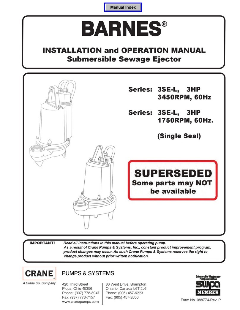
Series: 3SE-HD
Series: 3SE-L
3 HP, 3450 RPM, 60 Hz.
Series: 3SE-L
3 HP, 1750 RPM, 60 Hz.
Series: 4SE-SS
5 HP, 3450 RPM, 60 Hz.
Series: 4SE-SS
2.8 HP, 1150 RPM, 60 Hz.
Series: 4SE-SS
2.8 - 5 HP, 1750 RPM, 60 Hz.
(Single Seal)
Manual Index
2
TABLE OF CONTENTS
SAFETY FIRST............................................................................................... 3
A. SERVICE and REPAIR ....................................................................................4 - 11
SPECIAL TOOLS AND EQUIPMENT
INSULATION TESTER (MEGGER)
DIELECTRIC TESTER
SEAL TOOL KIT (107271)
PRESSURE GAUGE KIT (085343)
This manual covers the following models, there may be extra parts not
needed for your specific model. If additional parts not included in this kit are
required, please consult the explicit manual for your pump at:
http://www.cranepumps.com/downloadables/CATALOGS_OIPMs/PARTBOOK/BARNES.pdf
Series: 3SE-HD - Manual 107948, 133460
Series: 3SE-L - Manual 088774, 133410
Series: 4SE-SS - Manual 088688
Other brand and product names are trademarks or registered trademarks of their respective holders.
® Barnes is a registered trademark of Crane Pumps & Systems, Inc
1999, 2002, 11/03, 6/05, 4/06 , 9/06, 2/07 Alteration Rights Reserved
Seal Repair Kit ...... P/N - 130182 (†)
Service Kit
............. P/N - 130209 (♦)
PARTS INCLUDED IN KIT
QTY PART NO. DESCRIPTION
1 017026 †♦ O-Ring
1 062641 †♦ Pull Washer
1 061829 †♦ “V”-Ring
2 033730 †♦ Square Ring
1 062435 †♦ Mech Seal
3 079318 ♦ Wire Connector
1 057882 ♦ Retaining Ring
1 035589 ♦ Shaft Key
1 038132 ♦ Jam Nut
1 20-24-1 ♦ Washer
1 053746 ♦ Ball Bearing
6 055844 ♦ Wire Connector
6 052990 ♦ Wire Connector
1 070320 ♦ Impeller Washer
1 105149A ♦ Jumper Wire
1 105150 ♦ Wire Crimp Connector
1 111951 ♦ Barrel Crimp Terminal
1 2-31051-224 †♦ O-Ring
1 105197 ♦ Retaining Ring
3
Please Read This Before Installing Or Operating Pump.
This information is provided for SAFETY and to PREVENT
EQUIPMENT PROBLEMS. To help recognize this information,
observe the following symbols:
IMPORTANT! Warns about hazards that can result
in personal injury or Indicates factors concerned with
assembly, installation, operation, or maintenance which
could result in damage to the machine or equipment if
ignored.
CAUTION ! Warns about hazards that can or will cause minor
personal injury or property damage if ignored. Used with symbols
below.
WARNING ! Warns about hazards that can or will cause serious
personal injury, death, or major property damage if ignored. Used
with symbols below.
Only qualified personnel should install, operate and repair the
pump. Any wiring of pumps should be performed by a qualified
electrician.
WARNING ! - To reduce risk of electrical shock, pumps
and control panels must be properly grounded in
accordance with the National Electric Code (NEC) or the
Canadian Electrical Code (CEC) and all applicable state,
province, local codes and ordinances.
WARNING! - To reduce risk of electrical shock, always
disconnect the pump from the power source before
handling or servicing. Lock out power and tag.
WARNING! Operation against a closed
discharge valve will cause premature bearing
and seal failure on any pump, and on end
suction and self priming pump the heat build
may cause the generation of steam with resulting dangerous
pressures. It is recommended that a high case temperature
switch or pressure relief valve be installed on the pump body.
CAUTION ! Never operate a pump with a plug-in type
power cord without a ground fault circuit interrupter.
CAUTION! Pumps build up heat and pressure
during operation-allow time for pumps to cool
before handling or servicing.
WARNING! - DO NOT pump hazardous materials
(flammable, caustic, etc.) unless the pump is specifically
designed and designated to handle them.
Do not block or restrict discharge hose, as discharge
hose may whip under pressure.
WARNING! - DO NOT wear loose clothing that may
become entangled in the impeller or other moving parts.
WARNING! - Keep clear of suction and discharge
openings. DO NOT insert fingers in pump with power
connected.
Always wear eye protection when working on pumps.
Make sure lifting handles are securely fastened each
time before lifting. DO NOT operate pump without
safety devices in place. Always replace safety devices
that have been removed during service or repair.
Secure the pump in its operating position so it can not
tip over, fall or slide.
DO NOT exceed manufacturers recommendation for
maximum performance, as this could cause the motor
to overheat.
DO NOT remove cord and strain relief. Do not connect
conduit to pump.
WARNING! Cable should be protected at all times to
avoid punctures, cut, bruises and abrasions - inspect
frequently. Never handle connected power cords with
wet hands.
WARNING! To reduce risk of electrical shock, all wiring
and junction connections should be made per the NEC
or CEC and applicable state or province and local
codes. Requirements may vary depending on usage
and location.
WARNING! Submersible Pumps are not approved for
use in swimming pools, recreational water installations,
decorative fountains or any installation where human
contact with the pumped fluid is common.
WARNING! Products Returned Must Be Cleaned,
Sanitized, Or Decontaminated As Necessary Prior
To Shipment, To Insure That Employees Will Not Be
Exposed To Health Hazards In Handling Said Material.
All Applicable Laws And Regulations Shall Apply.
Bronze/brass and bronze/brass fitted pumps may
contain lead levels higher than considered safe for
potable water systems. Lead is known to cause cancer
and birth defects or other reproductive harm. Various
government agencies have determined that leaded
copper alloys should not be used in potable water
applications. For non-leaded copper alloy materials of
construction, please contact factory.
IMPORTANT! - Crane Pumps & Systems, Inc. is not
responsible for losses, injury, or death resulting from a
failure to observe these safety precautions, misuse or
abuse of pumps or equipment.
SAFETY FIRST!
Hazardous fluids can
cause fi
re or explo-
sions, burns or death
could result.
Extremely hot - Severe burns
can occur on contact.
Biohazard can cause
serious personal injury.
Hazardous fluids, hazardous
pressure, eruptions or explo-
sions could cause personal
injury or property damage.
Rotating machinery
Amputation or severe
laceration can result.
Hazardous voltage can
shock, burn or cause death.
4
SECTION: SERVICE AND REPAIR
1) Lubrication:
Anytime the pump is removed from operation, the cooling oil
in the motor housing should be checked visually for oil level
and contamination.
1.1) Checking Oil:
Motor Housing - To check oil, set unit upright. Remove pipe
plug from motor housing. With a flashlight, visually inspect the
oil in the motor housing to make sure it is clean and clear,
light amber in color and free from suspended particles. Milky
white oil indicates the presence of water. Oil level should be
just above the motor when pump is in vertical position.
1.2) Testing Oil:
1.) Place pump on it’s side, remove pipe plug, from
motor housing and drain oil into a clean, dry container.
2.) Check oil for contamination using an oil tester with a
range to 30 Kilovolts breakdown.
3.) If oil is found to be clean and uncontaminated
(measuring above 15 KV. breakdown), refill the motor
housing as per paragraph 1.4.
4.) If oil is found to be dirty or contaminated (or measures
below 15 KV. breakdown), the pump must be
carefully inspected for leaks at the shaft seal, cord
assemblies, square ring and pipe plug, before refilling
with oil. To locate the leak, perform a pressure test as per
paragraph 1.3. After leak is repaired, dispose of old oil
properly, and refill with new oil as per paragraph 1.4.
1.3) Pressure Test:
Pumps that have been disassembled, Motor Housing - If
the pump has been disassembled, the oil should be drained
before a pressure test, as described in paragraph 1.2.
Remove pipe plug from motor housing. Apply pipe sealant to
pressure gauge assembly and tighten into hole (See Figure
1). Pressurize motor housing to 10 P.S.I. Use soap solution
around the sealed areas and inspect joints for “air bubbles”.
If, after five minutes, the pressure is still holding constant,
and no “bubbles” are observed, slowly bleed the pressure
and remove the gauge assembly. Replace oil as described in
section 1.4. If the pressure does not hold, then the leak must
be located and repaired.
Pumps that have NOT been disassembled, Motor Housing-
The pressure test may be done with the oil at its normal level.
Remove pipe plug from motor housing. Apply pipe sealant to
pressure gauge assembly and tighten into hole (See Figure
1). Pressurize motor housing to 10 P.S.I. Use soap solution
around the sealed areas above the oil level and inspect joints
for “air bubbles”.
For sealed areas below the oil level, leaks will seep oil. If, after
five minutes, the pressure is still holding constant, and no
“bubbles”/oil seepage is observed, slowly bleed the pressure
and remove the gauge assembly. If the pressure does not hold,
then the leak must be located and repaired.
CAUTION ! Pressure builds up extremely
fast, increase pressure by “tapping” air
nozzle. Too much pressure will damage
seal. DO NOT exceed 10 P.S.I.
1.4) Replacing Oil:
Motor Housing- Set unit upright and refill with new cooling oil
as per Table 1. Fill to just above motor as an air space must
remain in the top of the motor housing to compensate for oil
expansion. Apply pipe thread compound to threads of pipe
plug then assemble to motor housing.
Important ! - For single phase units, oil level
should be below capacitor
Warning ! - Do not over"ll oil. Over"lling of
motor housing with oil can create excessive
and dangerous hydraulic pressure which
can destroy the pump and create a hazard.
Over"lling oil voids warranty.
REMOVE HANDLE
REMOVE PIPE
PLUG
PRESSURE GAUGE
ASSEMBLY
ç10 PSI
AIR
FIGURE 1
5
TABLE 1 - COOLING OIL - Dielectric
SUPPLIER GRADE
Sohio / Standard SE 40, Energol HL22 or HL32
Shell Turbo Oil 32
Texaco Rando HD32, 522
Sun Petroleum Supar 110, Sunvis 816WR, 911 or 916
Mobile D.T.E. Oil Light or Rubrex 200
G&G Circu Oil 22
Allegheny Petroleum Altrapar 22
Woco Premium 100
Caution! - Pressure builds up extremely
fast, increase pressure by “tapping” air
nozzle. Too much pressure will damage
seal. Do Not exceed 10 P.S.I. in motor
housing.
2) Impeller and Volute Service:
2.1) Disassembly and Inspection:
To clean out volute, disconnect power, remove hex nuts and
lockwashers, vertically lift motor and seal assembly from
volute. Clean out body if necessary. Clean and examine
impeller for pitting or wear, replace if required. Inspect square
ring and replace if cut or damaged. If impeller requires
replacing, remove jam nut and washer, by placing a flat
screwdriver in the slot of the end of the shaft to hold the shaft
stationary while unscrewing the impeller. Once impeller is
removed, remove pull washer and exclusion seal if damaged
or cut.
2.2) Reassembly:
Position exclusion seal on shaft until it seats against the
stationary portion of seal. Place pull washer on shaft until it
seats against exclusion seal. To install impeller, apply a thin
film of oil to motor shaft and slide impeller straight onto shaft,
keeping keyways lined up, drive key into keyway. Locate
washer, apply Loctite to shaft threads, thread hex nut to shaft
and torque to 40 ft. lbs. Rotate impeller to check for binding.
Position o-ring on volute flange and position impeller and
motor housing assembly over studs and onto volute. Apply
thread locking compound to each stud. Thread nut onto studs
and torque to 20 ft. lbs. Check for free rotation of motor and
impeller.
3) Motor, Bearing and Seal Service
3.1) Disassembly and Inspection:
To examine or replace the motor, bearing and shaft seal,
disassemble volute and impeller as outlined in paragraph 2.1.
Drain oil from motor as outlined in paragraph 1.2.
Position unit upright, using blocks to avoid resting unit on
shaft. After removal of cord motor housing remove cable
lead wires from motor lead wires and temperature sensor
wires (if equipped) from sensor cord, by disconnecting wire
connectors. Also disconnect ground screw from motor.
The wiring connections should be noted to insure correct
connections when reassembling.
Motor - Remove the motor bolts and lift motor stator from
motor rotor and seal plate. Unscrew conduit bushing from
seal plate and lift motor rotor, shaft, bearing, rotating portion
of seal, washer and conduit bushing from seal plate.
Inspect windings for shorts and check resistance values.
Check rotor for wear, if rotor or the stator windings are
defective, the complete motor must be replaced. To test
the temperature sensor (if equipped), check the continuity
between the black and white wires. If found to be defective
contact a motor service station or Barnes Service
Department. Check motor capacitor on single phase units
and replace if defective.
FIGURE 2
SEAL ASSEMBLY
RETAINING RING
SEAL PLATE
SPRING
ROTATING MEMBER
STATIONARY
CONDUIT BUSHING
WASHER
PULL WASHER
EXCLUSION SEAL
MOTOR END
(INBOARD END)
PUMP END
(OUTBOARD END)
6
Important! - Handle seal parts with extreme care.
Do Not scratch or mar lapped surfaces.
Seal - Remove rotating member, spring and retaining ring
from shaft. (see Figure 2). Examine all seal parts and
especially contact faces. Inspect seal for signs of wear such
as uneven wear pattern on stationary members, chips and
scratches on either seal face. DO NOT interchange seal
components, replace the entire shaft seal. If replacing seal,
remove stationary from seal plate by prying out with flat
screwdriver.
Bearing - Examine bearing and replace if required. If
replacement is required, remove bearing from motor shaft
using a wheel puller. Washer, retaining ring and conduit
bushing can now be removed from motor shaft.
Important ! - All parts must be clean before
reassembly.
3.2) Reassembly:
Bearing - When replacing bearing, be careful not to damage
the rotor or shaft threads. Clean the shaft thoroughly. Slide
conduit bushing and washer over motor shaft. Insert retaining
ring into groove on shaft. Apply adhesive compound to the
shaft and press bearing on the motor shaft, position squarely
onto shaft applying force to the inner race of the bearing only,
until bearing seats against retaining ring.
Seal - Clean and oil seal cavity in seal plate. Press stationary
member firmly into seal plate, using a seal pusher, nothing
but the seal pusher is to come in contact with seal face (see
Figure 3). Make sure the stationary member is in straight.
Important ! - Do Not hammer on the seal pusher-
It will damage the seal face.
Slide retaining ring over shaft and let rest on bearing. Place
spring over shaft and let rest on retaining ring. Lightly oil (DO
NOT use grease) shaft, bullet and inner surface of bellows
on rotating member, (see Figure 4), with lapped surface of
rotating member facing outward, slide over bullet and onto
shaft using seal pusher, making sure spring is seated in
retaining ring and spring is lined up on rotating member and
not cocked or resting on bellows tail.
Important ! - It is EXTREMELY important to keep
seal faces clean during assembly. Dirt particles
lodged between these faces WILL cause the seal
to leak.
Motor - Slide motor rotor with conduit bushing, washer,
bearing and seal parts into seal plate until bearing seats in
seal platel. Center washer on bearing and tighten conduit
bushing on seal plate.
Lower motor stator over rotor until seated in seal plate, while
aligning holes for motor bolts. Insert motor bolts and torque to
22 in-lbs. If pump is a single phase unit place bracket on one
of the motor bolts. Insert capacitor in bracket, attach motor
leads with terminals to capacitor and place terminal boot over
terminals (if used).
Place all motor leads above motor. Position o-ring on seal
plate and lower motor housing over motor and into pilot.
Place socket head cap screws through seal plate into motor
housing and torque to 60 in-lbs. Make wire connections per
paragraph 3.3. Assemble impeller and volute per paragraph
2.2.
3.3) Wiring Connections:
Check power cord and sensor cord for cracks or damage and
replace if required.
Conduit Box Design:
Bring motor wires through wire opening in top of motor
housing, position square ring in conduit housing and
reconnect motor leads to power cord and moisture and
temperature sensor leads to sensor cord (if equipped) using
connectors as shown in Figure 7.
FIGURE 3
Stationary Member
Polished Face Out
Seal Plate Seal Pusher
Rotating Member
Bullet
Motor & Seal Plate
Seal Pusher
Stationary
FIGURE 4
7
SINGLE PHASE, 230 VOLT AC
Power Cable (10a) Motor Lead Number
Green (Ground) Green
Black 1
White 2
Flag Terminal Capacitor
THREE PHASE, 200/230 VOLT AC
Power Cable (10A) Motor Lead Number
Green (Ground) Green
Black 1 & 7
Red 2 & 8
White 3 & 9
4, 5 & 6 Together
THREE PHASE, 460/575 VOLT AC
Power Cable (10A) Motor Lead Number
Green (Ground) Green
Black 1
Red 2
White 3
4 & 7 Together (460V)
5 & 8 Together (460V)
6 & 9 Together (460V)
TEMPERATUR SENSOR (Optional)
Control Cable (10e) Lead Number
Black P1 (Temp Sensor)
White P2 (Temp Sensor)
FIGURE 5
L3L2L1
G
T6
T5T4
T3 T9
T8
T7 T2T1
G
THREE PHASE - 200/230 VOLT AC
MOTOR LEADS
GRN
G1 2 3
GRN
G
WHT
BLK
RED
1 2 3
4
4
T2
T1
G
L2L1
G
MOTOR LEADS
CAPACITOR
GRN
BLK
G1
WHT
32 4
TERMINAL BLOCK
GRN
BLK
G1
WHT
32 4
SINGLE PHASE - 230 VOLT AC
T9T6T8T5T7T3 T4T2T1
G
L3L2L1
G
BLK
THREE PHASE - 460 VOLT AC
TERMINAL BLOCK
GRN
G
G
GRN
MOTOR LEADS
21 3
1 2
RED
WHT
3
4
4
TERMINAL BLOCK
P2P1
G
S2S1G
WHT
BLK
GRN
4
3
3 4
2
G1
GRN
G21
TERMINAL BLOCK
THERMOSTAT
GT1
L2
L1
G
MOTOR LEADS
T2
CAPACITOR
GRN
BLK
WHT
MOTOR LEADS
GL1 L2
G
GRN
T7
T1
WHT
BLK
L3
T2 T8 T3 T9 T4 T5 T6
RED
T1
G
L1
G
GRN
BLK
T5T4T2 T3 T7 T9
T8 T6
MOTOR LEADS
L2 L3
WHT
RED
S2
S1
BLK
WHT
P1
THERMOSTAT
P2
PURPLE
PURPLE
CONNECTORS
CONNECTORS
CONNECTORS
8
Terminal Block Design:
Make internal wiring connections which are independent of
the terminal block as shown in Figure 3 using connectors
and wire assemblies as required. Do not use wire nuts. Slip
motor leads and ground wire into bearing bracket while
aligning holes and stringing motor leads through the cord
entry bore(s). (Slipping cords inside a 1 ft. length of .5” cnduit
makes this easier). Place a socket head cap screws through
seal plate into motor housing and torque to 75 in-lbs. Install
inner seal assembly as outlined in paragraph 4.2. Install
square ring, bearing bracket and square ring in position on
pump. Place socket head cap screws through seal plate and
torque to 75 in-lbs.
Reconnect motor and sensor leads to the underside of the
terminal blocks, as shown in Figure 5. Note that the pins are
numbered underneath the terminal block. Place o-ring into
groove in terminal block and lubricate with dielectric oil. Press
the terminal block into the housing so it seats completely
below the retaining ring groove. Place retaining ring into
groove in cord entry bore of housing. Repeat terminal block
installation for sensor cord, if equipped.
3.4) Conduit Box and Cord Assembly:
Conduit Box Design:
Refill with cooling oil as outlined in paragraph 1.4. Position
conduit box and square ring over opening. Place lockwashers
on cap screws, apply Loctite to cap screws threads and
torque to 16 ft lbs. Remove gland nuts, friction rings, and
grommets from conduit box inspect and replace if required.
(See Figure 7) Insert one friction ring, grommet, one friction
ring and gland nut into conduit box for power cable. For
control cable (if used), insert grommet, friction ring and gland
nut. Torque gland nuts to 15 ft. lbs to prevent water leakage.
Terminal Block Design:
Power/Control Cable - Refill the cooling oil as outlined
in paragraph 1.4. Make wire connections as outlined in
paragraph 3.3. Insert femail end of cord plug into housing
bore aligning timing mark with hole in termail block, (See
Figure 6). Compress cord plug with compression flange by
tightening hex bolts into the motor housing. Torque to 132 in-
lbs.
FIGURE 6
FIGURE 7
GLAND NUT
POWER CORD
FRICTION RING
GROMMET
FRICTION RING
GLAND NUT
SENSOR CORD
FRICTION RING
GROMMET
FRICTION RING
CONDUIT BOX &
CABLE ASSEMBLY
FIGURE 8
POWER CORD
CAP SCREW
LOCK WASHER
COMPRESSION FLANGE
RETAINING RING
O-RING
TERMINAL BLOCK
TERMINAL
9
ACrane Co. Company 420 Third Street 83 West Drive, Brampton
Piqua, Ohio 45356 Ontario, Canada L6T 2J6
Phone: (937) 778-8947 Phone: (905) 457-6223
Fax: (937) 773-7157 Fax: (905) 457-2650
www.cranepumps.com
Limited 24 Month Warranty
Crane Pumps & Systems warrants that products of our manufacture will be free of defects in material and workmanship
under normal use and service for twenty-four (24) months after manufacture date, when installed and maintained
in accordance with our instructions.This warranty gives you specific legal rights, and there may also be other rights
which vary from state to state. In the event the product is covered by the Federal Consumer Product Warranties Law
(1) the duration of any implied warranties associated with the product by virtue of said law is limited to the same
duration as stated herein, (2) this warranty is a LIMITED WARRANTY, and (3) no claims of any nature whatsoever
shall be made against us, until the ultimate consumer, his successor, or assigns, notifies us in writing of the defect,
and delivers the product and/or defective part(s) freight prepaid to our factory or nearest authorized service station.
Some states do not allow limitations on how long an implied warranty lasts, so the above limitation may not apply.
THE SOLE AND EXCLUSIVE REMEDY FOR BREACH OF ANY AND ALL WARRANTIES WITH RESPECT TO ANY
PRODUCT SHALL BE TO REPLACE OR REPAIR AT OUR ELECTION, F.O.B. POINT OF MANUFACTURE OR
AUTHORIZED REPAIR STATION, SUCH PRODUCTS AND/OR PARTS AS PROVEN DEFECTIVE. THERE SHALL BE
NO FURTHER LIABILITY, WHETHER BASED ON WARRANTY, NEGLIGENCE OR OTHERWISE. Unless expressly
stated otherwise, guarantees in the nature of performance specifications furnished in addition to the foregoing material
and workmanship warranties on a product manufactured by us, if any, are subject to laboratory tests corrected for
field performance. Any additional guarantees, in the nature of performance specifications must be in writing and such
writing must be signed by our authorized representative. Due to inaccuracies in field testing if a conflict arises between
the results of field testing conducted by or for user, and laboratory tests corrected for field performance, the latter
shall control. RECOMMENDATIONS FOR SPECIAL APPLICATIONS OR THOSE RESULTING FROM SYSTEMS
ANALYSES AND EVALUATIONS WE CONDUCT WILL BE BASED ON OUR BEST AVAILABLE EXPERIENCE AND
PUBLISHED INDUSTRY INFORMATION. SUCH RECOMMENDATIONS DO NOT CONSTITUTE A WARRANTY OF
SATISFACTORY PERFORMANCE AND NO SUCH WARRANTY IS GIVEN.
This warranty shall not apply when damage is caused by (a) improper installation, (b) improper voltage (c) lightning
(d) excessive sand or other abrasive material (e) scale or corrosion build-up due to excessive chemical content. Any
modification of the original equipment will also void the warranty. We will not be responsible for loss, damage or labor
cost due to interruption of service caused by defective parts. Neither will we accept charges incurred by others without
our prior written approval.
This warranty is void if our inspection reveals the product was used in a manner inconsistent with normal industry practice
and\or our specific recommendations. The purchaser is responsible for communication of all necessary information
regarding the application and use of the product. UNDER NO CIRCUMSTANCES WILL WE BE RESPONSIBLE FOR
ANY OTHER DIRECT OR CONSEQUENTIAL DAMAGES, INCLUDING BUT NOT LIMITED TO TRAVEL EXPENSES,
RENTED EQUIPMENT, OUTSIDE CONTRACTOR FEES, UNAUTHORIZED REPAIR SHOP EXPENSES, LOST
PROFITS, LOST INCOME, LABOR CHARGES, DELAYS IN PRODUCTION, IDLE PRODUCTION, WHICH DAMAGES
ARE CAUSED BY ANY DEFECTS IN MATERIAL AND\OR WORKMANSHIP AND\OR DAMAGE OR DELAYS IN
SHIPMENT. THIS WARRANTY IS EXPRESSLY IN LIEU OF ANY OTHER EXPRESS OR IMPLIED WARRANTY,
INCLUDING ANY WARRANTY OF MERCHANTABILITY OR FITNESS FOR A PARTICULAR PURPOSE.
No rights extended under this warranty shall be assigned to any other person, whether by operation of law or otherwise,
without our prior written approval.
10
RETURNED GOODS
RETURN OF MERCHANDISE REQUIRES A “RETURNED GOODS AUTHORIZATION”.
CONTACT YOUR LOCAL CRANE PUMPS & SYSTEMS, INC. DISTRIBUTOR.
Products Returned Must Be Cleaned, Sanitized,
Or Decontaminated As Necessary Prior To Shipment,
To Insure That Employees Will Not Be Exposed To Health
Hazards In Handling Said Material. All Applicable Laws
And Regulations Shall Apply.
IMPORTANT!
WARRANTY REGISTRATION
Your product is covered by the enclosed Warranty.
To complete the Warranty Registration Form go to:
http://www.cranepumps.com/ProductRegistration/
If you have a claim under the provision of the warranty, contact your local
Crane Pumps & Systems, Inc. Distributor.

Other manuals for Barnes 3SE-HD Series

2

This manual suits for next models

4

Other Crane Water Pump manuals

Crane BARNES SP33 Series User manual

Crane

Crane BARNES SP33 Series User manual

Crane DEMING 4060 Series Instruction manual

Crane

Crane DEMING 4060 Series Instruction manual

Crane BARNES 4SE-L Series User manual

Crane

Crane BARNES 4SE-L Series User manual

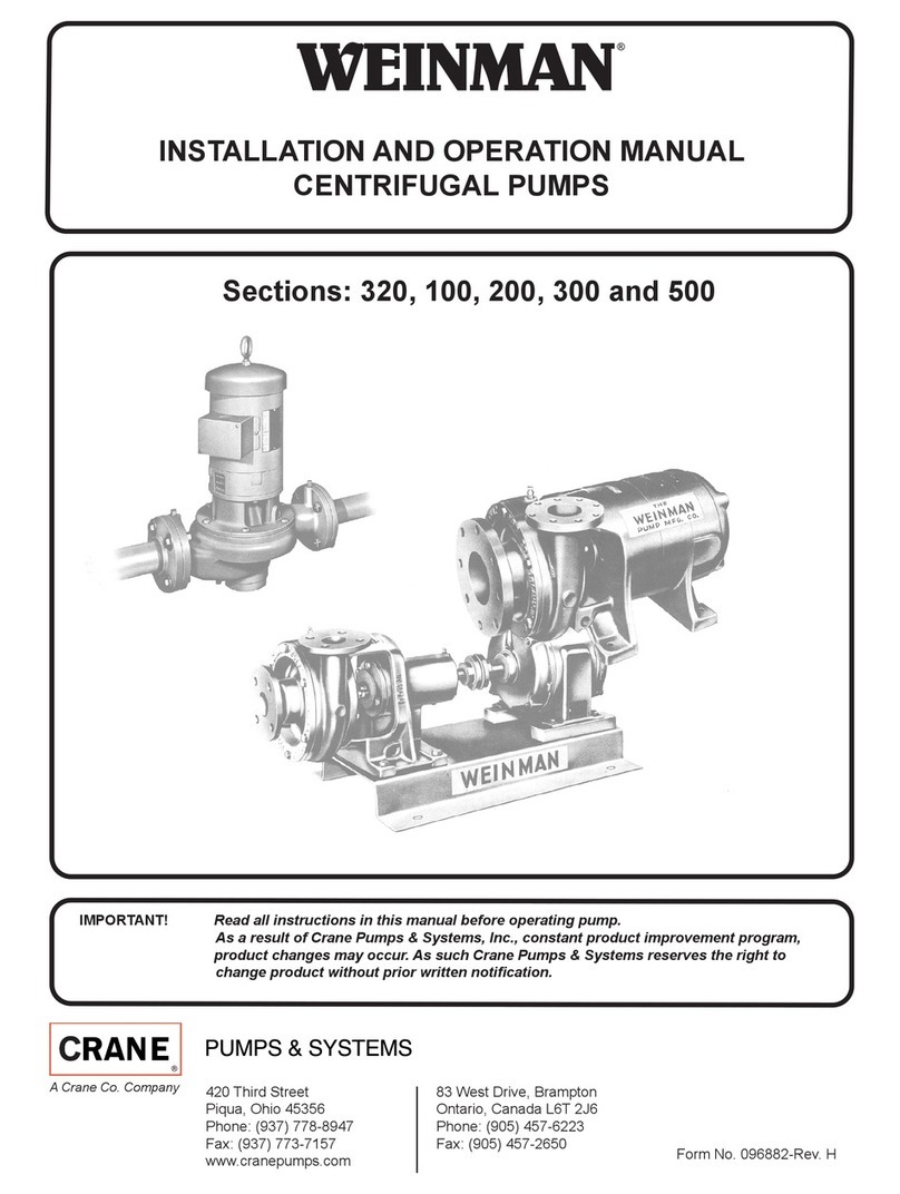
Crane WEINMAN 320 User manual

Crane

Crane WEINMAN 320 User manual

Crane Barnes 3SEH-L User manual

Crane

Crane Barnes 3SEH-L User manual

Crane Barnes 3SE3032L User manual

Crane

Crane Barnes 3SE3032L User manual

Crane BARNES 10XSHTB User manual

Crane

Crane BARNES 10XSHTB User manual

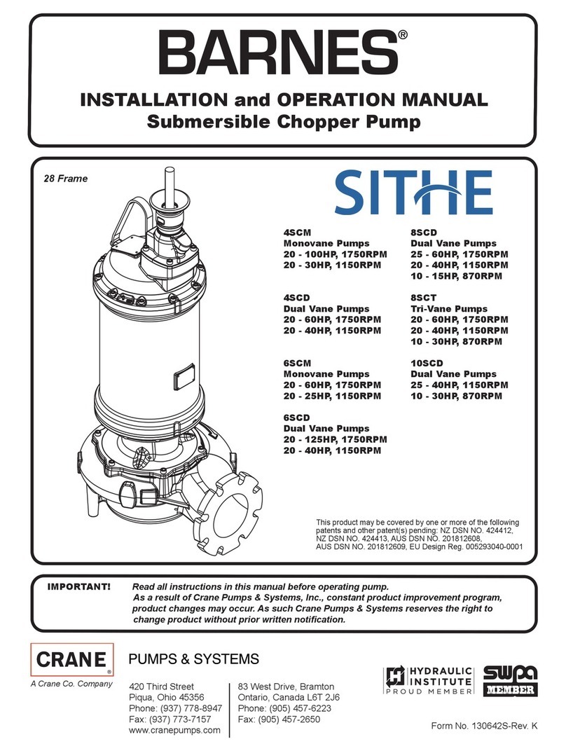
Crane Barnes SITHE 3XSCM User manual

Crane

Crane Barnes SITHE 3XSCM User manual

Crane Deming BAF-8 User manual

Crane

Crane Deming BAF-8 User manual

Crane PROSSER SED Series User manual

Crane

Crane PROSSER SED Series User manual

Crane DEMING 7365N Series User manual

Crane

Crane DEMING 7365N Series User manual

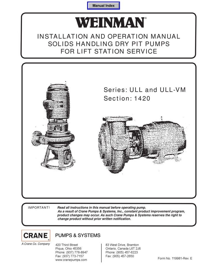
Crane Weinman ULL Series User manual

Crane

Crane Weinman ULL Series User manual

Crane BARNES 4SE-L Series User manual

Crane

Crane BARNES 4SE-L Series User manual

Crane Barnes SGV Series User manual

Crane

Crane Barnes SGV Series User manual

Crane BARNES 4030HCU User manual

Crane

Crane BARNES 4030HCU User manual

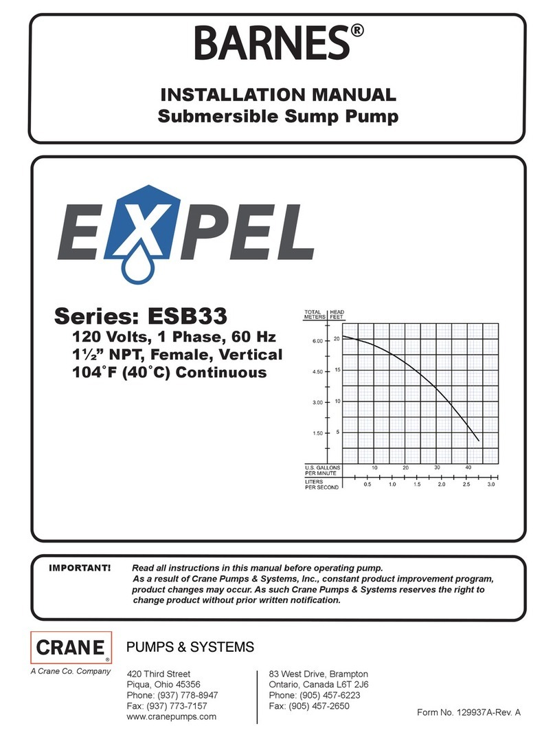
Crane BARNES ESB33 Series User manual

Crane

Crane BARNES ESB33 Series User manual

Crane DEMING 4507 Series Instruction manual

Crane

Crane DEMING 4507 Series Instruction manual

Crane OGP2022CO Series User manual

Crane

Crane OGP2022CO Series User manual

Crane Barnes SGV 2 HP User manual

Crane

Crane Barnes SGV 2 HP User manual

Crane Barnes SE51 Series User manual

Crane

Crane Barnes SE51 Series User manual

Crane BARNES RIVAL RV101A User manual

Crane

Crane BARNES RIVAL RV101A User manual

Crane DEMING 7365 Series User manual

Crane

Crane DEMING 7365 Series User manual

Crane Barnes EcoTRAN User manual

Crane

Crane Barnes EcoTRAN User manual

Crane PROSSER HYMERGIBLE 7-06000 Series User manual

Crane

Crane PROSSER HYMERGIBLE 7-06000 Series User manual

Popular Water Pump manuals by other brands

YATO YT-24800 Original instructions

YATO

YATO YT-24800 Original instructions

KSB EtaLine Pro Series Installation and operating manual

KSB

KSB EtaLine Pro Series Installation and operating manual

Watts HKF 8180 operating instructions

Watts

Watts HKF 8180 operating instructions

WITA Delta Midi 40 Series TRANSLATION OF THE ORIGINAL INSTALLATION AND OPERATING INSTRUCTIONS

WITA

WITA Delta Midi 40 Series TRANSLATION OF THE ORIGINAL INSTALLATION AND OPERATING INSTRUCTIONS

PondMAX PV350L instruction manual

PondMAX

PondMAX PV350L instruction manual

Grundfos MAGNA 32-60 instructions

Grundfos

Grundfos MAGNA 32-60 instructions

Nordson Prodigy Generation II product manual

Nordson

Nordson Prodigy Generation II product manual

Desmi NSA Series Operation and maintenance instructions

Desmi

Desmi NSA Series Operation and maintenance instructions

Zoeller BASEMENT SENTRY STBC301 manual

Zoeller

Zoeller BASEMENT SENTRY STBC301 manual

Pentair STA-RITE MS Series owner's manual

Pentair

Pentair STA-RITE MS Series owner's manual

Stuart Turner techflo qt Installation, operation & maintenance instructions

Stuart Turner

Stuart Turner techflo qt Installation, operation & maintenance instructions

Hydromatic HV200 Series manual

Hydromatic

Hydromatic HV200 Series manual

Soleus Air SG-DEH-PEX operating instructions

Soleus Air

Soleus Air SG-DEH-PEX operating instructions

BUSCH COBRA BC 0100 F Installation and maintenance instructions

BUSCH

BUSCH COBRA BC 0100 F Installation and maintenance instructions

YAMADA DP-Fs Series Maintenance manual

YAMADA

YAMADA DP-Fs Series Maintenance manual

EBARA 3TP installation manual

EBARA

EBARA 3TP installation manual

Server 100239 quick start guide

Server

Server 100239 quick start guide

Ingersoll-Rand 650883-XXX-B Operator's manual

Ingersoll-Rand

Ingersoll-Rand 650883-XXX-B Operator's manual

manuals.online logo
manuals.online logoBrands
  • About & Mission
  • Contact us
  • Privacy Policy
  • Terms and Conditions

Copyright 2025 Manuals.Online. All Rights Reserved.