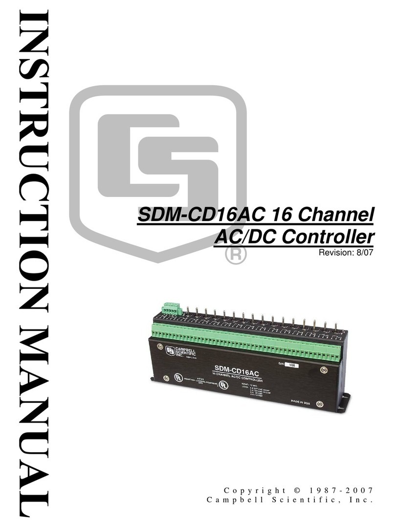
TGW CRUZcontrol Instruction manual

INSTALLATION,OPERATION,MAINTENANCE
MANUAL
CRUZcontrol®
For NBA®and XP43
IOM P\N: 90480009
Revision Date: March 18, 2019

IOM CRUZcontrol®
P/N: 90480009 Revision Date: 03/18/2019 Page 2of 58
Index
Purpose ................................................................................................................................................. 3
CRUZcontrol Logic Assembly ................................................................................................................ 5
Basic Logic ............................................................................................................................................ 6
Progressive Logic .................................................................................................................................. 7
Logic Assembly Specifications............................................................................................................... 9
Logic Module Wiring ............................................................................................................................ 10
CRUZcontrol On Site Installation ......................................................................................................... 11
NBA®23 to RLC®25 CRUZcontrol Installation..................................................................................... 12
Power Supply Requirements................................................................................................................ 14
Power Supply Wiring ........................................................................................................................... 16
Generation 2 Function Modules ........................................................................................................... 19
Use of 115 VAC controls with all Function Modules ............................................................................. 21
Full Function Module 1138074............................................................................................................. 22
Release Function Module E0006305 ................................................................................................... 30
Zone Status Function Module E0006306 ............................................................................................. 36
Logic Truth Tables ............................................................................................................................... 39
Generation 2 Function Modules - Definitions ....................................................................................... 41
Warnings and Cautions........................................................................................................................ 41
Discharge Logic Assembly................................................................................................................... 42
NBA®23 Brake Control......................................................................................................................... 43
Auxiliary Photoelectric Sensors............................................................................................................ 43
Reflectors ............................................................................................................................................ 44
Sensor Valve Assemblies .................................................................................................................... 44
Extension Cables................................................................................................................................. 44
TGW Systems Controls Guidelines See following pages. .................................................................... 45
TGW-ERMANCO Controls Guidelines ................................................................................................. 45
Cutler-Hammer Cut Sheet – IM08302001E Rev 02 ............................................................................. 56
Cutler-Hammer Cut Sheet – P50244 Rev 02 ....................................................................................... 56
TGW General Information.................................................................................................................... 57
History ................................................................................................................................................. 57
TGW Systems Information................................................................................................................... 58

IOM CRUZcontrol®
P/N: 90480009 Revision Date: 03/18/2019 Page 3of 58
Purpose
It is the intent of TGW Systems, through this
manual, to provide information that acts as a
guide in the installation, operation and
maintenance of TGW Systems conveyors
featuring CRUZcontrol Logic.
This manual describes basic installation
practices, assembly arrangements, preventive
maintenance and assists in replacement parts
identification.
This service manual is intended for use by
personnel who are knowledgeable of installation
and safe working practices on conveyor
systems.
Not all applications and conditions can be
covered; therefore, this manual is to be used as
a guide only.
If additional copies of this manual are needed or
if you have any question concerning the
conveyor please contact your Business Partner
or TGW Systems' Customer Support at 231-798-
4547 or www.tgw-conveyor.com.

IOM CRUZcontrol®
P/N: 90480009 Revision Date: 03/18/2019 Page 4of 58
TGW Systems Policies
TGW Systems Equipment Warranty
TGW Systems warrants that the material and workmanship
entering into its equipment is merchantable and will be
furnished in accordance with the specifications stated.
TGW Systems agrees to furnish the purchaser without charge
any part proved defective within 2 years from date of
shipment provided t
he purchaser gives TGW Systems
immediate notice in writing and examination proves the claim
that such materials or parts were defective when furnished.
For drive components specific to XenoROL® (i.e. Xeno belts,
slave Xeno belts, drive spools, standard and speed-up, and
spacers), this warranty shall be extended to five years of
running use, provided the conveyors are applied, installed
and maintained in accordance with TGW Systems published
standards. Other than the above, there are no warranties
which exte
nd beyond the description on the face hereof.
Consequential damages of any sort are wholly excluded.
The liability of TGW Systems will be limited to the
replacement cost of any defective part. All freight and
installation costs relative to any warranted part will be at the
expense of the purchaser. Any liability of TGW Systems
under the warranties specified above is conditioned upon the
equipment being installed, handled, operated, and
maintained in accordance with the written instructions
provided or approved in writing by TGW Systems.
The warranties specified above do not cover, and TGW
Systems makes no warranties which extend to, damage to
the equipment due to deterioration or wear occasioned by
chemicals, abrasion, corrosion or erosion; Purchaser's
misapplication, abuse, alteration, operation or maintenance;
abnormal conditions of temperature or dirt; or operation of the
equipment above rated capacities or in an otherwise improper
manner.
THERE ARE NO WARRANTIES, EXPRESSED OR
IMPLIED, INCLUDING, BUT NOT
LIMITED TO,
WARRANTIES OF MERCHANTABILITY OR FITNESS FOR
A PARTICULAR PURPOSE, EXTENDING BEYOND THOSE
SET FORTH IN THIS STATEMENT OF WARRANTY.
Rev 03/01/2019
TGW Environment Standards
TGW equipment is designed to be installed in a
clean, dry warehouse environment. Exposure to
extreme humidly, direct sunlight, blowing dirt or
rain can permanently damage some components
of TGW conveyor. In particular, the curing agents
in concrete are known to attack and degrade the
urethane conveyor components.
When installing conveyor on a new construction
site, be sure that the concrete is properly cured
before setting conveyor on it. In addition, if
conveyors are stored in the proximity of curing
concrete, proper ventilation must be used to direct
the curing agent fumes away from the conveyor.
Failure to comply with these guidelines will void
the TGW warranty on any failed components that
result from these environment issues.
03/01/2019

IOM CRUZcontrol®
P/N: 90480009 Revision Date: 03/18/2019 Page 5of 58
CRUZcontrol Logic Assembly
The CRUZcontrol Logic Assembly consists of a polarized retro-reflective type photoelectric sensor,
pneumatic valve and logic module integrated into one assembly.
The photoelectric sensor will function reliably on conveyor widths up to 34 inches between frames. The
sensor is polarized, and is not affected by shiny surfaces. On NBA®23 applications, the reflector is
mounted with a 6 inch offset from the photoelectric sensor, so that the sensor scans across the conveyor
on a slight angle.
The sensor bracket as provided allows for easy adjustment of the sensor. An LED function indicator on
the back of the sensor aids in the adjustment of the sensor. The LED is off if the sensor is not aligned,
flashes if functional but marginally aligned, and is on steady if properly aligned.
The pneumatic valve operates at a range of 0-116 psi, with a flow rate of Cv = 0.100 US Gallons/min.
Observe the operating pressure requirements of the conveyor. For example, NBA™ conveyor should
never be operated at greater than 14 psi.)
There are four different CRUZcontrol Logic Assemblies:
TGW Systems Part No. CRUZcontrol Logic Assemblies – Description
E0001900A Basic Logic, XenoROL®
E0001901A Basic Logic, NBA 23
E0001904A Progressive Logic, XenoROL
E0001905A Progressive Logic, NBA 23
The NBA CRUZcontrol Logic Assembly provides an “air to drive” logic output utilizing a normally closed
pneumatic valve. The XenoROL CRUZcontrol Logic Assembly provides an “air to brake” logic output,
utilizing a normally open pneumatic valve. With both types of logic, the pneumatic valve is energized for
a zone to be running.
Each version of CRUZcontrol also comes as either Basic Logic or Progressive Logic. The following
describes the differences between the two logic alternatives. The descriptions as written more closely
describe product movement on a XenoROL based accumulation conveyor, where accumulated product
is actually brought to a full stop. NBA 23 conveyor, where a stopped zone isn’t usually braked but
becomes gravity flow, will have very different product flow characteristics. The coasting of product
through gravity zones will result in gaps closing up, and could yield higher throughput rates regardless of
the type of logic selected.

IOM CRUZcontrol®
P/N: 90480009 Revision Date: 03/18/2019 Page 6of 58
Basic Logic
Basic Logic functions such that when any two successive photoelectric sensors are blocked, the second
zone upstream is set to accumulate. In the above example, the discharge zone, Zone 1, is shown
stopped, signifying that release from the zone is being inhibited and the Zone 1 sensor is blocked. Zone
1 sensor blocked and Zone 2 sensor blocked results in Zone 2 being stopped. Zone 3 and Zone 4
sensors are not blocked, and the zones are running. Zone 5 sensor is blocked, but the zone is running
because the Zone 4 sensor is not blocked. Zone 6 is stopped because both Zone 5 and Zone 6 sensors
are blocked.
Note that with Basic Logic products being transported on the conveyor are separated by a gap of at least
one zone length. This will reduce the transportation throughput capacity of the conveyor. The rate at
which product is introduced onto an accumulation conveyor of this type must not exceed the
transportation capacity of the conveyor.
Discharge from Basic Logic
A Singulation Release signal given to the Zone 1 Logic Assembly releases product from that zone. As
released product clears a photoelectric sensor, the product stopped at the next upstream zone is
released. This will create a one-zone length gap between all released products, assuming conveyor
speeds (accumulation conveyor and downstream conveyor) are identical.
If the line is set to Slug Release (Train Release), all affected zones will run, resulting in the release of
product with little or no gaps. This overrides the normal Basic Logic function.
All product movement as described for transportation, accumulation, and discharge is based on zone
lengths, meaning only one product is in each zone. If more than one product should occupy a single
zone, which could occur with small products, they will usually move together or stop together, or they
could eventually become separated into different zones. This is true for both Basic Logic and Progressive
Logic.
Zone 5
Stopped
Zone 6
Running
Zone 4
Stopped
Zone 3
Stopped
Zone 2
Stopped
Zone 1
Running
Flow
Flow
Conveyor
Running
Flow
Conveyor
Stopped
Zone 1
Stopped
Zone 2
Stopped
Zone 3
Running
Zone 4
Running
Zone 5
Running
Zone 6
Stopped

IOM CRUZcontrol®
P/N: 90480009 Revision Date: 03/18/2019 Page 7of 58
Progressive Logic
Progressive Logic functions such that no zones are set to accumulate unless all downstream zones hold
accumulated product and the photoelectric sensors are blocked. In the above example, the discharge
zone, Zone 1, is shown stopped which is a result of the release from the zone being inhibited and the
Zone 1 sensor being blocked. Zone 2 sensor not being blocked results in all upstream zones, Zone 2
through Zone 6, running.
Note that with Progressive Logic products being transported on the conveyor can remain tightly packed,
without any gaps being created.
Discharge from Progressive Logic
A Singulation Release signal given to the Zone 1 Logic Assembly releases product from that zone. Each
successive upstream zone will also begin releasing product, but with a two tenths of a second release
delay from each zone to the next upstream zone. This will create a small gap between released products,
depending on product sizes, the number of products occupying each accumulation zone, and the
conveyor speed.
If the line is set to Slug Release (Train Release), all affected zones will run, resulting in the release of
product with little or no gaps. This overrides the normal Progressive Logic function. The two tenths of a
second release delay between zones does not occur with Slug Release.
Zone 5
Delayed
Zone 6
Delayed
Zone 4
Delayed
Zone 3
Delayed
Zone 2
Running
Zone 1
Running
Flow
Flow
Conveyor
Running
Flow
Conveyor
Stopped
Zone 1
Stopped
Zone 2
Running
Zone 3
Running
Zone 4
Running
Zone 5
Running
Zone 6
Running

IOM CRUZcontrol®
P/N: 90480009 Revision Date: 03/18/2019 Page 8of 58
Cautions
CRUZcontrol Logic Assemblies are designed to be fail-safe. A loss of module power, a disconnected or
severed cable, or a dirty or failed photoelectric sensor will all result in the stopping of a zone, initiating
accumulation beginning from the affected zone.
With Progressive Logic, failure of a Logic Assembly to function properly could possibly result in product
accumulating with zones not stopping as required. While this should be unlikely due to the fail-safe
nature of the Logic Assembly, a product jam preventing product from blocking a zone sensor would also
result in a zone not functioning. The effects of such a failure should be considered. This type of failure
could result in excessive line pressure, eventually causing product to push through the discharge zone
of the conveyor. If needed, jam detection sensors could be used to minimize the effects of such a failure.
Progressive Logic NBA®23 should normally be specified with one Basic Logic Assembly at the discharge
end of every 12-foot bed of conveyor. This limits the length of conveyor that could possibly be driving
product against a jam point to less than 12 feet. The use of one Basic Logic Assembly on every 12-foot
bed will disrupt the flow of product to some degree, but with adequate speed and product weight the
flowing product should coast through the basic zones without any appreciable effect on the throughput
rate. One exception is at the charge and discharge ends of a length of NBA 23, where the effects of
using Basic Logic Assemblies on the throughput rate needs to be considered. If there is a need to
maximize throughput rates, the use of all Progressive Logic Assemblies should be retained, but only in
those locations.
CRUZcontrol provides the ability to for slug release. If the line is set to Slug Release, all affected zones
will run immediately, regardless of downstream conditions, resulting in the immediate release of product
with little or no gaps. Both the Basic and Progressive Logic Assemblies release at the maximum possible
discharge rate when slug release is enabled. Slug release does create a situation where a product jam
will result in excessive line pressure buildup. If the slug release feature is used, it should be used with
caution, and for a limited number of successive accumulation zones.
Configuration Options
Basic Logic Assemblies and Progressive Logic Assemblies can be intermixed. An example of where this
would be advantageous would be the placing of one Basic Logic conveyor bed at the end of a long length
of Progressive Logic conveyor. The Progressive Logic would allow the conveyor to receive and transport
product at higher throughput rates, while the Basic Logic discharge section would singulate product being
released.

IOM CRUZcontrol®
P/N: 90480009 Revision Date: 03/18/2019 Page 9of 58
Logic Assembly Specifications
Photoelectric Sensor:
Sensing Mode
Reflex
Light Source
Red LED
Status Indicator
Red
Life Expectancy
100,000h @ 77°F
Cable length
28 inches from logic module to sensor
Connection to logic module
Hard-wired
Ambient Temperature - Operating
14…130°F
Ambient Temperature - Storage
-13…122°F
Logic Module:
Cable Length
42 inches logic module to end of connector
Enclosure Rating
IP42
Housing Material
ABS plastic
Supply Voltage
24 VDC (-20% / +15%)
Current Consumption
67mA (includes logic module, MH sensor, &
valve)
Response Time
<2.5ms
Connection
M12 4-pin Single Key
Pneumatic Valve:
Operating Pressure Range
0-116 psi (0-8 bar)
Ventilation capacity
Qn = 100 Nl/min, Cv = 0.100 USGallon/min
Input Air Connection*
3/8 in. straight quick connects
Output Air Connection
¼ in. straight quick connect
Operating Mode
N.O. or N.C. (two models)
The pneumatic valve has a small red lever controlling valve shutoff. This must be set to “0” (not “1”) for
proper valve operation.
For zone lengths greater than 36 inches, the following extension cable is used to connect to each Logic
Assemblies. These are provided pre-installed on the conveyor with the other CRUZcontrol components:
TGW Systems Part No.
Description
RK4.4T1RS4.4T Extension Cable (39 inches)

IOM CRUZcontrol®
P/N: 90480009 Revision Date: 03/18/2019 Page 10 of 58
Logic Module Wiring
Installation
CRUZcontrol will come pre-installed on the conveyor:
•The CRUZcontrol Logic Assemblies are installed into the side channel of the conveyor
bed.
•The air supply for the conveyor is plumbed the length of the conveyor bed, passing through
each Logic Assembly, and provided with push-in quick connectors at the ends of the
conveyor bed.
•The zone control air is plumbed from the Logic Assembly to the zone air pucks or cylinders.
•The photoelectric sensors are mounted for each zone, along with the reflector across the
conveyor bed. The photoelectric sensors are tested to insure proper alignment with the
reflectors, as well as proper functioning of the Logic Assemblies.

IOM CRUZcontrol®
P/N: 90480009 Revision Date: 03/18/2019 Page 11 of 58
Conveyor Flow
(Some conveyor configurations will result in the conveyor flow direction being reverse from what
is shown in the illustration. In those situations, the Interconnection Cables are routed in reverse
from that shown.)
CRUZcontrol On Site Installation
Installation will consist of the following:
•Connection of Air Supply air tubing between conveyor beds, closing and terminating the
ends of the Air Supply tubing, and providing the air supply to the conveyor.
•Connection of the Logic Assembly interconnection cables from the last zone of a conveyor
bed to the first zone in the next upstream conveyor bed.
•Providing a suitable 24 VDC power supply and connecting it into the string of Logic
Assemblies.
•Providing a Singulation Release signal for the discharge zone (using Function Module).
•Providing a Slug Release signal for the discharge zone, if required (using Function
Module).
•Obtaining Zone Status indications as required for system control (using Function Module).
•Terminating unconnected M12 cable ends with Termination Plugs. This is suggested to
protect the cable ends from damage.
•Adding auxiliary photoelectric sensors as required for discharge and full line condition
sensing.
TGW Systems Part No. Description
90139992 Male M12 Termination Plug (use for terminating male cable
ends)
90139994 Female M12 Termination Plug (use for terminating female
cable ends)
Photoelectric
Sensor
Logic
Module
Air Supply
Air Supply
Zone Control
Air
Zone Control
Air
Logic Assembly
Interconnection Cable from
downstream zone
(Shown disconnected from
Logic Module Assembly)
Logic Assembly
Interconnection
Cable to upstream
zone.

IOM CRUZcontrol®
P/N: 90480009 Revision Date: 03/18/2019 Page 12 of 58
NBA®23 to RLC®25 CRUZcontrol Installation
The accumulating option on your RLC 25 curve simply solves all previous problems associated with V-
belt driven curves. IT IS NOT NECESSARY TO CLEAR THE CURVE OF PRODUCT when accumulation
reaches it. There is no lost accumulation space since THE CURVE IS AN EXTENSION OF THE
FOLLOWING ACCUMULATION. When the zone following the curve accumulates, so does the curve.
THERE ARE NO CONTROLS YOU NEED TO SUPPLY.
No “full-line” photoeye is required following the curve. No special gaps need to be forced between
products entering the curve. THERE IS NO INDEXING OR OTHER DEVICES, MOTORS, CONTROLS
OR WIRING that need to be engineered or installed.
NOTE
A roller brake is recommended at the discharge end of any NBA®23 accumulation conveyor preceding
the curve, to prevent coasting products from impacting those in the curve.
The examples on the following page show plumbing for several possible configurations of the
accumulating option of the RLC 25 product line. Note that Example “C” illustrates the upstream NBA 23
beds with typical plumbing and controls shown.

IOM CRUZcontrol®
P/N: 90480009 Revision Date: 03/18/2019 Page 13 of 58
1ST CURVE INTERMEDIATE BED 2ND CURVE
1ST CURVE 2ND CURVE
1ST CURVE INTERMEDIATE BED
EXAMPLE "C"
EXAMPLE "B"
EXAMPLE "A"
EXAMPLE OF
UPSTREAM NBA

IOM CRUZcontrol®
P/N: 90480009 Revision Date: 03/18/2019 Page 14 of 58
Power Supply Requirements
CRUZcontrol operates from a nominal supply voltage of 24 volts DC. The wiring methods and
componentry used are such that a Class 2 power supply should be used. This limits the output power to
a total of 100 VA. The current required for each CRUZcontrol Logic Assembly is 67mA, which allows for
up to 53 zones per power supply. There is also a limit on the maximum number of Logic Assemblies that
can be in one continuous string, based on the cable length from the power supply to the first Logic
Assembly:
More than one string of Logic Assemblies can be connected to a power supply, up to the maximum of 53
zones.
Power Supplies
The following power supplies are available from TGW Systems. Technical specifications for each are
included with this manual.
TGW Systems Part No. Description
1101825 100-250 VAC input Power Supply Kit including T cable and
Mounting Bracket. (reference Cutler-Hammer # PS256A-
01B1)
94510092 342-528 VAC 3 phase input Power Supply Kit including a T
cable and a Mounting Bracket. (reference C-H # PS256A-
44B1)
Cable length –
power supply to first Logic Module
Assembly
3 ft 9 ft 13 ft
Maximum # of Logic Module Assemblies per string 33 32 31
Maximum # based on zones greater than 36 inches 24 23 23

IOM CRUZcontrol®
P/N: 90480009 Revision Date: 03/18/2019 Page 15 of 58
Some things to consider regarding the use of these power supplies:
100-250 VAC input Power Supply:
•The output voltage, while rated at 27 VDC, is suitable for use with CRUZcontrol.
•A T Cable is provided with the Power Supply Kit for connection to the Power Supply output
terminals.
•There are two sets of output terminals. These are connected in parallel, and provided only as a
convenience for the connection of two separate output cables. The T Cable can be connected to
either of these sets of terminals.
•The Release In terminals, when provided with a voltage input signal, will put out a 24 VDC level
signal which can be used to enable (provide power to) either the Logic Signal or Slug Signal lines
of CRUZcontrol. The Release Out switch should be set to Sourcing. (The Release Out feature
is not required to operate CRUZcontrol. These same functions are also provided for with the
Function Module, which comes with plug in connections.)
•The Power Monitor contact output provides a contact closure indication of 24 VDC power output
being on. This is not required to operate CRUZcontrol.
342-528 VAC 3 phase input Power Supply:
•This power supply can be connected into the motor wiring for the conveyor, eliminating the need
to run a separate power feed to the power supply. The connections should be made at the output
terminals of the motor safety switch (disconnect switch). The effect of the power supply load on
the motor overload setting, while minimal, does need to be considered.
•The Three Phase AC Out terminals allow for the connection of a second power supply, if more
than one is required.
•The output voltage, while rated at 26VDC, is suitable for use with CRUZcontrol.
•A T Cable is provided with the Power Supply Kit for connection to the Power Supply output
terminals.

IOM CRUZcontrol®
P/N: 90480009 Revision Date: 03/18/2019 Page 16 of 58
Power Supply Wiring
Connection made between two Logic Assemblies using a T Cable:
This drawing illustrates a power connection made between two intermediate accumulation zones making
use of a T Cable. Note that all power and control signals, including the Slug and Logic Signals, pass
through the T Cable uninterrupted.
T CABLE
CONVEYOR FLOW
24 VDC POWER SUPPLY
24v
+24 VDC (Brown)
0 VDC (Blue)
+
-

IOM CRUZcontrol®
P/N: 90480009 Revision Date: 03/18/2019 Page 17 of 58
One Power Supply used to power two separate CRUZcontrol sections:
This drawing illustrates the use of one power supply to power two separate, short CRUZcontrol sections
on two different conveyors. This can be done to make better use of the full capacity of a power supply,
provided that the total number of Logic Assemblies doesn’t exceed 53. The number of CRUZcontrol
zones that can be connected per string must also be reduced according to the total length of wire and
cable used to reach the first CRUZcontrol Logic Assembly of the string (refer to chart under Power Supply
Requirements section).
TGW Systems Part Number Description
224-201 Connectors
PS256ADAPT44B3
T Cable (one is already provided with Power
Supply Kits)
+
-
+24 VDC (Brown)
0 VDC (Blue)
24 VDC POWER
SUPPLY
24v
Conveyor 1
CRUZcontrol
circuit
Conveyor 2
CRUZcontrol
circui
t
T CABLE
14 AWG WIRE
CONNECTORS
CONVEYOR FLOW

IOM CRUZcontrol®
P/N: 90480009 Revision Date: 03/18/2019 Page 18 of 58
Using two Power Supplies to power one extended CRUZcontrol string:
A CRUZcontrol string with more than 53 Logic Assemblies would require the use of more than one power
supply. This can be done, but it requires that the power supplies be isolated from each other at the +24
volt line. This drawing illustrates how to isolate the two strings making use of a Power Interrupt Cable.
The + VDC line, (pin 1), is not passed through, while the Slug Release and Singulation Release Signals
as well as DC common (0 vdc) are connected so as to pass the signals through uninterrupted.
TGW Systems Part Number Description
ZPI-P1 Power Interrupt Cable, 8 inches long
Last CRUZcontrol
Logic Assembly
powered fr
om Power
Supply 1
First CRUZcontrol
Logic Assemblies
powered from Power
Supply 2
POWER
INTERRUPT
CABLE
CONVEYOR FLOW

IOM CRUZcontrol®
P/N: 90480009 Revision Date: 03/18/2019 Page 19 of 58
Generation 2 Function Modules
Function Modules (Generation 2)
Function Modules are an important accessory to CRUZcontrol. They provide electrical isolation for
external processes and controls and facilitate CRUZcontrol system applications.
There are three different Function Modules, each providing different groups of functions:
These Function Modules replace the previous (Generation 1) 1138074 Function Module. The Release
Function Module, 1138075, should serve most application requirements.
A Function Module is shown connected to the most downstream or discharge Logic Assembly. One
cable from the Function Module does not need to be connected in this situation. A Function Module can
also be connected between Logic Assemblies or after the last Logic Assembly in the string.
TGW Systems Part Number Description
1138074 Full Function Module
1138075 Release Function Module
1138078 Zone Status Function Module

IOM CRUZcontrol®
P/N: 90480009 Revision Date: 03/18/2019 Page 20 of 58
Function Module Power Requirements
The Function Modules get power by being connected into a string of Logic Assemblies. As a result, it
will reduce the maximum number of Logic Assemblies that can be connected into one string. This is
shown in the following chart, which is based on a 3 foot cable from the power supply to the first Logic
Assembly, and 3 foot maximum zone spacing.
Number of Function Modules 0-2 3-7 8-12
Maximum # of Logic Module Assemblies per string 33 32 31
The Function Modules require 10mA of current at 24 VDC. This needs to be considered, as it will reduce
the total number of Logic Modules that can be connected to one Class 2 power supply to some quantity
less than 53.
Function Module Dimensions
Table of contents
Popular Controllers manuals by other brands
RIB
RIB K5 Operating and installation instructions
Altronix
Altronix PT724A Series installation guide
Flowserve
Flowserve Limitorque QX User instructions
elsner elektronik
elsner elektronik KNX eTR 205 Light Installation and adjustment
Hanna Instruments
Hanna Instruments HI 9931 instruction manual

SIYI
SIYI MK15 user manual
