THERMACUT EX-TRAFIRE 105HD User manual
EN Operating instructions
Plasma cutting power supply
CE - Version

EN - 2
EX-TRAFIRE®05HD
Table of contents
Identification ............................................................... EN-5
1.1 Marking.............................................................................................. EN-5
1.2 Identification plate ........................................................................... EN-5
1.3 Signs and symbols used.................................................................. EN-5
1. Classification of the warnings ......................................................... EN-6
2 Safety........................................................................... EN-6
2.1 Designated use................................................................................. EN-6
2.2 Obligations of the operator ............................................................ EN-7
2.3 Warning and notice signs................................................................ EN-7
2. Product-specific safety instructions................................................ EN-7
2.5 Safety instructions for the electrical power supply ...................... EN-8
2.6 Safety instructions for plasma cutting............................................ EN-8
2.7 Personal protective equipment ...................................................... EN-8
2.8 Emergency information................................................................... EN-8
3 Scope of delivery......................................................... EN-9
4 Product description ...................................................EN- 0
.1 Assembly and use .......................................................................... EN-10
.2 Technical data................................................................................. EN-11
.3 Technical data for cutting torches FHT-EX®105TTH and
FHT-EX®105TTM............................................................................. EN-12
5 Transport and positioning .........................................EN- 4
6 Commissioning..........................................................EN- 5
6.1 Connecting to the gas supply....................................................... EN-15
6.2 Connecting the work lead............................................................. EN-15
6.3 Connecting the power supply cable ........................................... EN-15
6. Connecting the cutting torch........................................................ EN-16
6.5 Establishing the power supply ..................................................... EN-16
6.6 Connecting the CNC interface ..................................................... EN-17
6.6.1 Setting the DIP switches ................................................................ EN-18
6.6.2 Enabling the external DC coil with an external power supply . EN-19
6.6.3 Enabling the external AC coil with an external power supply.. EN-19
6.6. Enabling the industrially insulated module with an
external power supply................................................................... EN-20
6.6.5 Installing the cutting torch's gear rack ........................................ EN-20
6.7 Installing consumables for the hand and machine
cutting torches................................................................................ EN-21
7 Operation of the power supply .................................EN-23
7.1 LCD description.............................................................................. EN-2
7.1.1 Making settings .............................................................................. EN-2
7.1.2 Selecting the cutting mode........................................................... EN-25
7.2 Switching on the device ................................................................ EN-25
7.3 Manual cutting process ................................................................. EN-26
7. Manual grid cutting, gouging, marking process........................ EN-26
7.5 Connecting the work lead with the workpiece clamp............... EN-26
7.6 Cutting............................................................................................. EN-27
7.7 Piercing............................................................................................ EN-28
7.8 Gouging .......................................................................................... EN-29
7.8.1 Table for FHT-EX®105TT material removal................................. EN-29

EX-TRAFIRE®05HD
EN - 3
7.9 Aligning FHT-EX®105TTM machine cutting torch...................... EN-30
7.10 Stopping the cutting process ....................................................... EN-30
8 Decommissioning ..................................................... EN-30
9 Maintenance and cleaning........................................ EN-3
9.1 Maintenance and cleaning intervals ............................................ EN-32
0 Faults and troubleshooting....................................... EN-33
Disassembly.............................................................. EN-37
2 Disposal .................................................................... EN-38
12.1 Disposal of materials...................................................................... EN-38
12.2 Disposal of consumables .............................................................. EN-38
12.3 Packaging ........................................................................................ EN-38
3 Warranty ................................................................... EN-39
4 Block diagram........................................................... EN-40
5 Accessories ............................................................... EN-40
6 FHT-EX®05TTH hand cutting torch unit................... EN-4
7 FHT-EX®05TTH consumables for hand cutting torch .........
EN-42
17.1 FHT-EX®105TTH consumables for hand
cutting torch 5–85 A..................................................................... EN- 2
17.2 FHT-EX®105TTH consumables for hand
cutting torch 100–105 A ................................................................ EN- 3
17.3 FHT-EX®105TTH consumables for SmoothLine hand
cutting torch.................................................................................... EN- 3
8 FHT-EX®05TTM machine cutting torch unit ............ EN-44
18.1 FHT-EX®105TTM machine cutting torch without gear rack....... EN-
18.2 FHT-EX®105TTSM short machine cutting torch ......................... EN-
9 FHT-EX®05TTM consumables for machine
cutting torch.............................................................. EN-46
19.1 FHT-EX®105TTM consumables for standard machine
cutting torch 5–85 A..................................................................... EN- 6
19.2 FHT-EX®105TTM consumables for standard machine
cutting torch 100–105 A ................................................................ EN- 7
19.3 FHT-EX®105TTM consumables for SmoothLine
machine cutting torch.................................................................... EN- 7
19. FHT-EX®105TTM consumables for marking machine
cutting torch.................................................................................... EN- 8
20 Ordering information on bulk packs and starter kits EN-49
2 Cutting tables for mechanical cutting....................... EN-50
21.1 5 A cutting, shielded, with compressed air .............................. EN-51
21.2 55A cutting, shielded, with compressed air ............................... EN-52
21.3 65A cutting, shielded, with compressed air ............................... EN-53

EN - 4
EX-TRAFIRE®05HD
21. 75A cutting, shielded, with compressed air ............................... EN-5
21.5 85A cutting, shielded, with compressed air ............................... EN-55
21.6 100–105 A cutting, shielded, with compressed air.................... EN-57
21.7 0– 5 A cutting, SmoothLine, shielded, with compressed air . EN-59
21.8 Tables for marking.......................................................................... EN-60
21.8.1Marking, shielded, with compressed air or argon ..................... EN-60
EX-TRAFIRE®05HD Identification
EN - 5
Identification
The EX-TRAFIRE®105HD is a mobile cutting power supply for mechanized
and manual plasma cutting, gouging, and marking. The
EX-TRAFIRE®105HD uses gas or nitrogen to cut almost all conductive
metals. The device may be operated only with original Thermacut® spare
parts. This documentation describes the EX-TRAFIRE®105HD cutting
power supply only.
When used in this documentation, the term “device” always refers to the
EX-TRAFIRE®105HD cutting power supply.
1.1 Marking
This product fulfills the requirements that apply to the market to which it
has been introduced. A corresponding marking has been affixed to the
product, if required.
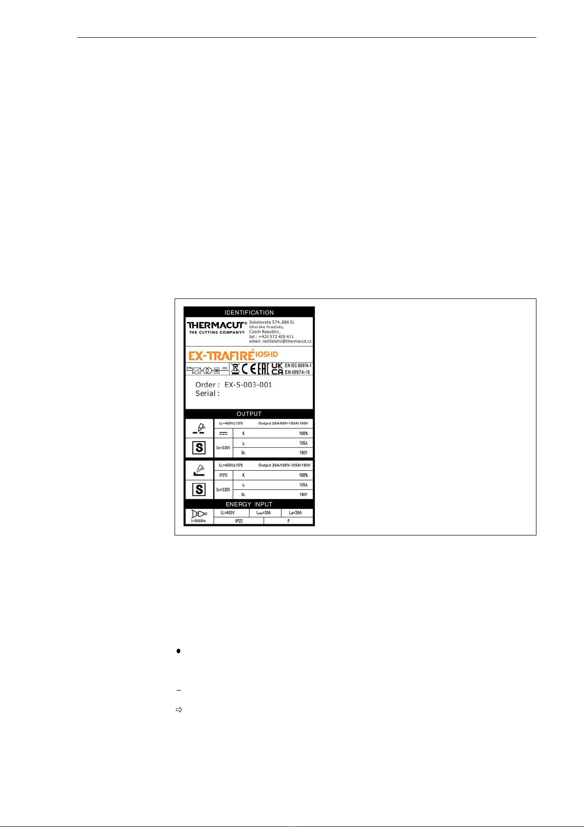
1.2 Identification plate
The device is labeled by means of an identification plate on the housing.
• For inquiries, please have at hand the device type, device number, and
year of construction per the identification plate.
1.3 Signs and symbols used
The following signs and symbols are used:
Fig. 1 EX-TRAFIRE®105HD identification plate
General instructions.
Action(s) to be carried out in succession.
Lists.
Cross-reference symbol refers to detailed, supplementary or further
information.
Caption, item description.
1
A

EN - 6
2 Safety EX-TRAFIRE®05HD
1.4 Classification of the arnings
The warnings are divided into four different categories and are indicated
prior to potentially dangerous work steps. The following signal words are
used depending on the type of hazard:
2 Safety
This chapter warns of residual hazards that should be kept in mind to
operate the product safely. Non-observance of the safety instructions may
result in risks to the life and health of personnel, and environmental
damage or material damage.
• Observe the document entitled “Safety Instructions”.
2.1 Designated use
The device described in this documentation may be used only for the
purpose and in the manner described. The device is used only for the
generation and control of the output current required for plasma cutting
and gouging. Any other use is considered improper. Unauthorized
modifications or changes to enhance the performance are not permitted.
• Do not exceed the maximum load data as defined by the
documentation supplied. Overloads lead to destruction.
• Do not make any constructive changes to this product.
• Do not use the device to thaw pipes.
• Do not use or store the device outdoors where it is wet.
DANGER
Describes an imminent threatening danger. If not avoided, it may cause
severe injuries or death.
WARNING
Describes a potentially dangerous situation. If not avoided, this may
result in death or serious injuries.
CAUTION
Describes a potentially harmful situation. If not avoided, this may result in
slight or minor injuries.
NOTICE
Describes the risk of impairing work results or material damage and
indicates irreparable damage to the device or equipment.

EX-TRAFIRE®05HD 2 Safety
EN - 7
2.2 Obligations of the operator
• Ensure that only qualified personnel are permitted to perform work on
the device or system.
Authorized personnel are:
— those who are familiar with the basic regulations on occupational
safety and accident prevention;
— those who have been instructed on how to handle the device;
— those who have read and understood these operating instructions;
— those who have been trained accordingly;
— those who are able to recognize possible risks because of their
special training, knowledge, and experience.
• Keep untrained persons out of the work area.
• Each time the devicor another authorized specialist perform a safety
inspection in accordance with DIN IEC 6097 Part : “Periodic
inspection and testing”.
The device can produce electromagnetic fields that could impact the
proper function of cardiac pacemakers and implanted defibrillators.
• Do not use the device if you have a pacemaker or an implanted
defibrillator.
This Class A cutting device is not intended for use in residential areas with
a public low-voltage power supply system. It can potentially be difficult to
guarantee electromagnetic compatibility in these areas due to both
conducted and emitted interference.
• The device may be used only in industrial zones according to
DIN EN 61000-6-3.
2.3 Warning and notice signs
The following warning, notice and mandatory signs can be found on the
product:
These markings must always be legible. They may not be covered,
obscured, painted over, or removed.
2.4 Product-specific safety instructions
• Do not use or store the device outdoors where it is wet.
• Do not operate the device if the housing is open.
• Read and observe the operating instructions.

EN - 8
2 Safety EX-TRAFIRE®05HD
2.5 Safety instructions for the electrical po er supply
• Ensure that the input power cable is not damaged, for example, by
being driven over, crushed or torn.
• Check the input power cable for damage and wear at regular intervals.
• If it is necessary to replace the input power cable, only models indicated
by the manufacturer may be used.
• Only a qualified electrician should carry out work on the input power
cable and the mains plug.
• Splash-water protection and mechanical stability must be ensured when
replacing the mains plug of the input power cable.
2.6 Safety instructions for plasma cutting
• Plasma cutting may cause damage to the eyes, skin, and hearing. Note
that other hazards may arise when the device is used with other cutting
components. Therefore, always wear the prescribed personal protective
equipment as defined by local regulations.
• All metal vapors, especially lead, cadmium, copper, and beryllium, are
harmful. Ensure sufficient ventilation or extraction. Do not exceed the
current occupational exposure limits (OEL).
• To prevent the formation of phosgene gas, rinse workpieces that have
been degreased with chlorinated solvents using clean water. Do not
place degreasing baths containing chlorine in the vicinity of the cutting
area.
• Adhere to the general fire protection regulations and remove
flammable materials from the vicinity of the cutting work area prior to
starting work. Provide appropriate fire extinguishing equipment in the
workplace.
2.7 Personal protective equipment
• Wear your personal protective equipment (PPE).
• Ensure that others in close proximity are also wearing personal
protective equipment.
Personal protective equipment consists of protective clothing, safety
goggles, face protection, ear protectors, protective gloves, and safety
shoes.
2.8 Emergency information
• In the event of an emergency, immediately disconnect the following
supplies:
— Electrical power supply
— Gas supply

EX-TRAFIRE®05HD 3 Scope of delivery
EN - 9
3 Scope of delivery
The following components are included in the scope of supply:
— 1× EX-TRAFIRE®105HD cutting power supply
— 1× FHT-EX®105TTH or FHT-EX®105TTM cutting torch
— 1× work lead incl. workpiece clamp
— 1× operating instructions
— 1× “Safety Instructions” document
— 1× “Warranty” document
— 1× operating instructions for the cutting torch
— 1× starter kit
• Order the equipment parts and separately.
• The order data and ID numbers for the equipment parts and can be
found in the current product catalog.
• For more information about points of contact, consultation, and orders,
visit
www.thermacut.com
.
Although the items delivered are carefully checked and packaged, it is not
possible to fully rule out the risk of transport damage.
Goods-in inspection
• Check for order completeness by checking the delivery note.
• Check the delivered goods for damage (visual inspection).
Claim process
• If goods are damaged, contact the final carrier.
• Keep the packaging for possible checks by the carrier.
Returns
• Use original packaging and packing material for returns.
• If you have questions concerning the packaging or how to secure the
device, contact your supplier, carrier or transport company.
EN - 10
4 Product description EX-TRAFIRE®05HD
4 Product description
4.1 Assembly and use
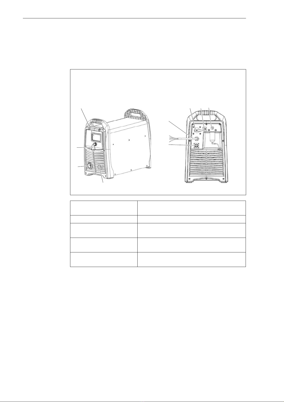
The control elements are located on the control panel. The connections are
on the front and rear of the device.
Fig. 2 Control elements and connections
ADisplay
B<POWER> switch
COptional BUS interface
DG1/ " gas connection, plug
EOptional CNC interface
FPower cable
GWork clamp connection
HTorch connection system (TCS)
IMulti-function button
Digital display (A) Displays the device status. A fault code is
displayed if a malfunction occurs.
<POWER> switch (B) Used to switch the device on and off.
BUS interface (C) For connecting the optional CAN BUS or
RS 85/ 22 BUS.
CNC interface
connection (E)
This interface is used to connect the device
with a CNC cutting table or robot.
Multi-function button (I) For toggling between two menus and
setting the cutting parameters.
D
I
C
B
A
F
E
G
H
EX-TRAFIRE®05HD 4 Product description
EN - 11
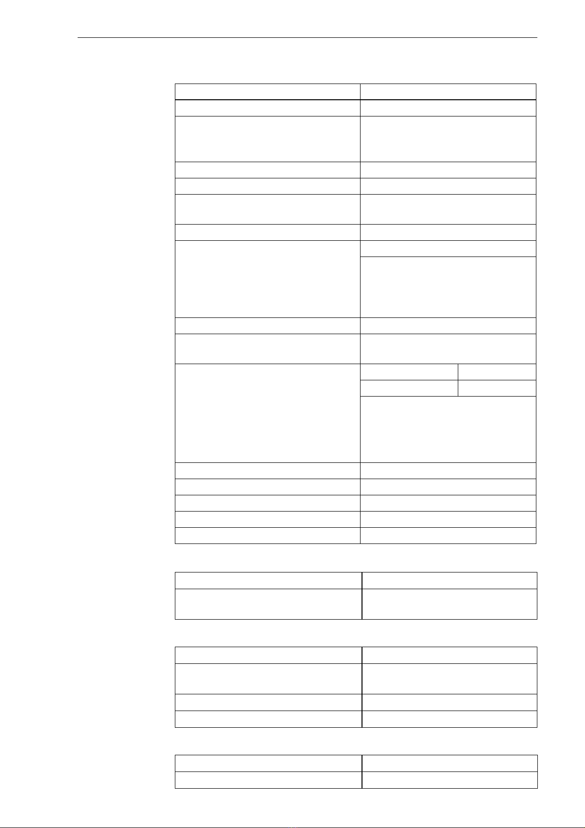
4.2 Technical data
Tab. 1 Power supply specifications
CE
Idle voltage (U0)330 V DC
Characteristic curve*
* The curve is defined as output
voltage versus output current
Declining
Output current (I2)20–105 A
Nominal voltage (U2)180 V DC
Output current at 00% duty
cycle (I2)
105 A
Maximum power input 27.5 kVA
Duty cycle (X*) a 40°C under
nominal conditions (U , I , U2, I2)
*X = tone/Tbase,
Tone = time, minutes
Tbase = 10 minutes
U1rms
100%
Ambient temperature −10°C to + 0°C
Input voltage (U )00 V AC ± 15%
3 PH/50–60 Hz
Rated input current (I1rms) and
effective input current (I1eff) at rated
output voltage (U2) and rated
output current (I2) – only for cutting
mode.
eff = effective
rms = root mean square
I1rms I1eff
39 A 39 A
Complies with standards
IEC 6097 -1,
IEC 6097 -10
Insulation class F
Protection type IP23S
Tilt angle (with or without wheels) Up to 15°
Dimensions (L × H × W) [mm]613 × 515 × 302
Weight (kg) 35.
Tab. 2 Ambient conditions for transport and storage
Ambient temperature −20°C – +55°C
Relative humidity < 50% at + 0°C
< 90% at +20°C
Tab. 3 Ambient conditions for operation
Ambient temperature −10°C – + 0°C
Relative humidity < 50% at + 0°C
< 90% at +20°C
Installation above sea level Max. 2000 m
Tilt angle Up to 15°
Tab. 4 Gas data
Permissible gas Compressed air/nitrogen
Max. gas inlet pressure 10 bar

EN - 12
4 Product description EX-TRAFIRE®05HD
4.3 Technical data for cutting torches FHT-EX®105TTH and
FHT-EX®105TTM
FHT-EX® cutting torches are used for manual and mechanical cutting,
gouging, and marking. They use compressed air or nitrogen to cut mild
steels, stainless steels, aluminum, and other electrically conductive metals.
They are connected to the cutting power supply using the Torch
Connection System (TCS).
Recommended compressed air
quality
ISO 8573-1 class 1.2.2.
Purity: ≥ 99.99%
clean, and free from moisture and
oil
Max. flow rate 205 l/min at 5 bar
Tab. 4 Gas data
Tab. 5 Technical data for FHT-EX®105TTH and FHT-EX®105TTM cutting
torches
FHT-EX®05TTH / FHT-EX®05TTM
Recommended cutting
capacity [mm]
35
Max. cutting capacity [mm]50
Separating cut capacity
[mm]
50
Piercing capacity [mm]25
Permissible ambient
temperature during
operation
-10°C to + 0°C
Permissible ambient
temperature during
transport and storage
-25°C to +55°C
Relative humidity < 90% at +20°C
Sub-menu item Plasma cutting, gouging, marking
Application type Hand and machine
Rated current and duty
cycle
105 A/100%
Permissible gas Compressed air/nitrogen
Flow rate 100 A/105 A approx. 156 l/min. at .8 bar
75 A/85 A approx. 101 l/min. at 5.2 bar
55 A /65 A approx. 87 l/min. at 5.2 bar
5 A approx. 82 l/min. at 5.2 bar
Flow rate for gouging 100 A/105 A approx. 205 l/min. at 5 bar
65–85 A approx. 195 l/min. at 5 bar
Flow rate for marking 10, 11, 12, 15, 16 A approx. 39 l/min.
at 2. bar
Maximum inlet pressure 10 bar
(Dynamic) operating
pressure
5.2 bar
Gas post-flow period delay ≥ 20 seconds

EX-TRAFIRE®05HD 4 Product description
EN - 13
Type of voltage DC
Protection type for device IP3X (EN 60529)
Connection type TCS (torch connection system) – 13 pin
Standard lengths
(other lengths available
upon request)
5 m/8 m/15 m/23 m
Tab. 6 Cutting torch weights and cable lengths
Cutting torch Weight and cable lengths
FHT-EX®105TTH
Standard hand cutting torch
5 m / 2.5 kg
8 m / 3.3 kg
15 m /5.0 kg
23 m / 7.9 kg
FHT-EX®105TTM STD-NR
Standard machine cutting torch,
without rack
5 m / 2.1 kg
8 m / 3. kg
15 m / 5.7 kg
23 m / 8.0 kg
FHT-EX®105TTSM
Short machine cutting torch
5 m / 2.0 kg
8 m / 3. kg
15 m / 5.7 kg
23 m / 8.0 kg
Tab. 5 Technical data for FHT-EX®105TTH and FHT-EX®105TTM cutting
torches
FHT-EX®05TTH / FHT-EX®05TTM
EN - 14
5 Transport and positioning EX-TRAFIRE®05HD
5 Transport and positioning
WARNING
Risk of injury due to improper transport and installation
Improper transport and installation can cause the device to tip or fall
over. This may result in serious injuries.
• Check and wear your personal protective equipment.
• Ensure that all supply lines and cables do not encroach into the area in
which employees are working.
• Place the device on a suitable surface (flat, solid, and dry) on which it
will not topple over, taking into account the max. tilt angle of 15°.
• Note the weight of the device when lifting it.
.2 Technical data on page EN-11
• Use an appropriate lifting tool with load handling attachment for
transporting and installing the device.
• Avoid abrupt lifting and setting down.
• Do not lift the device over persons or other devices.
• Use the attachment points provided.
NOTICE
Risk of material damage due to improper transport and installation
Improper transport or installation can cause the device to tip or fall over.
This can result in material damage and irreparable damage to the
device.
• Protect the device against weather conditions, such as rain and direct
sunlight.
• Protect the device from cutting spatter when cutting.
• Protect the device from direct jets of sparks when grinding.
• Use the device only in dry, clean, and well-ventilated rooms.
• Maintain a minimum distance of 1 m from the wall when positioning
the device to ensure that it has sufficient ventilation.
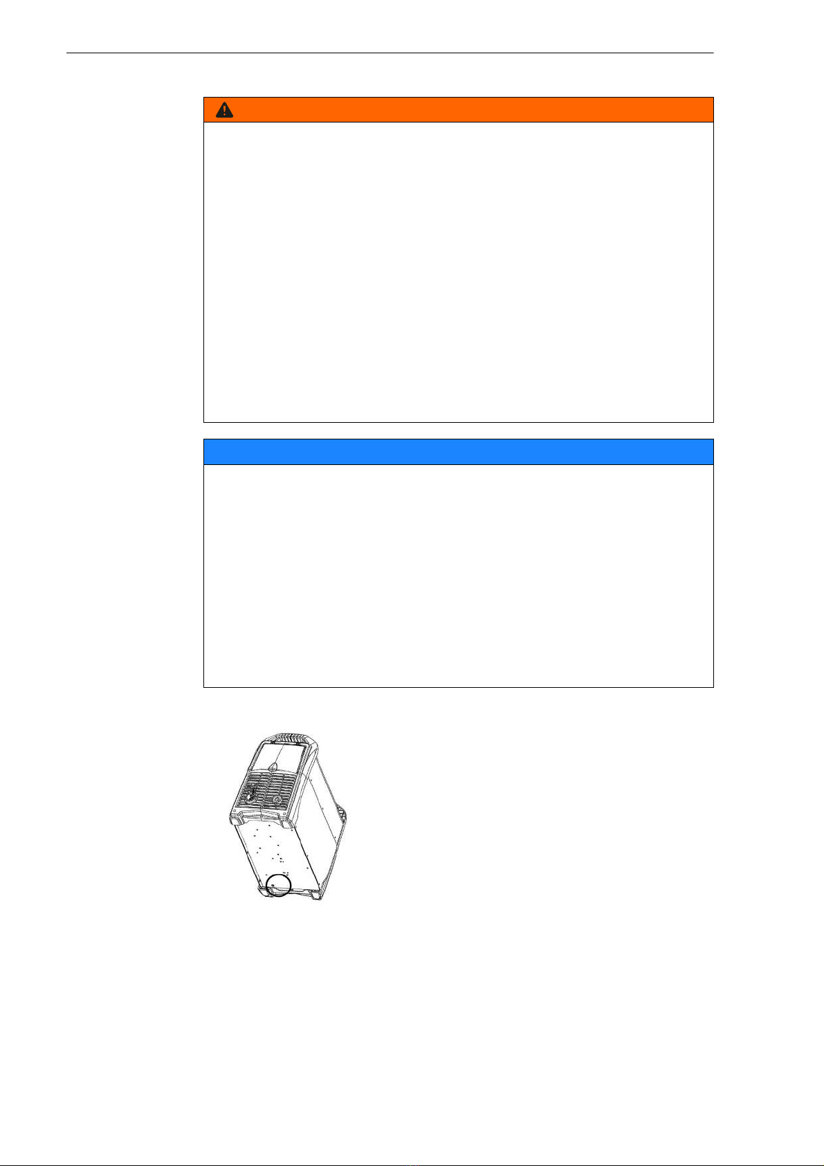
• When positioning the device, make
sure that the water separator's drain
opening is not covered.
EX-TRAFIRE®05HD 6 Commissioning
EN - 15
6 Commissioning
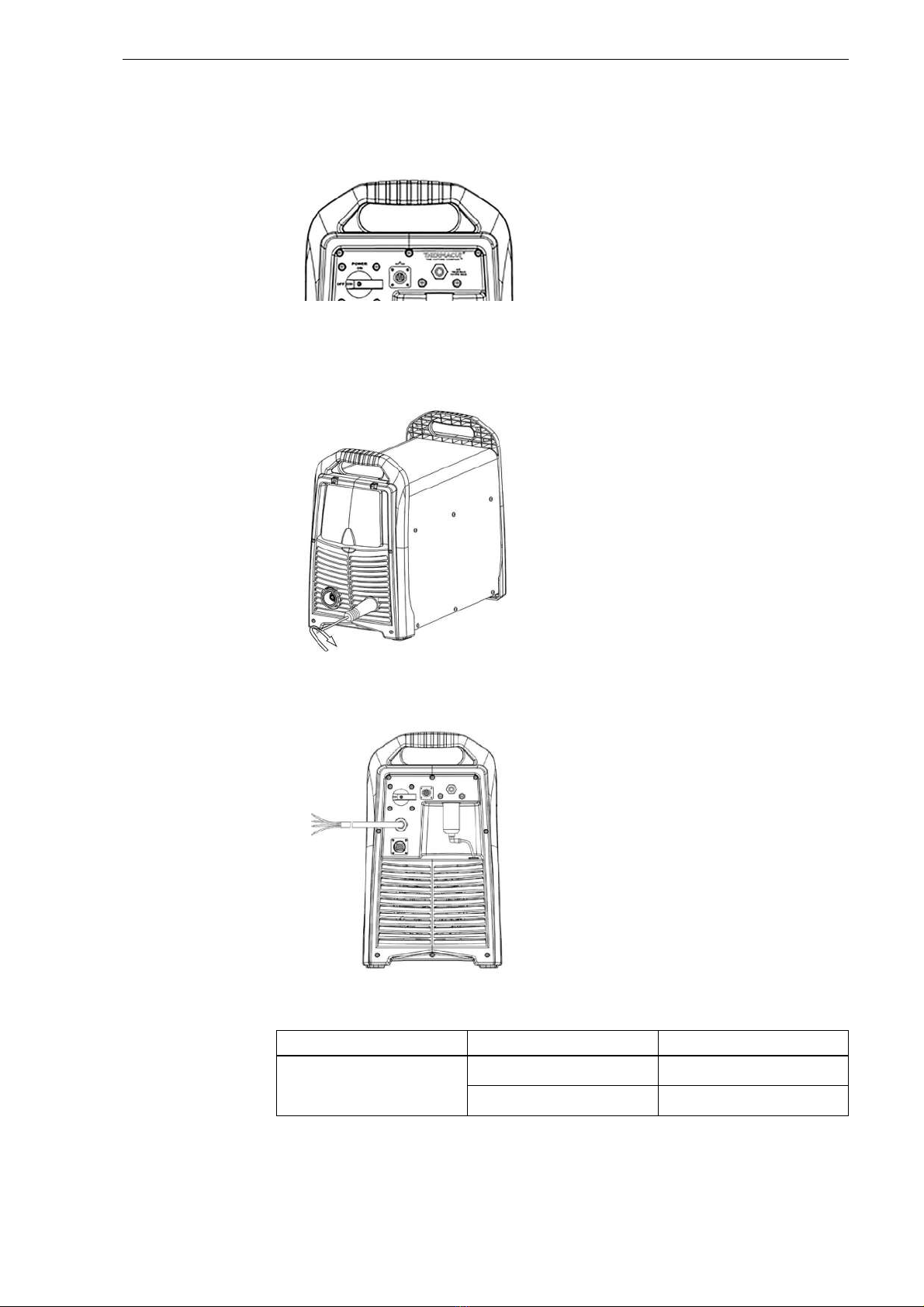
6.1 Connecting to the gas supply
6.2 Connecting the ork lead
6.3 Connecting the po er supply cable
• Connect the gas hose with an inside
diameter of at least 6 mm to the gas
connection of the device.
• Connect the work lead to the <Work
lead> connecting socket and secure
it by rotating clockwise.
• The power supply should be
connected by a qualified electrician.
L1 -> black (U)
L2 -> brown (V)
L3 -> gray (W)
Grounding -> green-yellow
Tab. 7 Recommended cable extensions
Input voltage Wire cross-sections Length
00 V AC/3 phases 6 mm2Up to 15 m
10 mm215– 5 m
Black
Green-yellow
Grey
Brown

EN - 16
6 Commissioning EX-TRAFIRE®05HD
6.4 Connecting the cutting torch
• Switch off the power supply.
6.5 Establishing the po er supply
• Note the safety instructions.
2.5 Safety instructions for the electrical power supply on page EN-8
1Insert the TCS Latch with Key
Assembly into the TCS socket.
• The TCS Latch with Key Assembly
must sit firmly in the TCS socket.
2Push the cutting torch into the TCS
and ensure the Latch with Key
Assembly locks in place.
WARNING
Electric shock due to improperly installed electrical power supply
If the electrical power supply and grounding are improperly installed,
fatal electric shocks may occur.
• If you want to operate the device in a very humid environment or on
conductive material, install a residual current circuit breaker in the
power supply.
• Use quick residual current circuit breakers.
• Protect the power supply line to the device with suitable fuses that
comply with regulations.
• Ground the device according to the applicable regulations.
• Do not ground the device together with other devices and machines.

EX-TRAFIRE®05HD 6 Commissioning
EN - 17
For the input voltage and the fuse protection, please refer to:
.2 Technical data on page EN-11
• If necessary, have a qualified electrician connect the input power cable
extension in accordance with local regulations.
• Ensure that the power supply is adequately protected by a safety switch.
• Insert the mains plug of the power cable into the corresponding socket.
Connection to a generator (optional)
• Set the generator to three-phase alternating current.
• Plug the mains plug into the socket.
• Set the motor rating as shown in the following table.
6.6 Connecting the CNC interface
The CNC interface is on the rear of the device. Control signals can be
transmitted via the CNC interface. The signal types can be found in the
table. The control elements are located on the control panel. The
connections are on the front and rear of the device.
The control elements are located on the control panel. The connections
are on the front and rear of the device. on page EN-10
WARNING
Risk of electric shock due to improperly installed and defective
cables
Damaged or improperly installed cables can lead to fatal electric shock.
• Check all live cables and connections for proper installation and
damage.
• Damaged, deformed or worn parts should only be replaced by a
qualified electrician.
WARNING
Risk of injury due to fire
Improper use or connection can result in fire. This may result in serious
burns.
• Ensure that the operating voltage specified on the identification plate
is suitable for the input voltage.
Tab. 8 Connection to a generator
Generator motor rating Output current (I2) Arc voltage
≥ 30 kW 105 A U2 = 200 V DC
WARNING
Electric shock due to live parts
Live parts are exposed when the housing is open. This can result in fatal
electric shocks.
• Set the <POWER> switch to <OFF> and disconnect the mains plug
before opening the housing.
EN - 18
6 Commissioning EX-TRAFIRE®05HD
6.6.1 Setting the DIP s itches
The DIP switches are preset to 50:1.
1The housing must be opened only by a qualified electrician.
2The DIP switches must be set only by a qualified electrician.
Fig. DIP switch settings on page EN-18
3The housing must be closed only by a qualified electrician.
4Have a safety inspection performed in accordance with DIN IEC 6097
Part : “Periodic inspection and testing” by Thermacut® or another
authorized specialist.
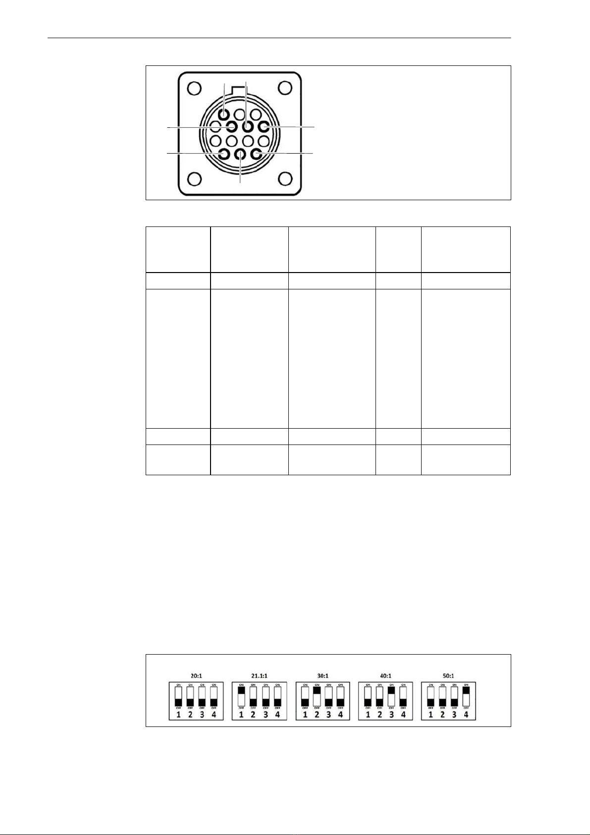
Fig. 3 Pin assignment for CNC interface
Tab. 9 Pin assignment
Signal START
Start plasma
cutting
Arc
Start feeding
PE Voltage divider
Type Input Output PE Output
Notice Open by
default.
Requires
potential-free
contact to
close.
Open by
default.
Potential-free
with max.
capacity of:
120 V AC/1 A
Reduced arc
signal:
20:1
21.1:1
30:1
0:1
50:1
(supplies max.
18 V)
PIN 3, 12, 1 13 6 (+), 5 (−)
Internal
cable color
White, white Yellow, yellow Green/
yellow
6 (red), 5 (black)
4
12
6
14
3 5
13
Fig. 4 DIP switch settings
EX-TRAFIRE®05HD 6 Commissioning
EN - 19
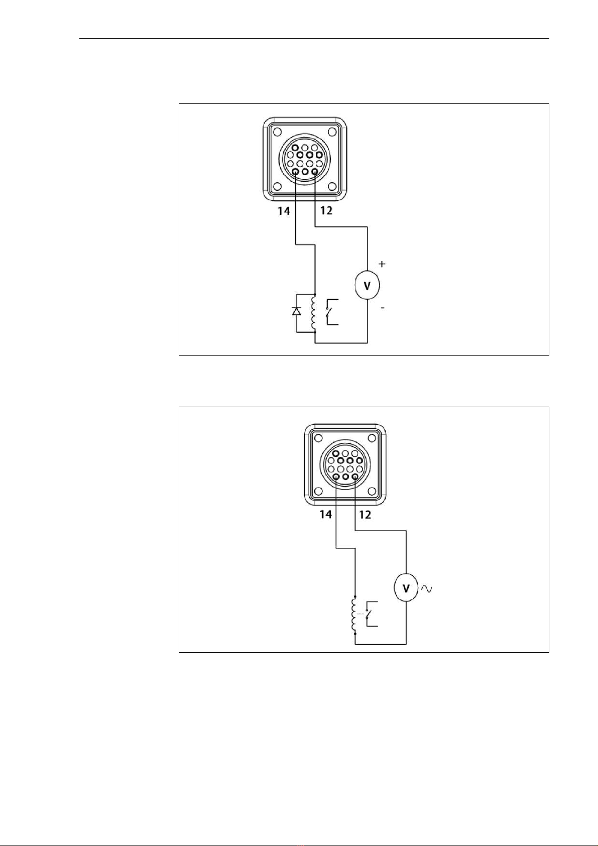
6.6.2 Enabling the external DC coil ith an external po er supply
• For 2 V DC, use a 1N 007 diode.
6.6.3 Enabling the external AC coil ith an external po er supply
Fig. 5 Enable the external DC coil with an external power supply.
2 V DC
Use diode
1N 007 if the
voltage is
2 V DC.
Fig. 6 Enable the external AC coil with an external power supply.
2 V AC
230 V AC

EN - 20
6 Commissioning EX-TRAFIRE®05HD
6.6.4 Enabling the industrially insulated module ith an
external po er supply
Industrial insulated user module with 2 V DC power supply.
6.6.5 Installing the cutting torch's gear rack
1Switch off the device.
2Remove the interface cover.
3Connect the interface cable with the
cutting power supply.
Insulated
module
Fig. 7 Cutting torch
AMounting sleeve with torch body
BReduction nut
CMounting tube
DStrain relief
ECable
1Disconnect the machine cutting torch
from the cutting power supply.
2Place on a flat surface.
3Unscrew the strain relief so that it can
move freely along the torch cable.
4Unscrew the mounting tube from the
reduction nut. Hold the reduction nut
and the mounting sleeve in order not
to damage the cables.
5Carefully hold the reduction nut and
mounting sleeve with the torch body
to the side.
6Push the gear rack into the groove of
the mounting tube.
A B C D E
Other manuals for EX-TRAFIRE 105HD
1
Table of contents
Other THERMACUT Power Supply manuals

Popular Power Supply manuals by other brands


RS PRO
RS PRO RS3000 Series user manual

Lucent Technologies
Lucent Technologies INDeX 20DS Turret user guide

Altronix
Altronix WayPoint30A Series installation guide

Pulsar
Pulsar AWZ 222 manual

Lutron Electronics
Lutron Electronics QSPS-P1-1-50 installation instructions

Toshiba
Toshiba W7 Series Brochure & specs